1 Introduction
Falling liquid films have been intensively studied for decades due to their relevance in energy and process engineering as well as in fundamental research. Known to provide high heat and mass transfer rates, they are found in a multitude of applications such as falling film evaporators, heat exchangers and gas absorption processes. Besides their relevance in industrial application, falling liquid films constitute a prominent example of a hydrodynamic instability and therefore are well studied in the framework of the investigation of complexity and transition to chaos (Alekseenko, Nakoryakov & Pokusaev Reference Alekseenko, Nakoryakov and Pokusaev1994; Chang & Demekhin Reference Chang and Demekhin2002; Kalliadasis et al. Reference Kalliadasis, Ruyer-Quil, Scheid and Velarde2012).
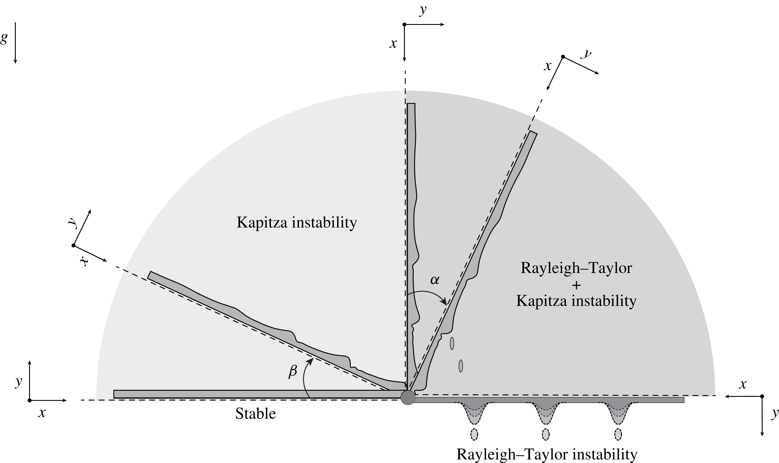
The transition to a chaotic film topology from a plain, laminar film flow undergoes multiple transitions leading to specific flow structures whose influence on the scalar transport properties of the film flow have been reported in several studies. This includes the onset of flow reversal in the capillary region (Dietze, Leefken & Kneer Reference Dietze, Leefken and Kneer2008; Malamataris & Balakotaiah Reference Malamataris and Balakotaiah2008), the onset of rolling waves (Brauner & Maron Reference Brauner and Maron1983; Dietze et al. Reference Dietze, Rohlfs, Nährich and Scheid2014; Rohlfs Reference Rohlfs2015) and critical film thinning due to Marangoni forces in the case of non-isothermal film flows (Lel et al. Reference Lel, Kellermann, Dietze, Kneer and Pavlenko2008; Chinnov & Abdurakipov Reference Chinnov and Abdurakipov2012; Rietz et al. Reference Rietz, Rohlfs, Kneer and Scheid2015). Besides the influence of imposed flow rates (or film thickness) and fluid properties on film evolution, a significant influence of wall inclination on the stability and evolution of falling films is intuitive as summarized in figure 1.
A film on top of a horizontal surface is inherently stable, all initial deviations of the film surface from a flat film decline with time (
 $\unicode[STIX]{x1D6FD}=0$
, figure 1). For inclination angles from the horizontal in the range of
 $0<\unicode[STIX]{x1D6FD}\leqslant \unicode[STIX]{x03C0}/2$
(see figure 1) the Kapitza instability, arising for a Reynolds number
 $Re>5/6\cot \unicode[STIX]{x1D6FD}$
(Benjamin Reference Benjamin1957; Yih Reference Yih1963), leads to a deformation of the film surface in the form of traveling waves, growing in amplitude until saturation eventually arises. This range of inclinations has been investigated in many research studies. A comprehensive and recent review is presented by Kalliadasis et al. (Reference Kalliadasis, Ruyer-Quil, Scheid and Velarde2012). For a flow on the underside of an inclined wall (
 $0<\unicode[STIX]{x1D6FC}<\unicode[STIX]{x03C0}/2$
; right part of figure 1) the situation is more diverse, grounded in the superposition of the Kapitza instability and the Rayleigh–Taylor instability (Taylor Reference Taylor1950; Sharp Reference Sharp1984), induced by the destabilizing effect of gravitational acceleration. In the limit of a film on the underside of a horizontal wall, the Kapitza instability vanishes and the film surface is solely deformed by the Rayleigh–Taylor instability. Interestingly, besides the importance of the film flow under an inclined wall (
 $0<\unicode[STIX]{x1D6FC}<\unicode[STIX]{x03C0}/2$
) regarding its occurrence in applications, efforts for increasing the theoretical understanding of the film evolution in this case have only recently been undertaken.
Abdelall et al. (Reference Abdelall, Abdel-Khalik, Sadowski, Shin and Yoda2006) have experimentally and numerically investigated the evolution of a liquid film on the underside of a horizontal and slightly inclined porous wall through which the working fluid was fed. Properties of detaching droplets were analysed, however, employing very small inclination angles from the horizontal, the transition from a hydrodynamic instability to the Rayleigh–Taylor instability was not in focus. Later, Lin, Kondic & Filippov (Reference Lin, Kondic and Filippov2012) have considered the destabilization of a film through Rayleigh–Taylor instability under an initially non-wetted plate. They found a significant influence of contact line instabilities on the film topology describing the development of rivulet structures and superimposed hydrodynamic waves. Recently, Rohlfs, Pischke & Scheid (Reference Rohlfs, Pischke and Scheid2017) have investigated the influence of wall inclination on the onset of rolling waves and flow reversal using a weighted integral boundary layer model (Ruyer-Quil & Manneville Reference Ruyer-Quil and Manneville2000) and direct numerical simulations putting in evidence an onset for dripping, even though only two-dimensional (2-D) waves were considered. Brun et al. (Reference Brun, Damiano, Rieu, Balestra and Gallaire2015) and Scheid, Kofman & Rohlfs (Reference Scheid, Kofman and Rohlfs2016) have characterized the transition from the vertical wall case (
 $\unicode[STIX]{x1D6FC}=0$
) to the Rayleigh–Taylor problem (
 $\unicode[STIX]{x1D6FC}=\unicode[STIX]{x03C0}/2$
) by introducing the concept of a transition from a convective to an absolute instability. A critical inclination angle
 $\unicode[STIX]{x1D6FC}$
was suggested for which initial disturbances are no longer convected with a film flow along the wall (convective instability), but grow locally in the laboratory frame of reference (absolute instability). Experimentally, Brun et al. (Reference Brun, Damiano, Rieu, Balestra and Gallaire2015) identified this transition in the form of droplet detachment from the bounding wall, realizing a constant film thickness as an initial stage. Theoretically, Scheid et al. (Reference Scheid, Kofman and Rohlfs2016) have shown that the transition becomes non-monotonic (varying with the imposed flow rate or film thickness) if inertia and extensional viscous effects, neglected in theoretical considerations of Brun et al. (Reference Brun, Damiano, Rieu, Balestra and Gallaire2015), are accounted for.
Stability phenomena involved in falling liquid films for various wall inclinations.

A film flow under an inclined wall may be regarded as part of a more general problem: a falling film under the influence of a destabilizing body force. Thereby, the connection to related problems involving film flow under curved or on rotating substrates becomes straightforward. Several studies have treated the problem of a falling film on the outer surface of a rotating cylinder, where centrifugal acceleration induces a destabilizing body force and Rayleigh–Taylor type instability. In an experimental study, Cheng & Cordero (Reference Cheng and Cordero1963) observed rivulet formation and droplet detachment, giving empirical correlations for the diameter of detaching droplets. Theoretical investigations into the stability of such flows are presented in the framework of the lubrication approximation by Dávalos-Orozco & Ruiz-Chavarría (Reference Dávalos-Orozco and Ruiz-Chavarría1993) and Chen, Chen & Yang (Reference Chen, Chen and Yang2004) showing the destabilizing effect of increasing rotational speed or decreasing the cylinder diameter. Regarding film flows under curved substrates, the recent studies of Trinh et al. (Reference Trinh, Kim, Hammoud, Howell, Chapman and Stone2014) and Balestra, Brun & Gallaire (Reference Balestra, Brun and Gallaire2016) should be mentioned, which consider the coating flow on the inside of a horizontal cylinder. Conditions are identified for which a draining flow along the curved cylinder wall suppresses droplet formation through Rayleigh–Taylor instability.
This study presents experimental data of the film evolution on the outside of a rotating cylinder of large radius. A constant flow rate condition, most common in application, is realized. At the same time, negligible curvature allows for comparability to the standard inclined wall problem. In this framework, several open questions regarding the film evolution are addressed. First, it remains unclear, whether the transition from a film dominated by Kapitza instability to a film dominated by Rayleigh–Taylor instability shows itself through a sharp regime transition, as suggested by linear stability analysis (Brun et al. Reference Brun, Damiano, Rieu, Balestra and Gallaire2015; Scheid et al. Reference Scheid, Kofman and Rohlfs2016) or a continuous evolution of the surface topology. Likewise, it has to be clarified, under which circumstances and through which mechanisms droplet detachment from the substrate might occur and to which extent linear arguments (Brun et al. Reference Brun, Damiano, Rieu, Balestra and Gallaire2015; Scheid et al. Reference Scheid, Kofman and Rohlfs2016) allow for a prediction of this behaviour.
The remainder of this paper is structured as follows. In § 2 the experimental set-up and experimental conditions are introduced. Subsequently, experimental results are presented in § 3. At first, a qualitative description of the film evolution is provided, identifying different flow regimes (§ 3.1). Thereafter, properties of distinct flow features are quantified and compared to predictions from linear stability analysis (§§ 3.2 and 3.3). Conclusions are summarized in § 4.
2 Experimental set-up
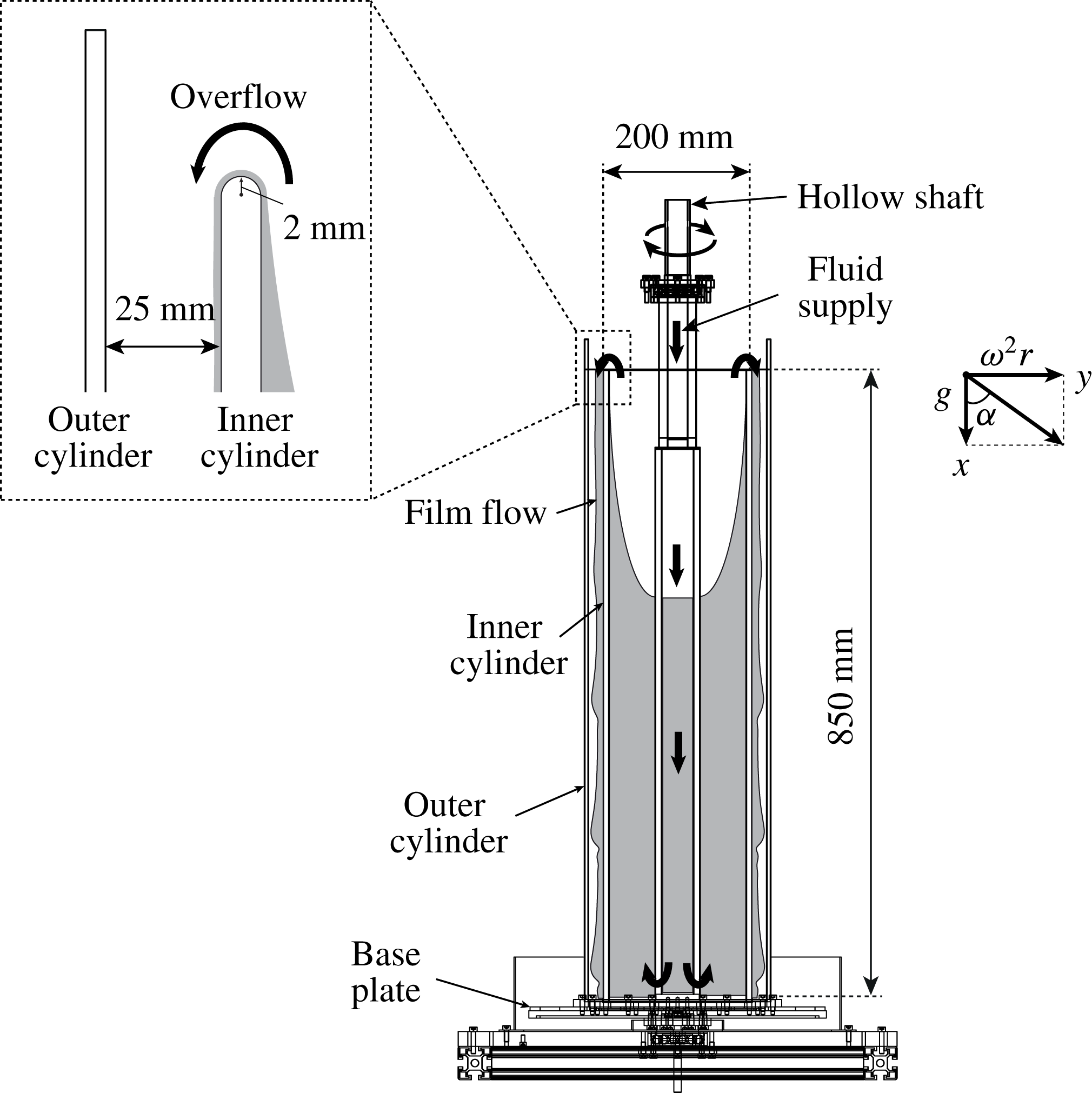
The experimental set-up designed and constructed for the present study is illustrated in figure 2. For better visibility of the system functionality, a sectional view through the symmetry axis of the set-up reveals the composition of the system and the fluid path (black arrows). A hollow shaft connected to a base plate is rotatably mounted between an upper and a lower bearing, which are in turn fixed through steel plates connected to a solid frame (not shown). Two additional concentric cylinders (inner and outer cylinder) are mounted on the same base plate, so that, moving in radial direction from the symmetry axis, three gaps are formed. The working fluid is supplied from the top through the hollow shaft. A connection to the space between shaft and inner cylinder at the bottom of the system allows the fluid to rise and finally form a film on the outer side of the inner cylinder. The overflow condition is detailed on the left of figure 2. The outer (transparent) cylinder is installed to reduce shear at the film surface by inducing a co-rotating air flow between the cylinders. Additionally, it acts as a protective shield against potentially detaching fluid. Finally, the working fluid leaves the system over radial channels in the base plate into a reservoir and is subsequently transported back to the fluid inlet through a centrifugal pump, completing the fluid loop.
Sectional view of the experimental set-up including fluid path (black arrows). A liquid film is imposed on the outside of the inner cylinder through an overflow, illustrated in the top-left insert. The outer co-rotating, transparent cylinder minimizes shear related influences and additionally acts as a protective shield against detaching droplets.

The system is designed as an analogy to the case of a film flow under an inclined wall. For the inclined wall case, the specific body force acting on the fluid in a direction parallel or perpendicular to the flow is coupled (cannot be changed independently) and given by the respective components of the gravitational acceleration. In that sense, the component perpendicular to the wall is zero for a vertical wall and reaches its maximum for an inclination of
 $90^{\circ }$
from the vertical. For the case considered here – a vertically oriented, rotating cylinder –, the two components are de-coupled, with a constant acceleration of the fluid parallel to the wall (gravitational acceleration
 $g$
) and a variable acceleration perpendicular to the wall in form of the centrifugal acceleration
 $\unicode[STIX]{x1D714}^{2}r$
, with
 $\unicode[STIX]{x1D714}$
the angular velocity of the cylinder and
 $r$
the cylinder radius. Analogy between the rotating system (‘rotation’) and the inclined wall (‘wall’) case is given through the ratio between the present accelerations acting on the fluid and a resulting effective inclination angle
 $\unicode[STIX]{x1D6FC}$
by
 $$\begin{eqnarray}\text{tan}(\unicode[STIX]{x1D6FC})=\frac{g_{y,wall}}{g_{x,wall}}=\frac{g_{y,rotation}}{g_{x,rotation}}=G,\end{eqnarray}$$
where
 $$\begin{eqnarray}\left.\begin{array}{@{}c@{}}\displaystyle g_{x,wall}=g\,\text{cos}(\unicode[STIX]{x1D6FC}),\quad g_{y,wall}=g\,\text{sin}(\unicode[STIX]{x1D6FC}),\\ \displaystyle g_{x,rotation}=g,\quad g_{y,rotation}=g\,\text{tan}(\unicode[STIX]{x1D6FC})=\unicode[STIX]{x1D714}^{2}r,\end{array}\right\}\end{eqnarray}$$
with
 $x$
pointing in the flow direction along the wall and
 $y$
pointing in the cross-stream direction, perpendicular to the wall. In the rotating system,
 $G$
is the quotient of centrifugal acceleration and gravitational acceleration. The experimental range for the value of
 $G$
is limited by the employed controllable electric motor, enabling the setting of variable rotational speeds of the base plate including mounted parts up to a maximal rotation frequency of approximately 500 rpm, which corresponds to
 $G=27.95$
for
 $r=10~\text{cm}$
.
The rotating system has several advantages over an inclined wall. First, the wall (in form of a cylinder) is a closed surface, eliminating edge effects from confining spanwise walls (Vlachogiannis et al.
Reference Vlachogiannis, Samandas, Leontidis and Bontozoglou2010). An example for the use of a closed surface can be found in the experimental work of Dietze, Al-Sibai & Kneer (Reference Dietze, Al-Sibai and Kneer2009), who investigated a film flow on the inside of a vertical tube. Furthermore, de-coupling the body force ratio enables an experimentally comfortable variation of the effective inclination
 $\unicode[STIX]{x1D6FC}$
through adjustment of the rotational speed. Nevertheless, a couple of differences to the inclined wall case are introduced through the change of system, which were considered in the design process of the set-up and are described in the following.
To minimize the effect of the curved surface on the stability and evolution of the film, a large diameter of the cylinder is required comprising the bounding wall for the film flow. The ratio of the characteristic dimensions for the film and the cylinder can be expressed as the quotient of the Nusselt flat film thickness
 $\bar{h}_{N}=l_{\unicode[STIX]{x1D708}}(3Re)^{1/3}$
with
 $l_{\unicode[STIX]{x1D708}}=\sqrt[3]{\unicode[STIX]{x1D708}^{2}/g}$
and the radius of the cylinder
 $r$
.
 $Re$
is the film Reynolds number (defined in Appendix A) and
 $\unicode[STIX]{x1D708}$
is the kinematic viscosity of the fluid. Under this premise, the maximal imposed flow rate in the conducted experiments, corresponding to
 $Re=1.6$
, gives a ratio of
 $\bar{h}_{N}/r=0.0014~\text{m}/0.1~\text{m}=0.014$
. The influence of curvature on the stability of a condensate film on the outer surface of a rotating cylinder has been investigated quite recently by Chen et al. (Reference Chen, Chen and Yang2004). Introducing a non-dimensional radius
 $R=r/\bar{h}_{N}$
, a negligible influence of the curvature on the stability was found for
 $R\gg 10$
, which is a condition met in this study. The same argument holds for the influence of the radius dependency of the centrifugal acceleration. The difference in acceleration across the film compared to the mean centrifugal acceleration acting on the film leads to the same expression (
 $\unicode[STIX]{x1D714}^{2}\bar{h}_{N}/\unicode[STIX]{x1D714}^{2}r=0.0014~\text{m}/0.1~\text{m}=0.014$
) and is hence marginal as well.
A last factor to be considered is the influence of rotational instabilities on the film evolution, which might be induced due to variations in angular velocity across the film. In this context, several measures have been taken in order to minimize the significance of any rotational instability and retain the comparability to a film flow under an inclined wall. First, shear at the liquid–gas interface is minimized through the outermost transparent cylinder, which induces a co-rotating air flow. Taking into account that the film is very thin, no significant variations in angular velocity should be present sufficiently downstream the fluid inlet. In fact, no shear related effects from the gas phase have been observed in the experiments. At the same time, small variations in angular velocity are expected right at the fluid inlet. However, due to the co-rotating fluid reservoir (see figure 2) fluid accelerates according to an only slight change in radius of
 $\unicode[STIX]{x0394}r=4~\text{mm}$
. No visible deflection of the film has been observed, with the exception of detaching droplets, showing a curved trajectory (see figure 4). Correspondingly, the significance of any rotational instability on film evolution is assumed to be negligible. This assumption is confirmed by experimental data presented in § 3.
The experimental conditions, including control parameters, fluid properties and dimensionless numbers, are summarized in appendix A.
3 Results
To provide a comprehensive analysis of the evolution of the film flow for varying Reynolds numbers and increasing rotational speed, the results section is split in three parts. First, a qualitative and visual description of the film evolution is given, identifying regime transitions (§ 3.1). Thereafter, a linear stability analysis of the problem in question is performed (§ 3.2) allowing for a rationalization of experimentally obtained spatial and temporal properties of distinct features of the film flow (§ 3.3).
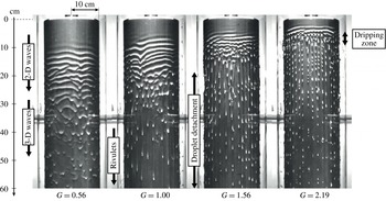
Images of the film on the rotating cylinder, showing the evolution of the film’s surface topology for increasing
 $G$
(0.56, 1.00, 1.56, 2.19),
 $Re=1.05$
and
 $Ka=5.1$
(Kapitza number, see definition in appendix A). The first 60 cm of the test section, starting from the overflow, are visible. Observed and labelled flow regimes include 2-D (ring) waves, 3-D waves, rivulet structures and a distinct dripping zone.

3.1 Evolution of the film topology: qualitative description
The following qualitative description of the film evolution for increasing rotational speed of the cylinder is carried out in the light of a transition from a pure Kapitza instability dictating the film development (in the limit
 $G\rightarrow 0$
) to a pure Rayleigh–Taylor instability dictating the film development (in the limit
 $G\rightarrow \infty$
). Within this framework, increasing the parameter
 $G$
implies increasing the relative significance of the Rayleigh–Taylor mechanism on the evolution of the film. Note that the assignment of distinct flow features to the previously mentioned instability mechanisms is at first intuitive and based on observation. A quantification of features of the film flow and thus a rationalization of the performed analysis follows in § 3.3.
Images of the film flow on the rotating cylinder for increasing values of
 $G$
are displayed in figure 3. The images are single frames extracted from high speed recordings of the rotating cylinder with a recording frequency of 500 Hz and show the top 60 cm of the experimental section, starting from the fluid inlet. Note, that the evolution is depicted for a single Reynolds number (
 $Re=1.05$
). The observed regime transitions are similar for different values of
 $Re$
, only differing in their spatial and temporal occurrences. Therefore, the pictures are representative for the regime changes observed within all conducted experiments.
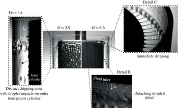
Evolution of the film’s surface topology for increasing
 $G$
(3.9, 6.6) (
 $Re=1.05=\text{const.}$
). The emergence of a distinct dripping zone is detailed for
 $G=3.9$
and visible as an increased amount of droplet impacts on the outer transparent cylinder. The onset of a regime of immediate dripping, where fluid detaches at the inlet in the form of equally spaced filaments, is detailed for
 $G=6.6$
.

For low values of
 $G$
(
 $G=0.56$
), the observed development of the film topology is similar to the development known from films on top of inclined or vertical walls (Alekseenko et al.
Reference Alekseenko, Nakoryakov and Pokusaev1994). Starting with a seemingly plane film, long wave disturbances develop in the form of 2-D ring waves, which subsequently destabilize into 3-D waves due to a secondary instability of the wave front. This latter has its origin in the local acceleration of the free surface and corresponds to the inertial mode identified by Kofman, Mergui & Ruyer-Quil (Reference Kofman, Mergui and Ruyer-Quil2014). The flow regime is clearly driven by a dominating Kapitza instability. Note that a connection between developing 2-D ring waves and the Rayleigh–Plateau mechanism (Duprat et al.
Reference Duprat, Ruyer-Quil, Kalliadasis and Giorgiutti-Dauphiné2007) is excluded due to the large cylinder radius. The most amplified wavelength of the Rayleigh–Plateau instability is
 $\unicode[STIX]{x1D706}\approx 90~\text{cm}=9.02r$
, which exceeds the streamwise extension of the set-up. For these reasons and due to negligible curvature, the 2-D axisymmetric ring waves will be referred to as 2-D waves in the remainder of the paper. For increased values of
 $G$
(
 $G=1$
) regularly spaced rivulets with droplets riding on top of them emerge from the 3-D wave structures within the length of the experimental set-up. For larger
 $G$
(
 $G=1.56$
), isolated droplet detachment from the rivulets is observed. Additionally, the streamwise expansion of 2-D and 3-D waves is compressed, placing the onset of rivulet structures closer to the fluid inlet. For
 $G=2.19$
, contrarily to the isolated dripping events, a stable dripping zone develops with droplet detachment occurring at a specific distance
 $L_{d}$
from the inlet. Due to the loss of fluid, a low Reynolds number flow is formed beneath the dripping zone dominated by rivulet structures with isolated dripping events occurring. Furthermore, 3-D wave structures are suppressed within the whole test section and developing 2-D waves directly destabilize into rivulets and detaching droplets. This hints at the increasing influence of the Rayleigh–Taylor instability when increasing the centrifugal force.
The further evolution of the film topology for increasing
 $G$
is displayed in figure 4. As
 $G$
is increased after the emergence of a dripping zone, the streamwise expansion of 2-D wave structures decreases, while at the same time the beginning of the dripping zone moves closer to the inlet, decreasing the corresponding inception length
 $L_{d}$
(
 $G=3.9$
, figure 4 left). Note that single droplet detachments still occur downstream the dripping zone. However, the majority of drops detach in the described localized region, clearly visible through a large amount of droplet impacts on the outer transparent cylinder (figure 4: detail A).
Finally, for
 $G=6.6$
, 2-D waves are no longer observed and the fluid detaches at a small distance from the fluid inlet in the form of equally spaced filaments (figure 4: detail B), observed as liquid bridges (figure 4: detail C) between inner and outer cylinder. This type of flow is known from spinning disc atomizers and has been experimentally observed in previous studies (Fraser, Dombrowski & Routley Reference Fraser, Dombrowski and Routley1963; Eisenklam Reference Eisenklam1964; Langley, Maynes & Truscott Reference Langley, Maynes and Truscott2015), where the equally spaced detachment was associated with a Rayleigh–Taylor type instability. In the present experiment, immediate fluid detachment at the inlet concludes the development from a flow dominated by Kapitza instability to a flow dominated by Rayleigh–Taylor instability. Naturally, a further disintegration of the filaments into single drops would be expected due to the Rayleigh–Plateau mechanism. This break-up is, however, not occurring due to the small distance between the inner and outer cylinder.
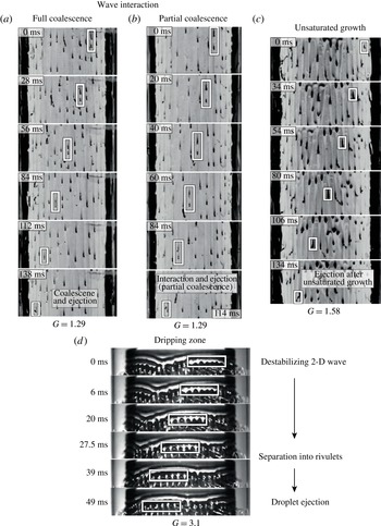
Dripping mechanisms for different values of
 $G$
: illustrations show (a) coalescence, (b) interaction with partial coalescence and (c) unsaturated growth of solitary waves on rivulets leading to localized dripping events. Illustration (d) displays immediate dripping after rivulet formation, leading to the formation of a distinct dripping zone.

The illustrated evolution of the film topology reveals that dripping is based on different mechanisms, depending on the value of
 $G$
. In all cases, however, dripping is observed as a strongly nonlinear phenomenon emerging from secondary instabilities of the wave pattern. The different mechanisms identified to lead to droplet detachment are summarized in figure 5. Thereby, a clear distinction between the regime of localized single dripping events along the whole streamwise extent of the set-up and the emergence of a local dripping zone is provided. Cases (a), (b) and (c) of figure 5 illustrate the different mechanisms observed outside of a distinct dripping zone. These are dripping after coalescence of waves on rivulets (a), dripping due to the interaction of waves of differing velocity on a single rivulet with partial coalescence (b) and the unsaturated growth of solitary waves on rivulets (c). Case (d) illustrates the mechanism leading to the formation of a distinct dripping zone. In each series of pictures, the corresponding event is marked by a dashed rectangle and tracked over consecutive frames. Note, dripping is only observed in association with the emergence of rivulet structures and correspondingly no dripping has been detected within the regime of 3-D waves. Hence, the concentration of liquid in rivulets is found to occur prior to any droplet detachment. The scenario is as follows: rivulets always occur first; subsequently, the increased local Reynolds number in a rivulet reinforces the growth of large amplitude riding waves, which in turn reinforce the Rayleigh–Taylor mechanism and eventually lead to dripping. Accordingly, preventing the formation of rivulets, provided it may be practically realized, might be a way to delay dripping.
Cases (a) and (b) are characterized by an interaction of multiple initially subcritical waves on rivulets. Both mechanisms rely on differences in wave celerity (Indeikina, Veretennikov & Chang Reference Indeikina, Veretennikov and Chang1997). In this context, dripping is either observed immediately after the coalescence of consecutive waves (a) or due to interactions of consecutive waves with partial coalescence (b). A clarification of the exact mechanisms which lead to a destabilization of the flow in case of wave interaction need further investigations that are beyond the scope of the present study. The nature of dripping events based on wave interaction suggests that dripping can occur at long distances from the fluid inlet even for marginal inclination angles or corresponding values of
 $G$
. In the case of unsaturated growth (c), single waves detach from the rivulets beyond a certain evolution length. The reason why this situation does not lead to a local dripping zone is supposed to lie in the preceding regime of 3-D waves, which leads to slight deviations in initial conditions of emerging rivulets.
Regarding the emergence of a local dripping zone (case d), ejection of droplets directly follows the destabilization of 2-D wavefronts into separate rivulets. Note, the formation of rivulets takes place in a time span of only approximately 30 ms. After separation, droplet ejection is observed within another 20 ms in the present case. In this context, a distinct zone of dripping forms due to several reasons. First, destabilization of 2-D wavefronts into rivulets occurs at an approximately fixed streamwise location. An extended regime of 3-D waves is thus suppressed and similar initial conditions of emerging rivulets are present. Second, the entire fluid mass contained in the former wavefront is now accumulated in waves on emerging rivulets. A super-critical state is immediately reached, leading to dripping.
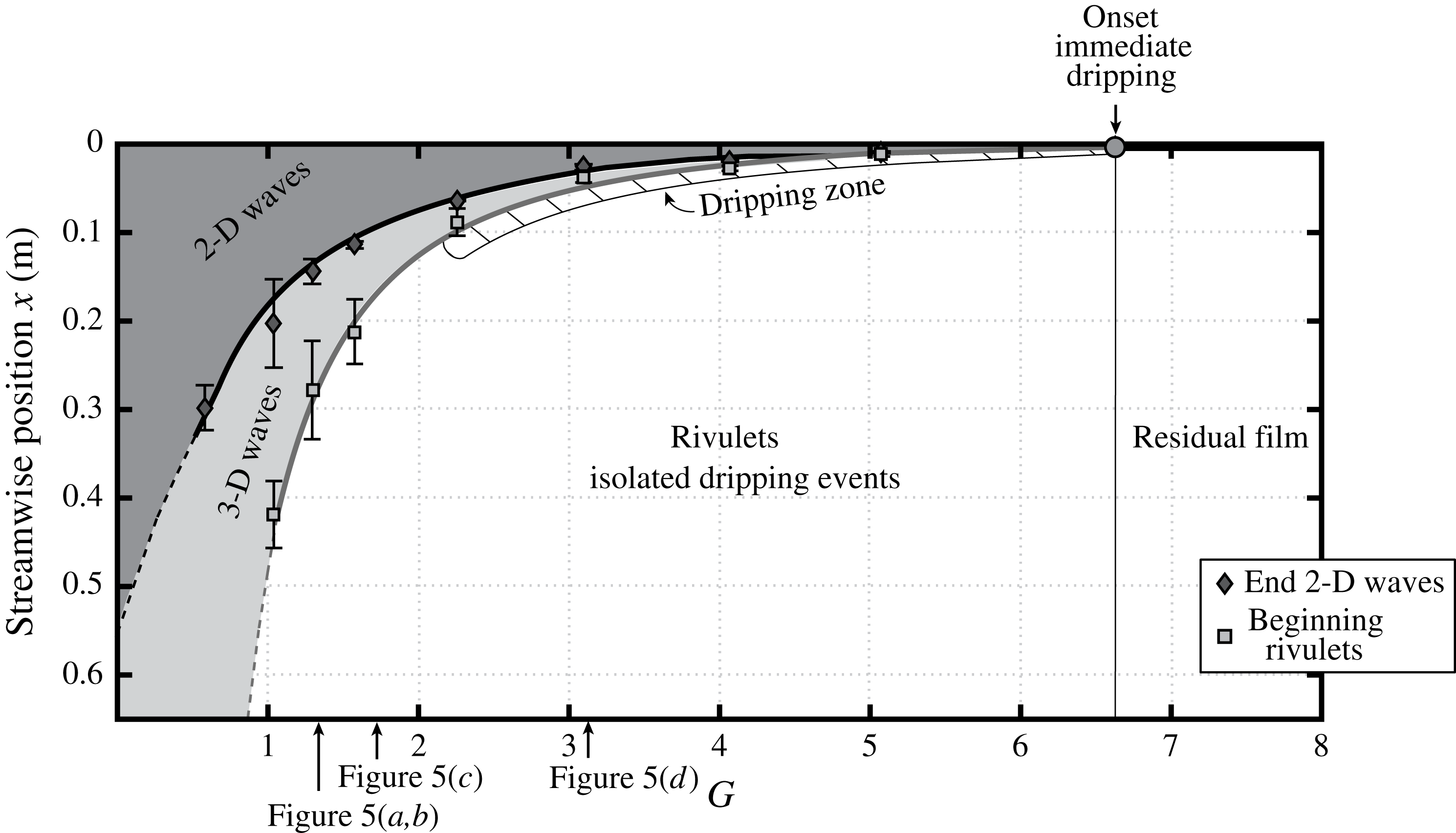
Summary of observed flow regimes including approximate locations of regime changes (2-D waves
 $\rightarrow$
3-D waves
 $\rightarrow$
rivulets) for
 $Re=1.05$
. The formation of a dripping zone and the onset of immediate dripping are indicated.

Previously described regime transitions for
 $Re=1.05$
are summarized in figure 6. In numerical studies regarding the interaction of hydrodynamic and thermocapillary instabilities in falling films, Scheid et al. (Reference Scheid, Kalliadasis, Ruyer-Quil and Colinet2008a
,Reference Scheid, Kalliadasis, Ruyer-Quil and Colinet
b
) employed the change of surface deformation energies in spanwise and streamwise direction as a criterion for the localization of film regime changes. This procedure, however, requires high quality quantitative data of the film surface, which were not attained in the present experiments. Therefore, spatial properties of the film evolution were visually extracted from high speed recordings on the basis of a large number of frames (500 images). Accordingly, displayed boundaries do not represent sharp transitions, but rather an approximate location of the regime transition. In this context, the transitions from a regime dominated by 2-D waves to a regime dominated by 3-D waves and finally to a regime dominated by rivulet structures are tracked, providing a comprehensive illustration of the film evolution. Additionally, the transitions from isolated dripping events to a distinct dripping zone and finally immediate dripping are indicated.
The influence of an increasing body force on the evolution of the film topology most dominantly manifests itself in the emergence of rivulet structures and a decreasing associated wave and inception lengths (figures 3 and 6). This development is accompanied with a decreasing wavelength of 2-D waves (figure 3), which, for all values of
 $G$
, precede the rivulet regime. Because 2-D wave structures with a distinct wavelength also develop in the absence of a destabilizing body force (Alekseenko et al.
Reference Alekseenko, Nakoryakov and Pokusaev1994; Chang & Demekhin Reference Chang and Demekhin2002; Kalliadasis et al.
Reference Kalliadasis, Ruyer-Quil, Scheid and Velarde2012), the evolution of their most dominant wavelength can additionally be used to analyse the transition from a film flow dominated by the Kapitza instability to a system dominated by the Rayleigh–Taylor instability. Provided 2-D waves as well as rivulets result from primary instabilities of the film flow, a comparison of experimentally attained spatial properties of 2-D waves and emerging rivulets to properties predicted by linear stability analysis is supposed to reveal the nature of the transition. Because droplet detachment is intimately related to the existence of rivulets, a linear stability analysis also allows for an evaluation of the predictability of nonlinear dripping.
3.2 Linear stability analysis
The linear stability analysis of the film flow is based on the dispersion relation of the full second-order integral boundary layer (WIBL) model obtained by Ruyer-Quil & Manneville (Reference Ruyer-Quil and Manneville2000), which has been shown to capture film properties in the linear stage in excellent agreement (Ruyer-Quil & Manneville Reference Ruyer-Quil and Manneville2002) with exact properties obtained through an Orr–Sommerfeld analysis. The derivation of the dispersion relation from the full model is briefly outlined in appendix B. The model has been widely used in recent literature (Scheid et al. Reference Scheid, Kalliadasis, Ruyer-Quil and Colinet2008a ; Rohlfs & Scheid Reference Rohlfs and Scheid2015; Scheid et al. Reference Scheid, Kofman and Rohlfs2016) and assessed by comparison to direct numerical simulation (Chakraborty et al. Reference Chakraborty, Nguyen, Ruyer-Quil and Bontozoglou2014; Dietze et al. Reference Dietze, Rohlfs, Nährich and Scheid2014). Note that the model assumes the film flow on a substrate with zero curvature. Comparison of experimental results to model predictions is justified by the negligible curvature of the cylinder. The dispersion relation in Nusselt scaling (Kalliadasis et al. Reference Kalliadasis, Ruyer-Quil, Scheid and Velarde2012) reads:
 $$\begin{eqnarray}\left.\begin{array}{@{}rcl@{}}\displaystyle 0\ & =\ & \displaystyle A+Bk+Ck^{2}+Dk^{3}+Ek^{4}+Fk^{5}+Gk^{6},\\ \displaystyle A\ & =\ & \displaystyle 3\text{i}\unicode[STIX]{x1D6FE}+{\textstyle \frac{54}{13}}Re\unicode[STIX]{x1D6FE}^{2}-{\textstyle \frac{90}{143}}\text{i}Re^{2}\unicode[STIX]{x1D6FE}^{3}-{\textstyle \frac{12}{715}}Re^{3}\unicode[STIX]{x1D6FE}^{4},\\ \displaystyle B\ & =\ & \displaystyle -3\text{i}-{\textstyle \frac{522}{143}}Re\unicode[STIX]{x1D6FE}+{\textstyle \frac{98}{143}}\text{i}Re^{2}\unicode[STIX]{x1D6FE}^{2}+{\textstyle \frac{108}{5005}}Re^{3}\unicode[STIX]{x1D6FE}^{3},\\ \displaystyle C\ & =\ & \displaystyle -Ct+{\textstyle \frac{498}{715}}Re+\unicode[STIX]{x1D6FE}\left({\textstyle \frac{27}{5}}\text{i}+{\textstyle \frac{12}{65}}\text{i}Ct\,Re-{\textstyle \frac{2936}{13013}}\text{i}Re^{2}\right)\qquad \\ \displaystyle \ & \ & +\displaystyle \,\unicode[STIX]{x1D6FE}^{2}\left({\textstyle \frac{3231}{3640}}Re+{\textstyle \frac{27}{5005}}Ct\,Re^{2}-{\textstyle \frac{612}{65065}}Re^{3}\right)-{\textstyle \frac{2027}{80080}}\text{i}Re^{2}\unicode[STIX]{x1D6FE}^{3},\\ \displaystyle D\ & =\ & \displaystyle -{\textstyle \frac{12}{5}}\text{i}-{\textstyle \frac{304}{5005}}\text{i}Ct\,Re+{\textstyle \frac{1368}{65065}}\text{i}Re^{2}\\ \displaystyle \ & \ & \displaystyle +\,\unicode[STIX]{x1D6FE}\left(-{\textstyle \frac{2441}{4004}}Re-{\textstyle \frac{16}{5005}}Ct\,Re^{2}+{\textstyle \frac{1104}{715715}}Re^{3}\right)+\,{\textstyle \frac{3439}{145600}}\text{i}Re^{2}\unicode[STIX]{x1D6FE}^{2},\\ \displaystyle E\ & =\ & \displaystyle {\textstyle \frac{30993}{320320}}Re+{\textstyle \frac{148}{325325}}Ct\,Re^{2}-{\textstyle \frac{48}{715715}}Re^{3}\\ \displaystyle \ & \ & \displaystyle -\,We+\unicode[STIX]{x1D6FE}\left(-{\textstyle \frac{4591}{650650}}\text{i}Re^{2}+{\textstyle \frac{12}{65}}\text{i}We\,Re\right)+{\textstyle \frac{27}{5005}}We\,Re^{2}\unicode[STIX]{x1D6FE}^{2},\\ \displaystyle F\ & =\ & \displaystyle {\textstyle \frac{1773}{2602600}}\text{i}Re^{2}-{\textstyle \frac{304}{5005}}\text{i}We\,Re-{\textstyle \frac{16}{5005}}We\,Re^{2}\unicode[STIX]{x1D6FE},\\ \displaystyle G\ & =\ & \displaystyle {\textstyle \frac{148}{325325}}We\,Re^{2}.\end{array}\!\!\!\!\right\}\end{eqnarray}$$
The dimensionless parameters
 $$\begin{eqnarray}\left.\begin{array}{@{}c@{}}\displaystyle Re=\frac{g_{x,rotation}\bar{h}_{N}^{3}}{3\unicode[STIX]{x1D708}^{2}},\quad We=\frac{\unicode[STIX]{x1D70E}}{\unicode[STIX]{x1D70C}g_{x,rotation}\bar{h}_{N}^{2}},\quad Ct=-\frac{g_{y,rotation}}{g_{x,rotation}}=-G,\\ \displaystyle k\quad \text{and}\quad \unicode[STIX]{x1D6FE}\end{array}\right\}\end{eqnarray}$$
are the Reynolds, Weber and inclination number, dimensionless wavenumber and dimensionless angular frequency. For a comparison to experimental data, dimensional wavenumber and angular frequency can be obtained through the transformations
 $k\rightarrow k\bar{h}_{N}$
and
 $\unicode[STIX]{x1D6FE}\rightarrow \unicode[STIX]{x1D6FE}\unicode[STIX]{x1D708}g_{x,rotation}^{-1}\bar{h}_{N}^{-1}$
. In a temporal analysis, the growth rate of perturbations with a real wavenumber
 $k$
can be obtained by assuming a complex angular frequency
 $\unicode[STIX]{x1D6FE}=\unicode[STIX]{x1D6FE}_{r}+\text{i}\unicode[STIX]{x1D6FE}_{i}$
and solving equation (3.1), which is a polynomial in
 $\unicode[STIX]{x1D6FE}$
of degree four, for the root with largest imaginary part. From this point, the determination of the most amplified wavelength is straightforward.
Regarding the transformation from a dominating influence of the Kapitza instability to a dominating influence of the Rayleigh–Taylor instability on the film evolution, the respective limiting cases of equation (3.1) are of interest. A pure Kapitza instability is represented for a vanishing destabilizing body force, i.e.
 $Ct=G=0$
. A pure Rayleigh–Taylor instability is characterized by a vanishing film flow along the wall, i.e.
 $Re=0$
. In fact, the dispersion relation of the Rayleigh–Taylor type instability for a thin wall bound film (Babchin et al.
Reference Babchin, Frenkel, Levich and Sivashinsky1983; Fermigier et al.
Reference Fermigier, Limat, Wesfreid, Boudinet and Quillet1992) can be retrieved from equation (3.1) and provides analytical expressions for the most amplified wavelength and an associated growth rate. Assuming
 $Re=0$
in (3.1) leads to the simplified dispersion relation
 $$\begin{eqnarray}3\text{i}\unicode[STIX]{x1D6FE}-3\text{i}k+\left({\textstyle \frac{27}{5}}\text{i}-Ct\right)k^{2}-{\textstyle \frac{12}{5}}\text{i}k^{3}-We\,k^{4}=0,\end{eqnarray}$$
in which the terms
 ${\textstyle \frac{27}{5}}\text{i}k^{2}$
and
 $-{\textstyle \frac{12}{5}}\text{i}k^{3}$
account for viscous dispersive effects (Kalliadasis et al.
Reference Kalliadasis, Ruyer-Quil, Scheid and Velarde2012). Neglecting those terms, equation (3.3) reduces to the dispersion relation of the Rayleigh–Taylor type instability for a thin wall bound film (Babchin et al.
Reference Babchin, Frenkel, Levich and Sivashinsky1983; Fermigier et al.
Reference Fermigier, Limat, Wesfreid, Boudinet and Quillet1992)
 $$\begin{eqnarray}\unicode[STIX]{x1D6FE}=-{\textstyle \frac{1}{3}}\text{i}(We\,k^{4}+Ct\,k^{2})+k.\end{eqnarray}$$
The dimensional expression for the imaginary part of the angular frequency reads
 $$\begin{eqnarray}\unicode[STIX]{x1D6FE}_{i}=\frac{\bar{h}_{N}^{3}}{3\unicode[STIX]{x1D702}}\left[\unicode[STIX]{x1D70C}g_{y}\left(\frac{2\unicode[STIX]{x03C0}}{\unicode[STIX]{x1D706}}\right)^{2}-\unicode[STIX]{x1D70E}\left(\frac{2\unicode[STIX]{x03C0}}{\unicode[STIX]{x1D706}}\right)^{4}\right],\end{eqnarray}$$
with
 $\bar{h}_{N}$
the Nusselt flat film thickness,
 $\unicode[STIX]{x1D70C},\unicode[STIX]{x1D702}$
and
 $\unicode[STIX]{x1D70E}$
the fluid density, viscosity and surface tension,
 $g_{y}$
the wall normal acceleration and
 $\unicode[STIX]{x1D706}$
the perturbation wavelength. The perturbation wavelength
 $\unicode[STIX]{x1D706}_{max}$
corresponding to the maximal growth rate, is given by
 $$\begin{eqnarray}\unicode[STIX]{x1D706}_{max}=2\unicode[STIX]{x03C0}\sqrt{\frac{2\unicode[STIX]{x1D70E}}{\unicode[STIX]{x1D70C}g_{y}}},\end{eqnarray}$$
and writing the equation in dependence of the control parameter
 $G$
leads to
 $$\begin{eqnarray}\unicode[STIX]{x1D706}_{max}=2\unicode[STIX]{x03C0}\sqrt{\frac{2\unicode[STIX]{x1D70E}}{\unicode[STIX]{x1D70C}g}}G^{-1/2}=2\unicode[STIX]{x03C0}\sqrt{2}l_{\unicode[STIX]{x1D708}}Ka^{1/2}G^{-1/2}.\end{eqnarray}$$
Finally, the maximal growth rate
 $\unicode[STIX]{x1D6FE}_{i,max}$
corresponding to
 $\unicode[STIX]{x1D706}_{max}$
is obtained by inserting (3.7) into (3.5) and reads
 $$\begin{eqnarray}\unicode[STIX]{x1D6FE}_{i,max}=\frac{1}{12}\frac{\bar{h}_{N}^{3}\unicode[STIX]{x1D70C}^{2}g^{2}}{\unicode[STIX]{x1D702}\unicode[STIX]{x1D70E}}G^{2}.\end{eqnarray}$$
3.3 Evolution of the film topology: quantitative description
3.3.1 Wavelength of 2-D waves and rivulet structures
In the following, model predictions for the most amplified wavelength of 2-D waves and rivulet structures are compared to experimental observations. In this context, the experimental data points have been extracted visually from respective high speed recordings of the film flow with a recording frequency of 500 Hz and a recording time of one second. More information regarding the measurement procedure is provided in appendix C.
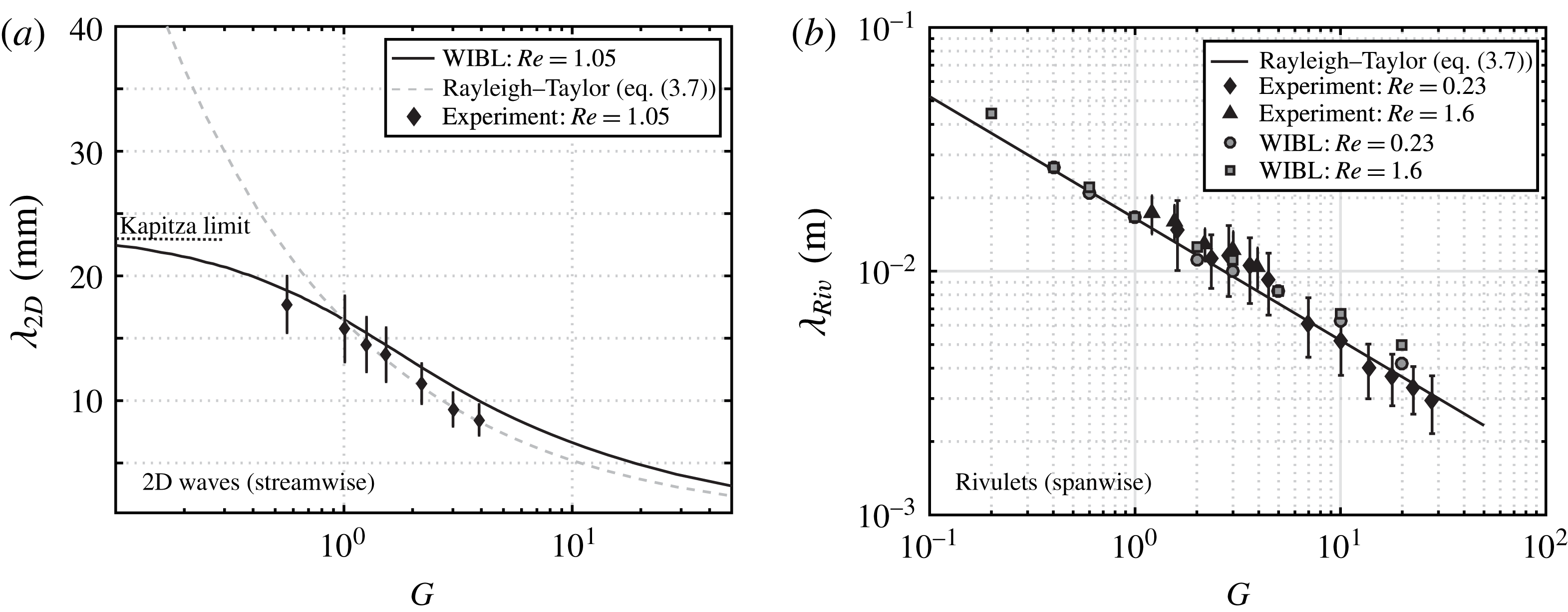
Results for the case of 2-D waves are presented in figure 7(a). Due to the Reynolds number dependency of the full second-order model (equation (3.1)) exemplary results are shown for one Reynolds number only (
 $Re=1.05$
), which corresponds to the case displayed in § 3.1. A good match between experimental data and most amplified wavelength predicted by the WIBL model is found, with maximal deviations of approximately 1 mm. In fact, slight deviations between experimentally observed data and predictions from the temporal stability analysis of the full dispersion relation are expected due to several reasons. First, it is reasonable to assume that due to the convective nature of the instability a spatial amplification might be of significance. Additionally, system specific mechanical excitation might influence wavelength selection. Under this premises, the match between experimental results and WIBL model is very good. In fact, the match indicates that the two aforementioned error sources are not that significant, given the small difference between the wavelength predicted by the WIBL model and experimental data. The transition from a dominating Kapitza instability to a dominating Rayleigh–Taylor instability is captured by the WIBL model and illustrated by the convergence to the Rayleigh–Taylor limit, which assumes no flow along the wall and thus no Kapitza type instability.
(a) Experimentally obtained wavelength of 2-D waves, most amplified wavelength predicted by the dispersion relation of the full second-order boundary layer model (equation (3.1)) and most amplified wavelength of the Rayleigh–Taylor instability. For
 $G\rightarrow 0$
, the WIBL model describes the pure Kapitza instability. (b) Comparison of experimentally and numerically obtained rivulet wavelength and most amplified wavelength of the Rayleigh–Taylor instability. Simulation results are obtained with an integral boundary layer model (WIBL (Ruyer-Quil & Manneville Reference Ruyer-Quil and Manneville2000; Scheid, Ruyer-Quil & Manneville Reference Scheid, Ruyer-Quil and Manneville2006), see figure 8).

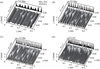
Simulation results obtained with the full weighted integral boundary layer model (WIBL) (Ruyer-Quil & Manneville Reference Ruyer-Quil and Manneville2000; Scheid et al.
Reference Scheid, Ruyer-Quil and Manneville2006) showing rivulet structures for low values of
 $G$
(0.2, 0.4, 0.6, 1),
 $Re=1.6$
and
 $Ka=5.1$
.

In figure 7(b), experimentally obtained data of the rivulet wavelength for two Reynolds numbers are compared to the most amplified wavelength predicted by linear stability analysis (Rayleigh–Taylor, equation (3.7)). Experimental data agree very well with the theoretical predictions. Indeed, the results illustrate that the spanwise modulation of the film surface into rivulets is independent from the streamwise flow for the Reynolds numbers investigated. Unfortunately, no experimental data for the rivulet wavelength are available for low values of
 $G$
, because the inception length surpasses the size of the experimental set-up for
 $G<0.8$
(see figure 6). Hence, in order to extend the experimental results to low destabilizing body forces, supporting simulations of the film evolution using the full integral boundary layer (WIBL) model have been performed. Derivation and utilization of the WIBL model are comprehensively introduced for example in Scheid et al. (Reference Scheid, Ruyer-Quil and Manneville2006). The computational domain of size
 $L_{x}\times L_{z}$
(
 $0.07~\text{m}\times 0.4~\text{m}$
) is discretized with
 $M\times N$
(
 $128\times 512$
) regularly spaced grid points and periodic boundary conditions are employed in streamwise and spanwise directions. The time scale for the problem is given in Shkadov scaling (Kalliadasis et al.
Reference Kalliadasis, Ruyer-Quil, Scheid and Velarde2012) with
 $t=\unicode[STIX]{x1D705}\unicode[STIX]{x1D708}/g\bar{h}_{N}$
including the scaling factor
 $\unicode[STIX]{x1D705}=(\unicode[STIX]{x1D70E}/\unicode[STIX]{x1D70C}g\bar{h}_{N}^{2})^{1/3}$
. Fluid properties match the experimental study and the imposed flow rates corresponds to
 $Re=0.23$
and
 $Re=1.6$
. The Nusselt flat film solution was chosen as initial condition for the simulations and an initial noise level with a standard deviation of 1 % of the flat film thickness was applied to the film height. Exemplary cases for
 $G=(0.2,0.4,0.6,1)$
and
 $Re=1.6$
are shown in figure 8 for a given time
 $t$
, while values of the average rivulet wavelength for all investigated cases are reported in figure 7. Simulations confirm the prediction for the rivulet wavelength from linear theory for low values of
 $G$
. Thus, equation (3.7) adequately describes the spanwise structuring of the film surface, confirming that rivulet formation is a direct consequence of a destabilizing body force in the form of a wall normal acceleration. Adding to this, the development of rivulet structures for low values of
 $G$
(figure 8
a) suggests that spanwise structuring occurs for any non-zero
 $G$
after a sufficiently long time, as proposed by linear arguments. Note that together with an increasing wavelength for decreasing
 $G$
, the width of single rivulets is increasing, which is assumed to have a significant influence on the stability of solitary waves on rivulets and therefore the occurrence of dripping (Indeikina et al.
Reference Indeikina, Veretennikov and Chang1997).
We mention here that the WIBL model in its usual form does not show any spatially localized numerical singularities which could correspond to droplet detachment events. In other words, a stationary solution exists for any values of the control parameters and the model loses accuracy close to the dripping limit (Rohlfs et al. Reference Rohlfs, Pischke and Scheid2017).
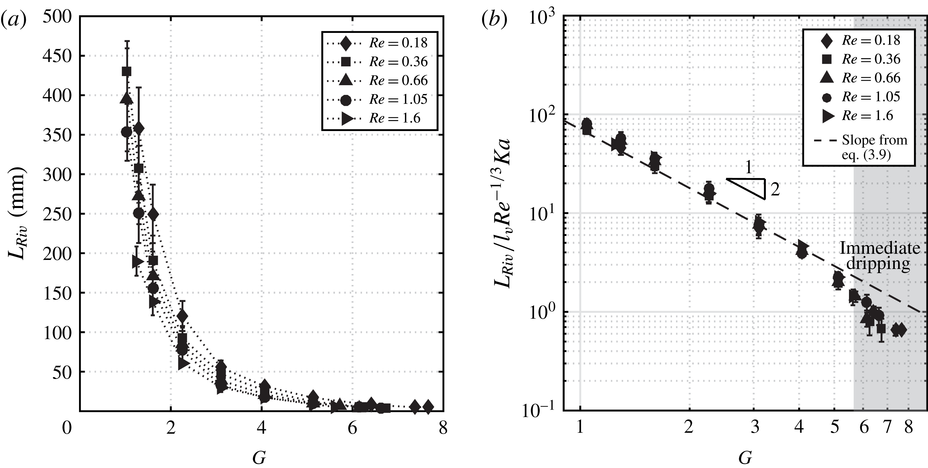
Inception length of rivulets structures observed experimentally. (a) Dimensional values for the inception length
 $L_{Riv}$
in dependence of
 $G$
. (b) Non-dimensional inception length of rivulet structures in logarithmic representation.

3.3.2 Rivulet inception length
In order to examine the relation between rivulet inception length and control parameters
 $G$
and
 $Re$
, the beginning of the rivulet regime as observed in experiments has been tracked. Results are shown in figure 9. At this point, simulation results for the inception length are not shown due to unknown initial noise levels within the experiment, which prevents comparability of experiment and simulation. Additionally, as droplet detachment cannot be resolved with the employed model, no numerical results are obtainable for higher values of
 $G$
, where dripping events heap up.
In figure 9(a), dimensional results for the rivulet inception length are illustrated for Reynolds numbers between
 $Re=0.18$
and
 $Re=1.6$
. Cut-off values for the parameter
 $G$
result from the absence of rivulet structures within the experimental test section (low
 $G$
) and the onset of immediate dripping (high
 $G$
).
Since the rivulet wavelength was shown to be captured by linear analysis, it is expected that the associated inception length is intimately related to the corresponding growth rate
 $\unicode[STIX]{x1D6FE}_{i,max}$
(equation (3.8)). From this growth rate a characteristic time scale corresponding to the Rayleigh–Taylor instability
 $\unicode[STIX]{x1D70F}_{Riv}$
can be constructed as
 $\unicode[STIX]{x1D70F}_{Riv}=1/\unicode[STIX]{x1D6FE}_{i,max}$
. A characteristic length scale, corresponding to the distance the film has travelled within the characteristic time scale of the Rayleigh–Taylor instability, is then obtained by multiplying
 $\unicode[STIX]{x1D70F}_{Riv}$
with the Nusselt average velocity
 $\bar{u}_{N}=Re(\unicode[STIX]{x1D708}/\bar{h}_{N})$
. Assuming proportionality between this length scale and the rivulet inception length leads to
 $$\begin{eqnarray}\displaystyle L_{Riv} & \propto & \displaystyle \unicode[STIX]{x1D70F}_{Riv}\bar{u}_{N}\nonumber\\ \displaystyle & \propto & \displaystyle \frac{\unicode[STIX]{x1D70E}\unicode[STIX]{x1D708}}{\bar{h}_{N}^{3}\unicode[STIX]{x1D70C}g^{2}}G^{-2}Re\frac{\unicode[STIX]{x1D708}}{\bar{h}_{N}}\nonumber\\ \displaystyle & \propto & \displaystyle l_{\unicode[STIX]{x1D708}}Re^{-1/3}G^{-2}Ka.\end{eqnarray}$$
Using the proportionality expressed in (3.9), the data sets collapse in a logarithmic representation (figure 9
b). Both the predicted Reynolds dependency and the dependency from the parameter
 $G$
are confirmed by experimental data. A deviation is found within the zone of immediate dripping, where, independently from the magnitude of
 $G$
, the detachment in the form of evenly spaced droplets occurs right at the fluid inlet. Since the Kapitza number combines fluid properties, it is suggested that the scaling remains valid for other working fluids, even though it has not been tested experimentally in the present study.
3.3.3 Dripping mechanisms and the convective/absolute instability transition
In the previous section, a continuous evolution of 2-D waves and rivulet structures in good agreement with linear stability analysis has been found with respect to the wavelength of 2-D waves as well as rivulet wave and inception lengths. At the same time, dripping events, associated with the rivulet regime, have been found to display a discontinuous evolution. Sharp distinctions between dripping events characterized by growth or interaction of solitary pulses on rivulets at an arbitrary distance from the fluid inlet, the formation of a distinct dripping zone and immediate dripping (see figure 5) have been observed. As linear stability analysis predicts a regime change corresponding to a transition from a convective to an absolute type of instability (Brun et al. Reference Brun, Damiano, Rieu, Balestra and Gallaire2015; Scheid et al. Reference Scheid, Kofman and Rohlfs2016) (C/A transition) for the problem in question, a comparison of the predicted regime boundary to experimental observations of dripping is carried out.
The analysis is analogous to the theoretical considerations of Scheid et al. (Reference Scheid, Kofman and Rohlfs2016). In this context, the C/A transition is defined by the marginal mode with zero group velocity that solves the dispersion relation derived from the full second-order (WIBL) model (equation (3.1)). Note, that the derivations of Scheid et al. (Reference Scheid, Kofman and Rohlfs2016) assume the film flow under an inclined plane. Hence, the calculations have been adjusted for the case of a rotating cylinder with negligible curvature by applying the transformations introduced in (2.1) and (2.2). The location of the transition in dependence of the control parameters
 $G$
and
 $Re$
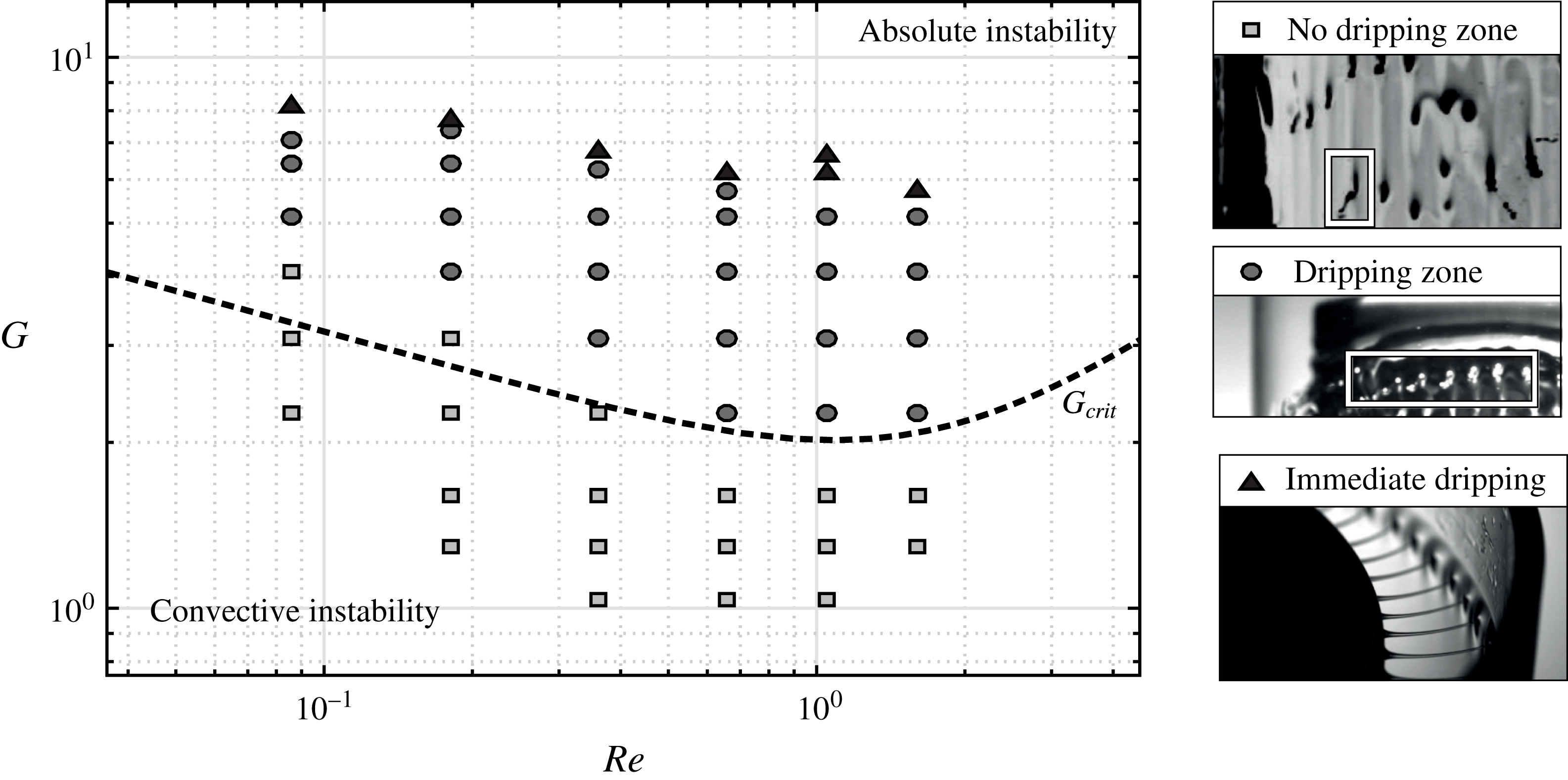
is shown in figure 10 (dashed line) within the parameter range of the experiments. Note that the predicted non-monotonic character of the C/A transition is not fully captured due to the current flow rate limitation of the experimental set-up. The experimentally found predominant dripping mechanisms are indicated by the respective symbols.
Comparison between the transition from a convective to an absolute type of instability (
 $G_{crit}$
, dashed line) (Scheid et al.
Reference Scheid, Kofman and Rohlfs2016) and the character of the predominantly observed dripping mechanism in the experiments (symbols).

Most notably, the transition to an immediate dripping state (triangles) takes place far beyond the absolute instability threshold. At the same time, the emergence of a dripping zone (circles), where droplet detachment occurs immediately after destabilization of 2-D wavefronts into rivulets, is found to begin right after the transition to absolute instability. This observation is assumed to coincide with the increasing number of droplets, which were observed beyond the transition to absolute instability in the recent study of Brun et al. (Reference Brun, Damiano, Rieu, Balestra and Gallaire2015). However, the correlation between the transition to absolute instability and the formation of a dripping zone is observed to be weaker for lower Reynolds numbers (see figure 10), so that a direct connection between the two cannot be confidently stated. In fact, it remains questionable whether linear arguments can predict the character of dripping to be predominantly observed in experiment provided the nonlinear character of dripping events, especially when it arises from wave coalescence and interaction. In this regard, a more detailed analysis of the stability of single rivulets and the competition between the Rayleigh–Taylor instability and secondary instabilities of the 2-D wavefronts should be undertaken in a future work.
4 Conclusion
Flow and dripping phenomena of a falling liquid film under the influence of a destabilizing body force have been experimentally investigated. More specifically, the evolution of a falling film on the outside of a vertically oriented rotating cylinder was examined in dependence of the control parameters, namely Reynolds number and body force ratio
 $G$
comparing the centrifugal acceleration acting perpendicular to the film flow and the gravitational acceleration acting parallel to the flow. Shear at the liquid/air interface has been suppressed through an outer, co-rotating cylinder. High speed visualization was used to capture the film surface topology within the experimental parameter range for the Reynolds number (
 $Re<1.6$
), rotation frequency
 $f$
(
 $f<8~\text{Hz}$
) and the employed working fluid (
 $Ka=5.1$
).
Increasing the magnitude of the destabilizing body force (increasing
 $G$
), a transition from a film flow dominated by the Kapitza instability to a film dominated by the Rayleigh–Taylor instability is most notably observed as a continuous decrease of the inception length of rivulet structures and a discontinuous evolution of the predominant dripping mechanism.
Wavelength as well as inception length of developing rivulet structures match the predictions from linear stability analysis of the classical Rayleigh–Taylor problem. In this context, the control parameter dependency of the rivulet wavelength is given with
 $\unicode[STIX]{x1D706}_{Riv}\propto l_{\unicode[STIX]{x1D708}}G^{-1/2}Ka^{1/2}$
(see (3.7)). The inception length of rivulet structures follows
 $L_{Riv}\propto l_{\unicode[STIX]{x1D708}}G^{-2}Re^{-1/3}Ka$
(see (3.9)). The development of rivulet structures for low destabilizing body forces has been shown through supporting numerical simulations of the film evolution with an integral boundary layer model (Ruyer-Quil & Manneville Reference Ruyer-Quil and Manneville2000). This finding, in combination with the observation of dripping events due to interactions of solitary waves on rivulets leads to the conclusion that dripping might be expected for any non-zero value of the destabilizing body force after a sufficiently long evolution length.
The discontinuous evolution of the predominant dripping mechanism is, for increasing values of
 $G$
, first observed as a transition from localized dripping occurring from wave coalescence and interaction events on rivulets to the formation of a distinct dripping zone immediately after the destabilization of 2-D waves into rivulets. Subsequently, the inception length of the dripping zone decreases until finally a state of immediate fluid detachment at the inlet is reached. The concentration of liquid in rivulet structures is found to be the predominant cause for a destabilization of the flow leading to droplet detachment. In fact, dripping is only observed subsequently to the emergence of rivulets.
Comparing the discontinuous evolution of dripping mechanisms to the transition from a convective to an absolute instability as predicted by linear stability analysis shows partial agreement: the emergence of a distinct dripping zone roughly coincides with the transition to absolute instability within the investigated range of the Reynolds number. At the same time, the onset of immediate dripping at the fluid inlet lies well beyond the predicted C/A transition. Hence it is shown that in order to accurately characterize and predict observed dripping mechanisms, a more detailed investigation of the stability of rivulet structures is necessary going beyond traditional linear arguments and including nonlinear interactions between Kapitza and Rayleigh–Taylor instabilities.
Acknowledgements
Funding for M.R. was provided by the HITEC (Helmholtz Interdisciplinary Doctoral Training in Energy and Climate Research) graduate school. B.S. thanks the F.R.S.-FNRS and the IAP-7/38 MicroMAST project for financial support.
Appendix A. Experimental parameters and conditions

Appendix B. Derivation of the dispersion relation (equation (3.1))
Equation (3.1) is the linear dispersion relation corresponding to the full second-order (WIBL) model introduced by Ruyer-Quil & Manneville (Reference Ruyer-Quil and Manneville2000, Reference Ruyer-Quil and Manneville2002) written in Nusselt scaling. It is taken from the monograph by Kalliadasis et al. (Reference Kalliadasis, Ruyer-Quil, Scheid and Velarde2012). The complete expression of the full second-order model is additionally found in recent publications (Scheid et al. Reference Scheid, Kofman and Rohlfs2016; Rohlfs et al. Reference Rohlfs, Pischke and Scheid2017) and not explicitly shown here. From the full model, equation (3.1) is derived by considering normal mode perturbations around the dimensionless Nusselt flat film solution in the form:
 $$\begin{eqnarray}\displaystyle h=1+a\text{e}^{\text{i}(kx-\unicode[STIX]{x1D6FE}t)}, & & \displaystyle\end{eqnarray}$$
 $$\begin{eqnarray}\displaystyle q={\textstyle \frac{1}{3}}+b\text{e}^{\text{i}(kx-\unicode[STIX]{x1D6FE}t)}, & & \displaystyle\end{eqnarray}$$
where
 $k=k_{r}+\text{i}k_{i}$
and
 $\unicode[STIX]{x1D6FE}=\unicode[STIX]{x1D6FE}_{r}+\text{i}\unicode[STIX]{x1D6FE}_{i}$
are dimensionless complex wavenumber and dimensionless complex angular frequency,
 $a,b$
are amplitudes of the perturbation and
 $h,q$
are dimensionless film thickness and flow rate. Inserting equations (B 1) and (B 2) into the full model, linearizing for small amplitudes
 $a,b$
and writing the expression in Nusselt scaling leads to the given dispersion relation.
Appendix C. Determination of characteristic length scales based on high speed recordings
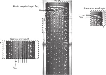
Experimental results presented in § 3.3 are based on the evaluation of a large number of single frames taken from high speed recordings of the film flow on the rotating cylinder. The exemplary evaluation of a single frame is illustrated in figure 11.
Measurement of characteristic length scales based on high speed recordings. Exemplary evaluation of the case
 $G=2.19$
and
 $Re=1.05$
.

The wavelength of 2-D waves (streamwise wavelength), the rivulet wavelength (spanwise wavelength) and the rivulet inception length are manually extracted from the recordings. As illustrated, multiple values for the streamwise and spanwise wavelength are recovered from one image as well as a single value for the rivulet inception length. For each measurement point presented in § 3.3 multiple single frames (
 ${>}$
50 frames) have been correspondingly evaluated. Sample mean and associated standard deviation are derived from the resulting data set.