I. INTRODUCTION
Over the past few decades, radio frequency identification (RFID) has been considered as a hot topic among researchers, due to its wide variety of application from automotive, aerospace and aviation to telecommunications, medical technology, and food traceability [Reference Bolic, Simplot-Ryl and Stojmenovic1]. Four frequency bands have been authorized for RFID systems: low-frequency (LF) 125–135 KHz, high-frequency (HF) 13.56 MHz, ultra-high-frequency (UHF) 860–960 MHz, as well as super-high frequencies (SHF) 2.45, 3.6, and 5.8 GHz [Reference Paret2, Reference Jones and Chung3]. The performance of the RFID systems is highly dependent upon the efficiency of the antenna; hence, employing a proper-designed antenna in such systems is so crucial [Reference Karmakar4]. Characteristics such as compactness, robustness, ease of fabrication, omnidirectional/hemispherical patterns, and long lifetime are considered as the most prominent features in RFID antenna design [Reference Bolic, Simplot-Ryl and Stojmenovic1, Reference Karmakar4, Reference Chen5]. Among all the mentioned properties, compactness is the most important feature in RFID application, since tags need to be easily attached to the desired objects [Reference Chen5].
Various techniques have been proposed for size reduction of the microstrip-based components. Fractal geometry [Reference Lotfi-Neyestanak and Lalbakhsh6–Reference Lalbakhsh, Neyestanak and Naser-Moghaddasi10], appropriately folding conventional structures [Reference Sundaram, Maddela and Ramadoss11] and the use of metamaterials [Reference Morgado12–Reference Hafezifard, Naser-Moghadasi, Rashed and Sadeghzadeh14] can be considered as some of the effective techniques for electromagnetic components miniaturization. The theoretical aspect of creation of resonances by microstrip-based structures was explained in [Reference Karimi, Lalbakhsh and Siahkamari15].
According to the aforementioned RFID antenna requirements, log-periodic dipole array (LPDA) antenna is considered as a good candidate for reader/tag antenna in the RFID systems. Traditionally, patch antennas are employed in RFID systems due to their design simplicity; however, these type of antennas produce a narrow bandwidth [Reference Karmakar4, Reference Hafezifard, Naser-Moghadasi, Rashed and Sadeghzadeh14]. LPDA antennas fall in the category of frequency-independent antennas and their configuration is very similar to the Yagi–Uda antennas, but they provide wider frequency bandwidth [Reference Johnson and Jasik16, Reference Huang and Boyle17]. The most significant features of the LPDA antennas are: parallel linear dipole elements, possessing different lengths and spacing, directional patterns with linear polarization, and relatively high directivity [Reference Harish and Sachidananda18], which helps to enhance the read range and reduce multi-path effects [Reference Bolic, Simplot-Ryl and Stojmenovic1, Reference Karmakar4]. For example, direction-of-arrival estimation in a directional RFID antenna has been used to improve the RFID positioning performance in a multi-path environment [Reference Mohamedatni, Fergani, Laheurte and Poussot19, Reference Ascher, Lechner, Nosovic, Eschlwech and Biebl20]. Considering the location and orientation of tags, which are predetermined in a typical RFID system, directional antennas are better candidates compared with their omnidirectional counterparts [Reference Karmakar4].
In this paper, three effective techniques are introduced to improve the conventional LPDA antennas. These techniques include a miniaturization technique, which uses a dynamic scaling factor for the first time, folding technique for front-to-back (F/B) ratio improvement and coupled feeding mechanism for input impedance matching enhancement. The rest of the paper is organized as follows: in Section II, a standard LPDA antenna is designed using conventional design procedure, which is later miniaturized in Section III, resulting in 51.5% length size reduction. The antenna is then restructured by applying a folding technique, explained in Section III, to significantly increase F/B ratio. Finally, a coupled feed with an open stub is used to achieve a good impedance matching. The simulated and measured results are discussed in Sections IV and V gives a brief conclusion of the paper.
II. STANDARD LPDA ANTENNA
In the proposed design, the operating frequency of 5.8 GHz is selected, which is defined as backscatter frequency in RFID systems. Therefore, this frequency can be used in readers and tags (e.g. semi-active or passive). The SHF band is desired, due to its highest data-transfer rate and its ability to be used for long range between the tag and the reader. Additionally, the antenna size is smaller in this band compared with other authorized frequency bands for RFID application [Reference Karmakar4, Reference Chen5].
Considering the existing trade-off between gain and antenna size along with the requirement of compactness in RFID systems, 7 dB directivity is chosen for this design. To achieve 7 dB directivity from a standard LPDA antenna, scaling factor (τ) and spacing factor (σ) were determined by Carrel's table [Reference Balanis21]. The obtained values are: τ = 0.8 and σ = 0.14, which give the apex angle of 19.56° by
 $$\alpha = \mathop {\tan ^ {-1}} \Big [\displaystyle{{1 - \tau} \over {4\sigma}} \Big] = 19.65^ \circ. $$
The lengths of the longest and shortest dipole elements in LPDA antennas are determined according to the following bandwidths. Desired bandwidth (B), active region bandwidth (Bar), and designed bandwidth (Bs), which are calculated by (2)–(4).
 $$B = \displaystyle{{f_{max}} \over {f_{min}}} = 1.52,$$
 $$B_{ar} = 1.1 + 7.7(1 - \tau )^2\displaystyle{{4\sigma} \over {1 - \tau}} = 1.97,$$
 $$B_S = B \times B_{ar} = 3,$$
where f min and f max in (2) are the lower and upper operating frequencies of the desired bandwidth, respectively. The number of LPDA antenna dipole elements (N) are then determined by
 $$N = 1 + \displaystyle{{{\rm log} \; (B_S)} \over {{\rm log} \; (1/\tau )}} = 6.$$
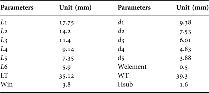
The length of first dipole element (L 1) in the LPDA antenna is calculated by (6), and then other five series dipole lengths are determined by (7) and tabulated in Table 1.
 $$L_1 = \displaystyle{c \over {f_{min}}},$$
 $$L_{n + 1} = \tau \times L_n,$$
where c is the free-space velocity of light and (L n) is the length of the nth element. Separation between every adjacent element (d n) is yielded by
 $$d_n = 2 \times \sigma \times L_n.$$
Dimensions of the standard LPDA antenna for τ = 0.8, σ = 0.14.

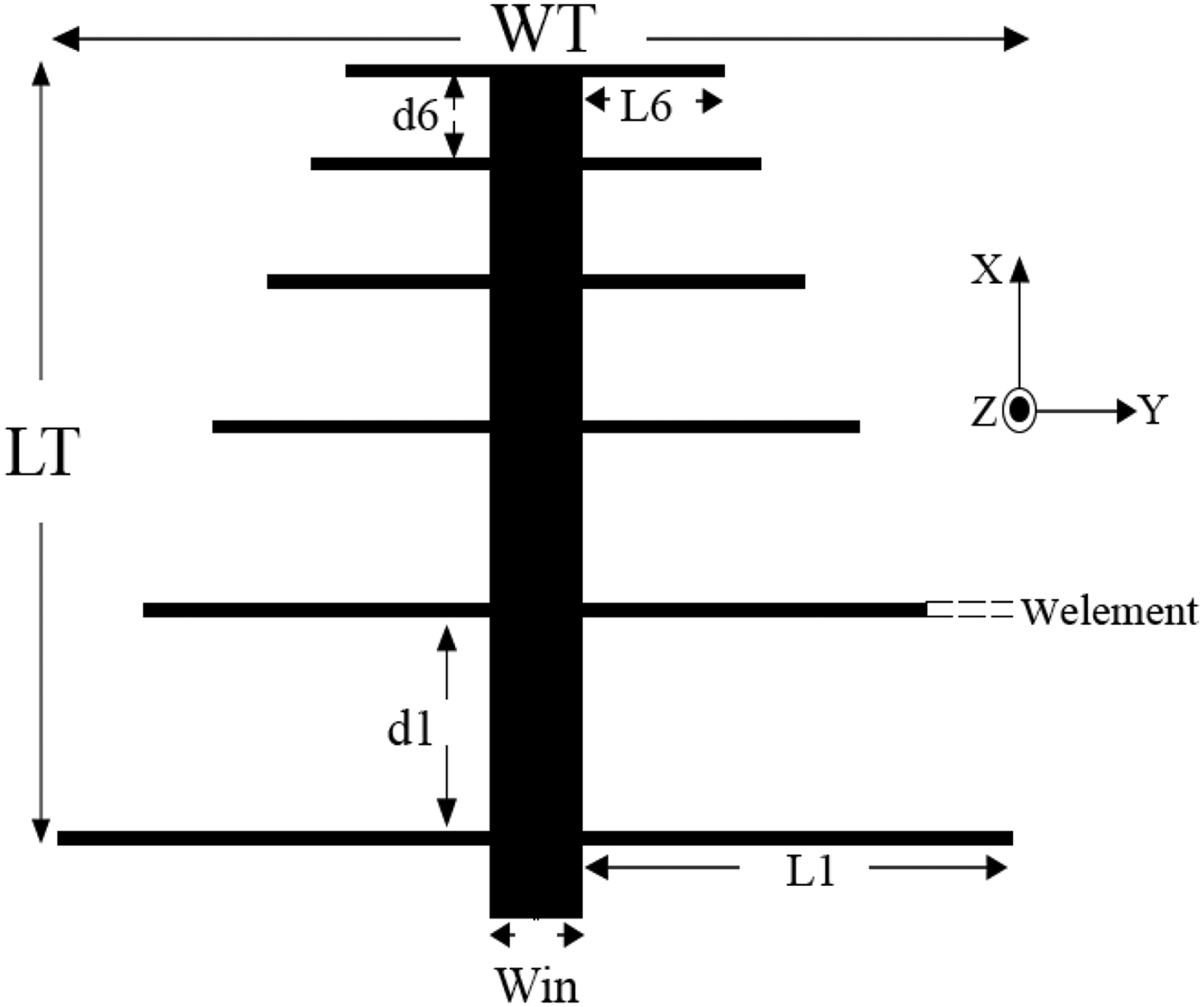
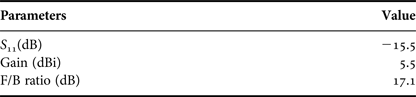
All design parameters for the standard LPDA antenna operating at 5.8 GHz are given in Table 1. The classical LPDA antenna, shown in Fig. 1, is printed on a RO4003 slab with thickness of 1.6 mm. A 50 Ω SubMiniature version A (SMA) connector is used to feed the antenna. Simulation of the standard LPDA antenna was carried out in High Frequency Structure Simulator (HFSS) and predicted results are summarized in Table 2.
Geometry of the standard LPDA antenna.

Results of the standard LPDA antenna.

III. PROPOSED ANTENNA
In Section II, the initial LPDA antenna operating at 5.8 GHz for RFID application was designed. Despite the straightforward design methodology, the presented conventional LPDA antenna fails to perfectly satisfy all RFID requirements. The structure is relatively big and the F/B ratio is 17.1 dB, which can still be improved. The input impedance is also not perfectly matched (S 11 = −15.5 dB). Therefore, to improve the antenna performance and make it quite practical for RFID uses, three techniques are proposed as follows:
(1) Miniaturization: introduction of the dynamic scaling factor (τ n) and a constant separation distance for the purpose of miniaturization.
(2) Folding technique: introduction of a folding technique to increase the F/B ratio of an antenna.
(3) Coupling feed mechanism: introduction of a proximity coupling technique to optimize the input impedance matching.
A) Miniaturization
In order to miniaturize the conventional LPDA antenna designed in Section II, a constant separation between every two adjacent dipole elements is proposed. In other words, instead of using (8) to calculate the gap between dipoles, a constant distance of G = 1 mm is considered between dipole elements in the proposed LPDA antenna configuration. This re-arrangement reduces the boom length of the antenna by 51.5%, resulting in shifting operating frequency to a higher frequency. To re-tune the centre frequency, a dynamic scaling factor (τ n), as opposed to constant scaling factor in the conventional LPDA antenna, is proposed. More precisely, variable scaling factors are used to achieve the required bandwidth and gain. The dipoles lengths are then updated by
 $$L_{n + 1} = \tau _n \times L_n.$$
The chosen scaling factors for dipoles are tabulated in Table 3 as following;
Scaling factors (τ n) used between the adjacent elements.

B) Folding technique
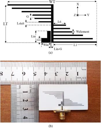
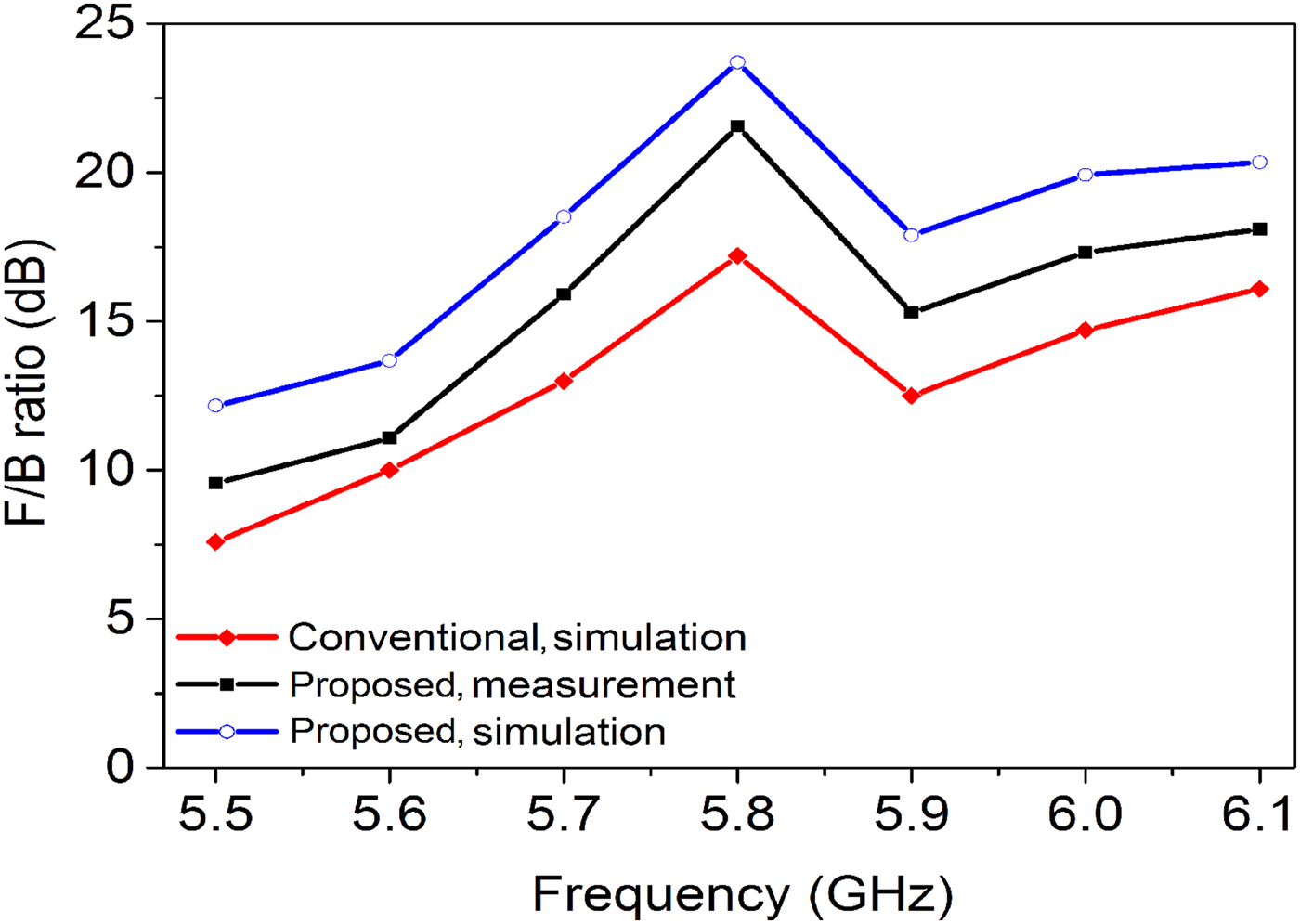
A novel approach, named folding technique, is proposed to improve F/B ratio, which is a very important index for directional antennas. Different passive and active methods have been proposed to improve this index [Reference Huang and Hsu22–Reference Cheng, Ding, Wang and Shao24]. The introduction of reflectors at lower frequency bands and directors at higher frequency bands was investigated in [Reference Huang and Hsu22] for the F/B ratio enhancement. The well-known split ring resonators and complementary split ring resonators were proposed to be employed as radiating elements to improve the F/B ratio [Reference Kim, Yoon, Yoon, Lee and So23]. In a different approach, application of active devices was also proposed for such a purpose [Reference Cheng, Ding, Wang and Shao24]. Here, we propose a passive simple technique which neither enlarges the antenna nor needs defecting the ground of the antenna. In our technique, the antenna is folded relative to the x-axis, as depicted in Fig. 2, improving the F/B ratio from 17.1 to 21.5 dB at the resonance frequency (5.8 GHz). This enhancement versus frequency is later shown in Section IV, where the results will be discussed.
Proposed antenna. (a) Layout of the antenna. (b) Photograph of the antenna.

C) Coupling feed mechanism
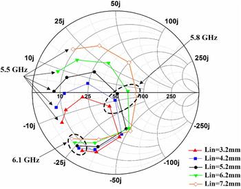
One of the main challenges with the conventional printed-LPDA antennas is to achieve a good impedance matching without sacrificing the compactness and the overall performance of the antenna. Baluns can be used for a better impedance matching at the price of larger size [Reference Zhang, Wu, Liu, Yu and Chen25–Reference Zhang and Zhihong27]. Coaxial cables were also mostly used in wideband applications to feed these types of antennas [Reference Chauloux, Colombel, Himdi, Lasserre and Pouliguen28, Reference Bishop, Miller, Zeppettella, Baron, Tuss and Ali29]. A coupling method using multi-substrates was also utilized in [Reference Amini and Oraizi30]. Here, we propose a simple feeding system which not only increases the size and complexity of the antenna, but also improves the impedance matching in terms of bandwidth and level. In our feeding system, a coupled feed with an open stub, as shown in Fig. 2(a), are used to provide more flexibility for a better impedance matching. The input reflection coefficient is dominantly controlled by the length of the coupling path (Lin). Smith chart in Fig. 3 shows the input impedance values of the RFID antenna for different lengths of Lin in a frequency range of 5.5–6.1 GHz.
Input impedance of the proposed antenna for frequency swept from 5.5 to 6.1 GHz versus coupling path length (Lin).

Based on Smith chart results, shown in Fig. 3, the best impedance matching close to 50 Ω at the operating frequency of the LPDA antenna (5.8 GHz) is achieved for Lin = 5.2 mm. The recorded impedance value from SMD port (Zant) is equal to 52−j1.4.
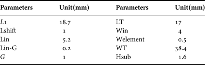
The geometrical parameters of the final LPDA antenna are given in Table 4. The layout and the fabricated prototype of the RFID antenna are shown in Figs 2(a) and 2(b), respectively. The antenna was fabricated on a grounded RO4003 substrate (εr = 3.38, δ = 0.002), with the dielectric and metal thicknesses of 1.6, 0.035 mm, respectively. The overall dimension of the substrate is 30 × 45 mm2 (0.58λ0 × 0.87λ0).
Dimensions of the proposed antenna.

IV. DISCUSSION AND RESULTS
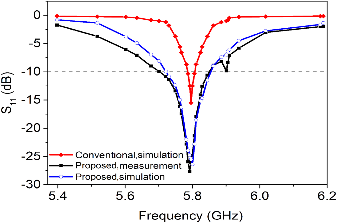
All simulations were carried out by Ansoft HFSS 14 software using Finite Element Method (FEM) analysis. Measured and simulated reflection coefficients are shown in Fig. 4. The measured S 11 at the operating frequency of the RFID antenna is −28 dB with 3.4% 10-dB fractional bandwidth, showing an excellent input impedance matching. It can be seen from this figure that the return loss at 5.8 GHz has been increased by 12.5 dB due to the application of coupled feed. Similarly, The 10-dB return loss fractional bandwidth has also increased from 1 to 3.4%. Figure 5 compares F/B ratio of the designed RFID antennas for the standard and proposed cases. The folding technique has improved F/B ratio of the antenna from 17.1 to 21.5 dB, which is significantly higher compared with the other presented works [Reference Hsu and Huang8, Reference Syed and Neto31, Reference Estrada, Paez and Fajardo32].
The input reflection coefficient of the standard LPDA and the proposed antenna.

F/B ratio of the standard LPDA and the proposed antenna. The maximum value of 21.5 dB is obtained at the frequency of 5.8 GHz.

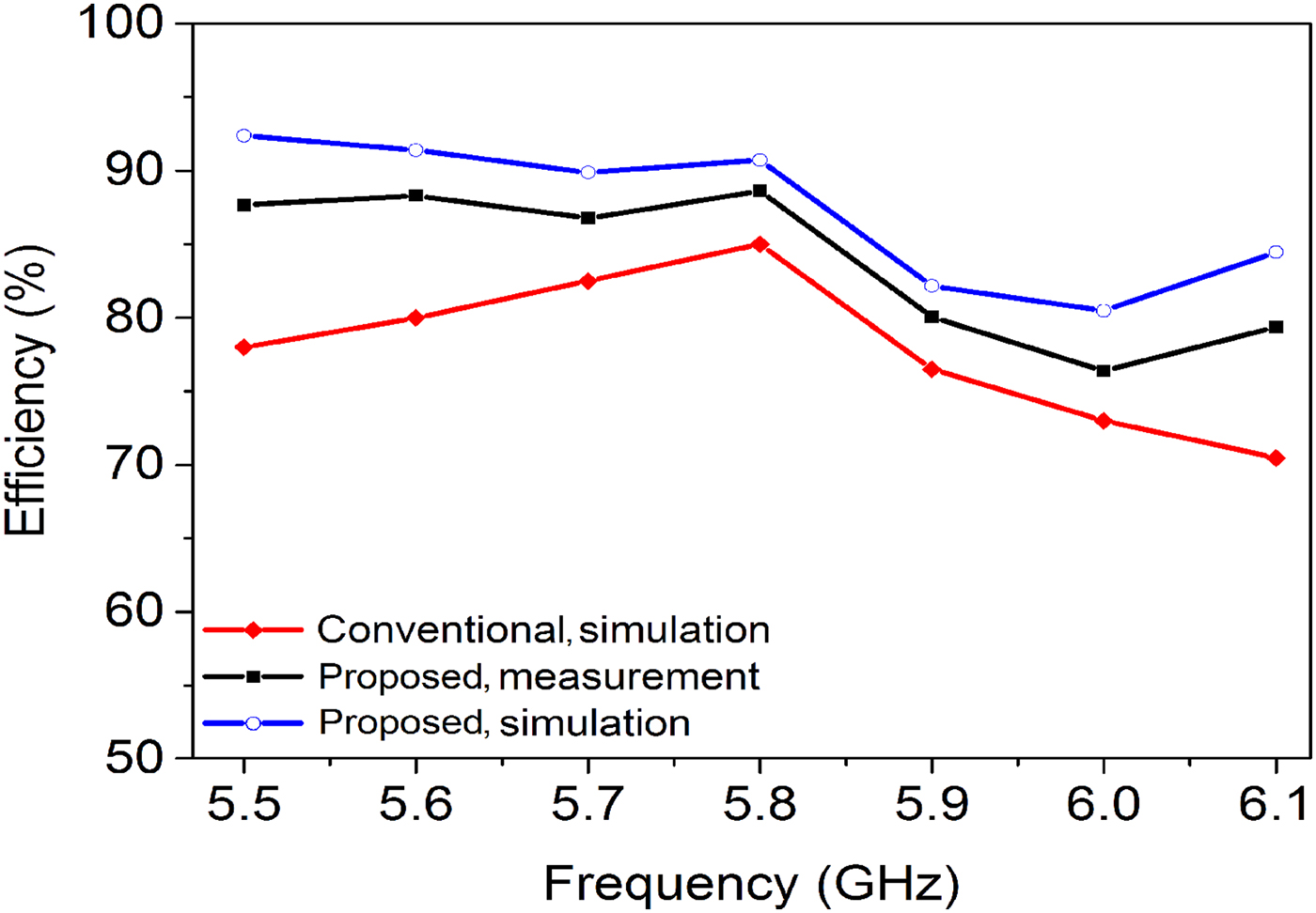
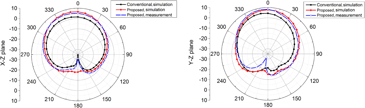
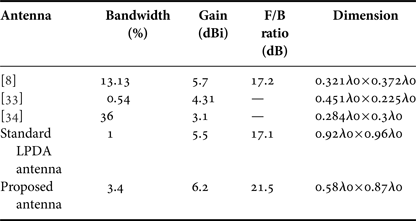
Measured radiation efficiency of the prototype at 5.8 GHz is 90%, while this is 85% for the standard case, as shown in Fig. 6. Far-field radiation patterns (gain) of the antenna in two planes at 5.8 GHz are shown in Fig. 7, exhibiting very good agreement between simulated and measured results in both planes. The measured gain at 5.8 GHz is 6.2 dBi. Also, the 3 dB beamwidth for the X–Z plane is 101° and for the Y–Z plane is 89°, showing a good directional characteristic. A performance comparison is made in Table 5 between the proposed antenna and some other works.
Antenna efficiency versus frequency of the standard LPDA and the proposed antenna.

Simulated and measured far-field radiation patterns of the standard LPDA and the proposed antenna at 5.8 GHz.

Performance comparison of the proposed RFID antenna and some of the latest previous works.

V. CONCLUSION
This paper presents a generalized approach to design a high-performance RFID antenna inspired by conventional LPDA. A novel miniaturization technique is proposed for LPDA class of antennas in which a dynamic scaling factor along with equally separated dipole elements are used. This technique has reduced the length of the LPDA antenna by about 52% compared with the conventional LPDA antenna. The final size of the antenna is only 30 × 45 mm2 (0.58λ0 × 0.87λ0). The fabricated antenna has a very good F/B ratio of 21.5 dB due to apllication of our folding technique. The application of the coupling feed along with an open stub in the feeding mechanism has resulted very good input impedance matching of −28 dB at the operating frequency (5.8 GHz). Regarding all desired features, the presented antenna is a very good candidate to be used in RFID systems. In addition, all three techniques explained in the paper to improve compactness, F/B ratio, and input impedance matching of LPDA antennas are not limited to RFID application and can be employed for other applications.
 Pourya Rostami Gooran was born in Kermanshah, Iran, in 1985. He received his B.Sc. degree in Electronic Engineering in 2008 from Islamic Azad University, Kermanshah Branch, Kermanshah, Iran and the M.Sc degree from Kermanshah Science and Research Branch, Islamic Azad University, Kermanshah, Iran, in 2015. His current research interests are RF/Microwave circuit design.
 Gholamreza Karimi received his B.S. and M.S., and Ph.D. degrees in Electrical Engineering from Iran University of Science and Technology in 1999, 2001, and 2006, respectively. He is currently an Associate Professor in Electrical Department at Razi University, Kermanshah, since 2007. His research interests include low-power analog and digital IC design, RF IC design, modeling, and simulation of RF mixed signal IC. He is also interested in microwave devices and artificial intelligence systems.
 Ali Lalbakhsh received his B.Sc. and M.Sc. degrees in Communication Engineering from Islamic Azad University, Boroujerd Branch, in 2008 and Islamic Azad University, Science and Research Branch in 2011, respectively. From 2010 he is a lecturer and researcher at Islamic Azad University, Kermanshah Branch. His research interests include Microwave passive components, antenna design, artificial intelligence, periodic, and electromagnetic band gap structures. Lalbakhsh is a member of Institute of Electrical and Electronics Engineers from 2011 and a reviewer for several journals of IEEE and IET.