Introduction
In the past decade, the wireless communication industry has been advancing significantly to support high data rates and low-latency applications. With the advent of 5G, low latency and high data rates are emerging as standard choices for the wireless communication industry to connect virtually everyone and everything together. From an application perspective, sub-6 GHz and millimeter wave (mm-wave) are the two primary bands into which 5G can be divided. These bands all have unique benefits [Reference Andrews, Buzzi, Choi, Hanly, Lozano, Soong and Zhang1]. The sub-6 GHz band can be used in applications such as multi-Gbps data rates and extensive coverage areas. It is at the equilibrium point between spectrum coverage and capacity that it provides a complete environment for the earliest 5G connectivity. Moreover, multiple input multiple output (MIMO) technology has become a popular choice and is currently used in numerous wireless communication standards. MIMO technology can support higher link reliability, data speeds, high throughput, low latency, and high channel capacity without requiring additional power or spectrum [Reference Ban, Li, Sim, Wu and Wong2, Reference Aldo3]. The stringent requirement in sub-6 GHz band applications requires advanced antenna technology, which is why MIMO antennas are a popular choice nowadays for antenna design for 5G applications.
As compared to the microstrip patch antenna, dielectric resonator antennas exhibit superior temperature stability, high gain, compact size, and radiation efficiency [Reference Singhwal, Ladislau, Kanaujia and Jugul4, Reference Mohammad5]. That’s why dielectric resonators are a popular option for antenna design and development. A MIMO dielectric resonator antenna includes the benefits of the MIMO system in combination with the benefits of a dielectric resonator antenna [Reference Singhwal, Ladislau, Kanaujia and Jugul4]. MIMO antenna technology based on DRA offers numerous advantages, including more antenna design freedom, low losses, less fading, improved coverage and connectivity, high throughput, and low latency [Reference Mohammad5]. In [Reference Singhwal, Kanaujia and Ajit6], a single-element MIMO DRA element is designed by combining an L-shaped DRA and CDRA, which has better impedance matching, high gain, and moderate isolation. A 2-port MIMO antenna, utilizing a rectangular dielectric resonator, has been developed to operate within the 2.56–2.64 GHz frequency band, achieving a minimum isolation of 20 dB through the placement of a slit in the ground plane, making it an ideal solution for Long-Term Evolution (LTE) applications [Reference Nasir, Jamaluddin, Khalily, Kamarudin and Ullah7]. In view of future wireless applications [Reference Kulkarni, Desai and Sim8], presents a high-performance 2-port MIMO antenna designed with high isolation and wide bandwidth. A circularly polarized (CP) broadband MIMO antenna based on DRA has been designed for WiMAX applications. The diagonal placement of the DRA, which simultaneously stimulates two orthogonal modes, and the parasitic patch improve isolation and CP [Reference Iqbal, Illahi, Sulaiman, Alam, Su’ud and Yasin9]. The wideband flexible antenna is proposed for applications in sub-6 GHz, 5G, and WLAN applications [Reference Desai, Palandoken, Kulkarni, Byun and Nguyen10]. In [Reference Girjashankar, Upadhyaya and Desai11], the dual-band hybrid MIMO DRA antenna is proposed for application in 5G and Wi-Fi 6. In [Reference Lin, Jamaluddin, Awang, Aju, Dahri, Yen and Rahim12] a tri-band MIMO antenna suitable for LTE band applications is introduced, which uses a combination of a meander line antenna and a rectangular dielectric resonator antenna. Due to the hybrid configuration, field propagation control is required to avoid back radiation from the antenna. Decoupling using the dielectric substrate above the array was also discussed in [Reference Min13] for the design of MIMO-based DRA. This approach is suitable for certain predetermined arrays, with the potential for the excitation of higher-order modes. Recently, there has been a surge in the development of cylindrical dielectric resonator-based MIMO antennas to improve diversity in wireless communication systems. A tri-band hybrid CDR-based MIMO antenna was proposed in [Reference Sharma, Das and Gangwar14] to cater to various frequency bands, including LTE bands (2.5–2.57 GHz, 2.62–2.69 GHz), WLAN (5.15–5.35 GHz, 5.725–5.825 GHz), and WiMAX (5.250–5.850 GHz). The design employed inverted L-strips and metallic strips to effectively separate the ground plane, thereby enhancing isolation between the antenna elements. A triple-band DRA-based MIMO radiator [Reference Das, Sharma and Gangwar15], suitable for various wireless applications, was designed using two C-shaped printed lines and a cylindrical dielectric resonator (CDR) with a defected ground structure (DGS). This configuration enables the production of two radiating modes in the CDRA. This antenna works in the frequency bands 1.86–2.6 GHz, 3.3–3.64 GHz, and 4.42–4.75 GHz. In [Reference Singhwal, Kanaujia, Ajit, Jugul and Matekovits16], a dual-band circularly polarized ring-type DRA-based MIMO antenna was proposed that operated in the 3.5 GHz and 5.5 GHz bands. This antenna provides circular polarization in both bands with good coverage and capacity. A dual-band CDRA-based MIMO operating in WLAN and WiMAX bands with isolation better than 20 dB and a gain of 6 dBi is designed by employing two orthogonally placed resonators excited by a rectangular slot loaded from a microstrip line [Reference Kumari, Das, Gangwar and Suman17]. In [Reference Bing, Jian, Yu-Xiang, Ying and Yingzeng18], a four-port compact CDRA-based MIMO operating on a 2.4 GHz wireless local area network (WLAN) is investigated using higher-order modes to obtain pattern diversity and polarization diversity. Probes coupled with two pairs of polarization-orthogonal slots can be used to excite two degenerate polarization-orthogonal modes. Similarly, in [Reference Nan and Leung Kwok19], pattern diversity-based CDRA was designed using mean-line-loaded annular slots and HEM and TM modes excited by a pair of differential strips for WLAN application. In [Reference Das, Sharma and Gangwar20], a wideband two-element dual-port hybrid MIMO ring DRA was designed to achieve a wide impedance bandwidth of 85.21% (3.3–8.2 GHz) with isolation better than 20 dB and a gain of 3 dB. However, little meaningful work has been carried out on MIMO DRA for the sub-6 GHz band in the literature. So, still, there are challenges to designing a DR antenna with a compact size, moderate or high gain, sophisticated feeding to control antenna radiation characteristics, good isolation, and excellent diversity performance for sub-6 GHz band communication systems. 5G handsets require a large number of antennas to boost spectral efficiency, which results in increased network coverage capacity and throughput. In [Reference Jaglan, Gupta, Kanaujia and Sharawi21, Reference Jaglan, Gupta and Sharawi22], the authors have designed a multiband antenna for smartphone applications that can be easily integrated with the subscriber’s handset.
In this paper, the authors designed a modified aperture-coupled CDR-based MIMO antenna for sub-6 GHz band applications. Deliberately choosing an aperture as the feed to excite the HEM11δ mode in CDR eventually results in a CDRA resonating at 3.5 GHz. Aperture coupling is used to excite the HEM11δ mode without the involvement of any hybrid mode. Aperture coupling also serves as a magnetic dipole to launch the HEM11δ mode in the CDR, which has a stable radiation pattern. To improve isolation between the antenna elements, a CDR-based MIMO antenna was proposed, where two identical antennas were placed side by side, separated by an asymmetric cross slot, resulting in an isolation enhancement of around 6 dB. The proposed CDR-based MIMO has a wide impedance bandwidth of 3.2–3.7 GHz. The isolation between the CDRAs in the proposed antenna is greater than 20 dB within the operating range, and the average gain is 4.7 dB. To evaluate various diversity performance parameters, the following metrics were used: envelope correlation coefficient (ECC), diversity gain (DG), and total active reflection coefficient (TARC) of the channel.
Basic MIMO antenna configuration
The design of the proposed cylindrical dielectric resonator antenna (CDRA) is shown in Fig. 1(a). The proposed CDR-based MIMO antenna consists of two CDRs positioned side by side, spaced 34 mm apart, and mounted on a RT-duroid substrate with a relative permittivity of 2.2, a loss tangent of 0.0009, and a thickness of 0.254 mm. Figure 1(b) and 1(c) displays the 3D view and top view of the proposed antenna, respectively. A cylindrical-shaped Eccostock HIK (εr = 10) material is chosen as the CDRA, designed to operate at 3.5 GHz. The CDRA has a radius of 13.5 mm and a height of 9.3 mm and is designed to operate in the sub-6 GHz band. The aperture coupling technique is used for feeding the CDRAs through a rectangular slot of dimension 10.6 × 2 mm2 etched from the top conductor layer of the RT Duroid substrate. To achieve improved impedance matching and coupling between the microstrip line and CDRA, an elliptical-shaped step impedance transmission line is placed underneath the rectangular slot, serving as a driven element. This design optimization involves carefully tuning the microstrip line and rectangular slot to maximize the coupling through the aperture. The slot dimension is calculated by using Eq. 1 and Eq. 2 [Reference Gupta, Guha and Kumar23, Reference Guha, Gupta and Kumar24]. All the dimensions of the CDR, slot, substrate, and modified microstrip feed line are listed in Table 1.
(a) The CDRA's basic construction, (b) the CDR-based MIMO antenna shown in three dimensions, and (c) the top view of the MIMO antenna.

 \begin{equation}{L_s} = 0.4{{\lambda }}/\sqrt {{{{\varepsilon }}_{\text{r}}}} ,\end{equation}
 \begin{equation}{W_s} = 0.2{L_s},\end{equation}
Dimensions involved in CDR-based MIMO antenna design

The parametric analysis of the CDRA is illustrated in Fig. 2(a) and (b). Specifically, the optimal radius of the cylindrical dielectric resonator antenna, which corresponds to a center frequency of 3.5 GHz, is determined to be 13.5 mm, as shown in 2(a). Also, the optimum value of the height of the cylindrical dielectric resonator antenna is found to be 9.3 mm, as shown in Fig. 2(b). A driven-element feed rectangular slot underneath each DR is used for the excitation of the HEM11δ mode in CDRA [Reference Leung, Luk, Lai and Lin25, Reference Petosa26]. The rectangular slot acts as a horizontal magnetic dipole, which not only generates the HEM11δ mode but also provides significantly improved impedance matching and reduces the coupling of higher-order modes. To investigate the modes of the proposed CDRA, simulated E and H-field distributions are shown in Fig. 3(a) and (b). As can be seen from Fig. 3(a) and (b), the distribution of E and H fields shows that the HEM11δ mode is excited as intended. In [Reference Martin, Antar, Kishk, Ittipiboon and Cuhaci27], the proposed resonant frequency of the HEM11δ mode is approximately calculated by using Eq. (3):
 \begin{equation}
\text{f}_{\text{HEM}_{11\delta}} = \frac{C_{\text{0}}}{2\pi \sqrt{\varepsilon_{\text{r}}}} \sqrt{\left(3.682/2{\text{r}}\right)^2 + \left(\pi /2h\right)^2}\end{equation}
In this case, r and h stand for the CDRA’s radius and height, respectively, while εr is the dielectric constant of the CDRA. In the proposed CDRA, the calculated resonant frequency of the HEM11δ mode is 3.27 GHz, which closely matches to the simulated results. This further demonstrated that the HEM11δ mode is the resonant mode excited in the suggested CDRA.
S11 (dB) response with the variation of (a) radius of CDR-based MIMO DRA at fixed height 9.3 mm and (b) height of CDR-based MIMO DRA at fixed radius 13.5 mm.

(a) E-field distribution for the HEM11δ mode, (b) H-field distribution for the HEM11δ mode.

High isolation design
Isolation between the CDRA depends on the coupling of the field component and coupling from the ground in the particular region of the antenna. As shown in Fig. 4(a) and (b), the combined effect of symmetrically oriented CDRA and the existence of an orthogonal field in each of the CDRA elements results in less energy being coupled between them, giving the proposed CDR-based MIMO antenna an isolation of approximately 14 dB in the absence of an isolating structure. An asymmetric cross slot inserted between the CDRs can further enhance the isolation of the proposed CDR-based MIMO antenna.
(a) E-filed distribution when Port 1 is excited. (b) E-field distribution when Port 2 is excited.

Similarly, it is clear from Fig. 5(a) and (b) that the CDR-based MIMO antenna ground plane surface current distribution was disrupted by the addition of an asymmetric cross slot. After optimizing the asymmetric cross slot width and position, an improvement of about 6 dB can be seen in the isolation.
Surface current distribution in the CDRA-based MIMO: (a) with the presence of an asymmetric cross slot and (b) in the absence of an asymmetric cross slot.

Figure 6 presents the equivalent lumped circuit model of the proposed CDR-based MIMO antenna. In this model, the interaction between the feed line and the CDR is represented by an impedance transformer, effectively capturing the energy transfer mechanism. Furthermore, the asymmetric T-shaped slot etched on the ground plane is modeled as a band-stop filter, which significantly enhances port isolation by decoupling the signals between the two CDR elements. The equivalent circuit consists of two parallel RLC branches, each representing one of the dielectric resonators. The process begins with identifying the resonant frequency (ωd) of each DRA from full-wave electromagnetic simulations. Assuming an initial value for the capacitance Cd, the corresponding inductance Ld is calculated using the standard resonance formula given by Eq. (4).
 \begin{equation}{\omega _d} = \frac{1}{{\sqrt {{L_d}{C_d}} }}\end{equation}
Equivalent circuit of the proposed MIMO DRA.

To account for dielectric losses, a parallel resistor Rd is included in each LC branch. This provides the initial set of RLC parameters that closely represent the resonant behavior of the DRAs. The central π-section of the equivalent circuit models the primary coupling mechanisms in the antenna structure. It accounts for both the mutual coupling between the two DRAs and the coupling between each DRA and the slot. Due to the incorporation of an asymmetric cross-slot on the ground plane, the mutual coupling between the resonators is minimized, resulting in high isolation. This weak interaction is modeled by a high-impedance LC network placed at the center of the π-section. On either side of the π-section, the slot-to-resonator coupling, being comparatively stronger, is modeled using series LC circuits to reflect the lower impedance coupling paths. The outermost segments of the equivalent circuit represent the feed line to slot coupling, completing the model. Initial values for all coupling components were estimated based on impedance characteristics obtained from full-wave simulations. These values were further fine-tuned to maximize agreement between the equivalent circuit response and the electromagnetic behavior of the actual antenna. The final determined lumped component values are listed in Table 2.
Lumped parameter values involved in the equivalent circuit

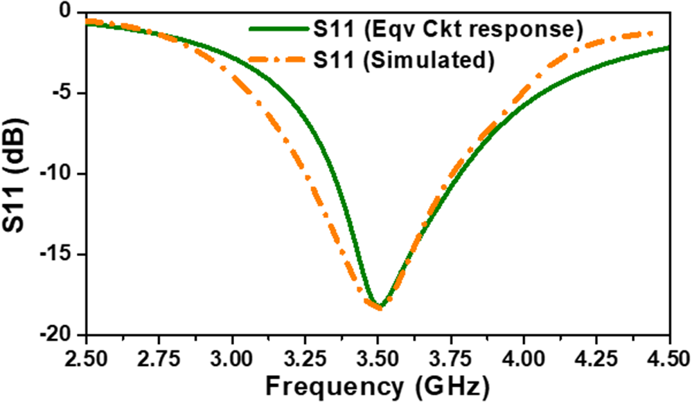
This equivalent circuit can be implemented in circuit simulation tools such as SPICE to predict antenna performance under varying conditions with reasonable accuracy. As shown in Fig. 7, the reflection coefficient response obtained from the equivalent circuit closely matches the result of the full-wave electromagnetic simulation, thereby validating the accuracy and effectiveness of the proposed circuit model.
S11 response of the simulated structure and its equivalent circuit.

Results and discussion
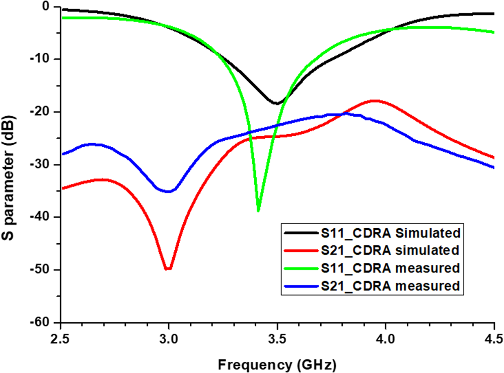
The PCB prototyping machine is used to fabricate the prototype of the CDR-based MIMO antenna, as shown in Fig. 8(a–c). A vector network analyzer was used to measure the proposed CDR-based MIMO antenna S-parameter, whose setup is shown in Fig. 8(d). The radiation characteristics of the proposed MIMO DRA are investigated in an anechoic chamber environment as shown in Fig. 8(e). The simulated and measured reflection and transmission coefficients of the proposed MIMO DRA are shown in Fig. 9. The measured return loss of the proposed CDR-based MIMO antenna is better than 10 dB in the frequency range of 3.2–3.7 GHz, covering the sub-6 GHz band. The isolation of the proposed CDR-based MIMO antenna is better than 20 dB in the operating frequency bands, which satisfies the demand for sub-6 GHz applications.
Images of the suggested MIMO antenna based on CDR. (a) CDR-based MIMO antenna from the top perspective. (b) The CDR-based MIMO antenna's bottom view. (c) The MIMO antenna's top view without the DRA element. (d) Measurement of S parameter. (e) Measurement of Radiation pattern in an echoic chamber environment.

S-parameters of the proposed CDRA-based MIMO antenna.

The measured S-parameters of the proposed CDR-based MIMO antenna demonstrate good agreement with the simulated results, as presented in Fig. 9. The soldering of the connector, surface finishing of the DRA material Eccostock HIK, misalignment or placement errors of the DRA, material inconsistencies, and the thin layer of the glue used to paste the DRA over the substrate are the primary causes of the variation in the simulated and measured S-parameters results of the proposed antenna. However, the operating bandwidth of the proposed CDR-based MIMO antenna is 14.5%. It is highly promising and an attractive choice for the sub-6 GHz band application.
The far field radiation characteristics of the proposed CDR-based MIMO antenna have been thoroughly investigated in an anechoic chamber environment with a corrugated horn antenna as a reference antenna. The other port of the MIMO DRA is matched with a 50 Ω load while measuring the radiation characteristics of the proposed MIMO DRA. The simulated and experimental results are presented in Fig. 10, providing valuable insights into the antenna’s radiation patterns.
The measured result for the co-polarized radiation in the broadside direction closely agrees with the simulated results.
The simulated and measured results both demonstrate a notable difference of about 12 dB between the levels of co-pol and cross-pol in the E plane far field radiation pattern in the broadside direction, as shown in Fig. 10(a). Also better than 10 dB gap is found between the co-pole and cross-pole in the H plane far field radiation pattern in the broadside direction as shown in Fig. 10(b). This meets the accepted standard in antenna technology, indicating excellent polarization purity.
The radiation pattern of the proposed CDR-based MIMO antenna specifically for (a) the E-plane and (b) the H-plane.

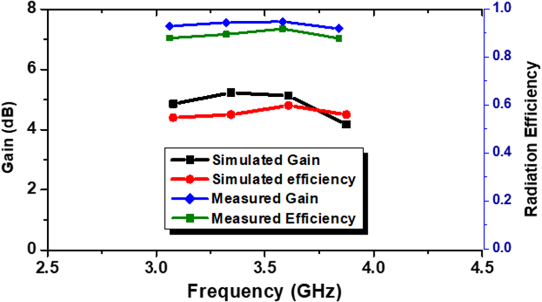
The cause of the cross-polarization is the inherent characteristics of the HEM modes. Figure 11 shows the radiation efficiency and realized gain of the proposed CDR-based MIMO DRA. The proposed MIMO DRA achieves a peak gain of 4.9 dB while maintaining an average gain of 4.7 dB over the operational frequency band, demonstrating its excellent radiation performance. It indicates that the gain of the proposed design is about to be flat in the working band. The radiation efficiency plot shown in Fig. 11 was measured using the same setup as the far-field radiation pattern measurements. A standard gain horn antenna was used as a reference inside an anechoic chamber. The efficiency was calculated by comparing the measured gain of the antenna under test with its simulated directivity, effectively capturing all relevant losses, including dielectric, conductor, and mismatch losses. The close agreement between the measured and simulated results confirms the accuracy of the measured efficiency values. The minimum radiation efficiencies of the proposed CDR-based MIMO DRA are found to be 88% in the operational frequency band. The slight deviation between the simulated and measured results can be attributed to the losses incurred by the connectors, which are of a similar size to the CDR-based MIMO DRA, as well as the influence of the testing cable on the antenna’s radiation characteristics.
Gain and radiation efficiency of the proposed CDR-based MIMO antenna.

Diversity performance
To achieve a significant enhancement in the diversity performance of the MIMO antenna, it is essential to assess the critical diversity performance metrics of the proposed CDR-based MIMO antenna, including the ECC, diversity gain (DG), mean effective gain (MEG), and channel capacity loss (CCL). These parameters play a crucial role in ensuring the reliability and efficiency of the MIMO antenna system. In the multipath environment, there is a close relationship between the angular power spectrum of incident power and the MEG and ECC [Reference Kumar, Ansari, Kanaujia, Kishor and Matekovits28]. Furthermore, ECC is associated with channel capacity. The correlation coefficient (ρ) quantifies the degree of correlation and isolation among distinct channels, illustrating how simultaneous operations in multiport antenna environments influence each other.
The ECC can be calculated using an S-parameter-based equation, as mentioned in [Reference Zou, Abbott and Fumeaux29]. However, this method is only applicable to highly efficient radiators with an efficiency of at least 95%. The ECC for the proposed MIMO antenna is computed using a far-field-based formula [Reference Kumar, Ansari, Kanaujia, Kishor and Matekovits28].
The measured ECC uses the measured amplitude and phase of the far-field electric field. The simulated ECC is plotted using HFSS, which uses simulated far-field electric amplitude and phase.
 \begin{equation} {\rho _{ij}} =
\frac{\begin{array}{c} | \smallint\nolimits^{\Omega }[ \text{XPR}.\text{E}_{\theta i}\text{E}_{\theta j}^{\text{*}}\text{P}_{\theta } \\ + \text{E}_{\theta i}\text{E}_{\theta j}^{\text{*}}P_{\phi} ]d\Omega |^{2}\end{array}}{\begin{array}{c}\smallint \nolimits^{\Omega }[\text{XPR}.\text{E}_{\theta i}\text{E}_{\theta i}^{\text{*}}\text{P}_{\theta } + \text{E}_{\theta i}\text{E}_{\theta j}^{\text{*}}\text{P}_{\phi} ]d\Omega \chi \\ \smallint \nolimits^{\Omega }[ \text{XPR}.\text{E}_{\theta j}\text{E}_{\theta j}^{\text{*}}\text{P}_{\theta } + \text{E}_{\theta j}\text{E}_{\theta j}^{\text{*}}P_{\phi} ] d\Omega \end{array}}
\end{equation}
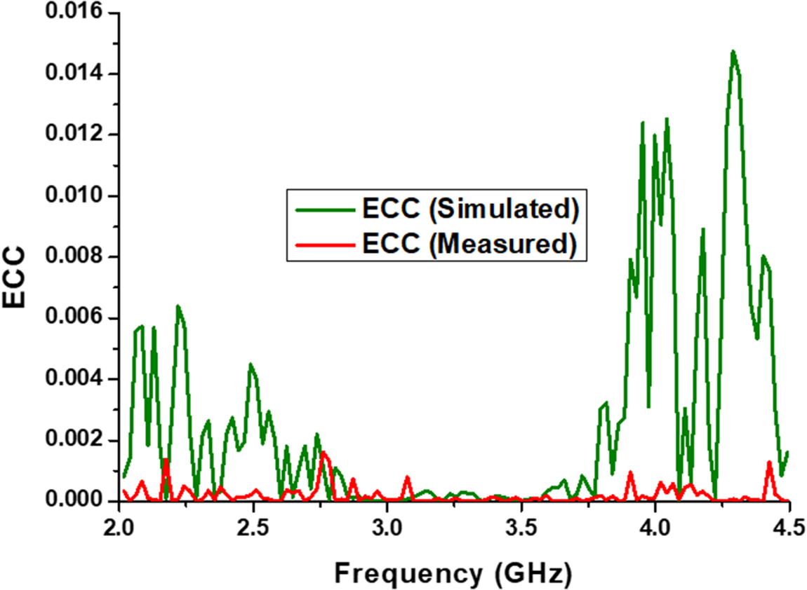
While computing ECC from the far-field equation, a value <0.1 is accepted [Reference Singhwal, Kanaujia, Ajit, Jugul and Matekovits16], unlike 0.05 in the case of ECC from S-parameters. The simulated and measured ECCs are both in good agreement with each other and are less than 0.0015 across the operational bandwidth, as shown in Fig. 12.
Envelope correlation coefficient (ECC) of the proposed CDR-based MIMO antenna.

MIMO antennas have a greater amount of improvement over single-input, single-output antennas, as stated by DG. DG is the ability to focus signal energy in specific directions, enhances signal strength, increases data throughput, and reduces interference.
Ideally, a DG of 10 is desired, although a value above 6 is still considered acceptable [Reference Kumar, Ansari, Kanaujia, Kishor and Matekovits28]. The following formula can be used to determine the DG of a MIMO antenna:
 \begin{equation}{\text{DG}} = 10\sqrt {\left( {1 - {{\left| {{\text{ECC}}} \right|}^2}} \right)} \end{equation}
Interestingly, as it can be calculated from Eq. (6). The proposed CDR-based MIMO antenna achieves a simulated and measured DG of greater than 9.9998 in the entire desired frequency band, which is approximately equal to 10, and this is the major benefit of the proposed antenna. Equation (7) to (11) can be used to compute the proposed antenna’s CCL.
 \begin{equation}{\text{CCL}} = {\text{lo}}{{\text{g}}_2}{\text{det}}(\phi)\end{equation}
where  $\phi = \left[ \begin{array}{cc}
{{\phi _{11}}}&{{\phi _{12}}} \\
{{\phi _{21}}}&{{\phi _{22}}}
\end{array} \right]$
 \begin{equation}\phi_{11} = 1 - \left( {{{\left| {{S_{11}}} \right|}^2} + {{\left| {{S_{12}}} \right|}^2}} \right)\end{equation}
 \begin{equation}\phi_{12} = - \left( {S_{11}^*{S_{12}} + S_{21}^*{S_{22}}} \right)\end{equation}
 \begin{equation}\phi_{21} = - \left( {S_{22}^*{S_{21}} + S_{12}^*{S_{11}}} \right)\end{equation}
 \begin{equation}\phi_{22} = 1 - \left( {{{\left| {{S_{21}}} \right|}^2} + {{\left| {{S_{22}}} \right|}^2}} \right)\end{equation}
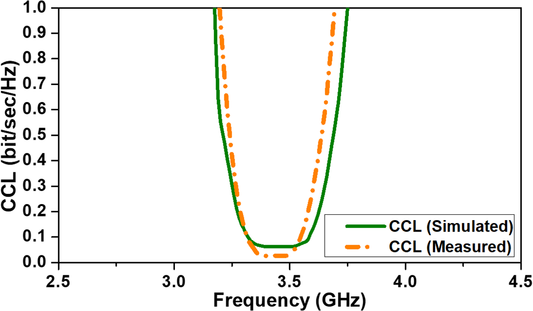
The plot of CCL vs. frequency is displayed in Fig. 13 and was plotted using Eqs. (7), (8), (9), (10), and (11). Channel capacity represents the highest data rate a communication channel can support while maintaining minimal errors. In MIMO systems, it plays a vital role in enabling high data rates and ensuring reliable transmission.
Channel capacity loss of CDR-based MIMO DRA.

The simulated and the measured value of CCL obtained in the desired frequency band are less than 0.5 bit/sec/Hz, which is desired as per industry standards. Interestingly, for the major portion of the desired frequency band required, it is less than 0.1 bit/sec/Hz, which is the main benefit of the proposed MIMO DRA. MEG is the measure of the average gain over all directions. The MEG of the N-port MIMO antenna system is given by Eq. (12) [Reference Mali, Sahu, Suman and Gangwar30].
 \begin{equation}MEGi = 0.5\left[ {1 - \mathop \sum \limits_{j = 1}^N {{\left| {{S_{ij}}} \right|}^2}} \right]\end{equation}
The S-parameters of the proposed CDRA-based MIMO DRA are denoted by Sij, where i ranges from 1 to 2.
A key performance indicator is the difference between the measured embedded gains (MEG1 and MEG2), which should be less than 3 dB for the same input power level. As illustrated in Fig. 14, the proposed MIMO antenna achieves a significant advantage, with the difference between the simulated MEG1 and MEG2 approaching zero while the measured difference remains within 0.5 dB in the operating band.
MEG of CDR-based MIMO DRA.

The difference between the measured MEG1 and MEG2 is less than 0.2 dB, thereby ensuring excellent MIMO DRA performance. The difference between the MEGs is due to the imperfect DRA alignment and placement, imperfect DRA material, and environmental conditions (such as multipath, interference).
Table 3 compares the proposed CDR-based MIMO antenna based on operating frequency (impedance bandwidth), feeding method, and number of ports, realized gain (dBi), isolation (dB), ECC, and dimension of MIMO antenna in terms of λO with the existing literature. It can be observed from column 2 of Table 3 that the IBW of the proposed antenna is the largest among the given literature. The proposed antenna fabrication is simple and easy, as it can be observed from column 3 that there is simple aperture feeding in the proposed MIMO DRA, unlike the complex feed networks in [Reference Bing, Jian, Yu-Xiang, Ying and Yingzeng18], [Reference Jaglan, Gupta, Kanaujia and Sharawi21], [Reference Jaglan, Gupta and Sharawi22], [Reference Zou, Abbott and Fumeaux29]. The realized gain and isolation of the proposed design are comparable to the other literature, as it can be observed from columns 5 and 6 of Table 3. From column 7, it can be observed that ECC is best for the proposed design among all the other literature, which is closely related to channel capacity; hence, the channel capacity is also very good for the proposed design. Column 8 compares the dimensions of the proposed design with the published ones. The volume in terms of λ03 clearly shows that the proposed design has minimum volume except [Reference Jaglan, Gupta, Kanaujia and Sharawi21] and [Reference Jaglan, Gupta and Sharawi22], and hence the proposed design is compact. Here, it is important to note that [Reference Jaglan, Gupta, Kanaujia and Sharawi21] and [Reference Jaglan, Gupta and Sharawi22] are microstrip patch-based massive MIMO antennas and not the MIMO DRAS; their height is mainly due to the height of the substrate. However, it is important to note that [Reference Jaglan, Gupta, Kanaujia and Sharawi21] and [Reference Jaglan, Gupta and Sharawi22] use microstrip patch-based MIMO antennas. Their smaller volume is due to the low substrate height, while their overall area is significantly larger (7.6λ02 and 7.4λ02, respectively) compared to the proposed MIMO DRA (5.4λ02).
Performance comparison with previous MIMO antennas

where λO is the operating wavelength.
Therefore, the proposed CDR-based MIMO antenna offers lower manufacturing complexity, moderate gain, improved insulation characteristics, excellent ECC, and a compact size relative to other published designs.
V. Conclusion
This paper presents the design of a compact MIMO antenna using an aperture-coupled CDRA-based MIMO excited in HEM11δ mode for 5G new radio applications, specifically for sub-6 GHz frequency bands. The designed CDRA-based MIMO antenna boasts a broad impedance bandwidth of 3.2–3.7 GHz, ensuring reliable performance with high data rates and lower latency. Notably, the incorporation of an asymmetric cross slot enables excellent isolation between the CDRA elements, with a minimum isolation of 20 dB within the operational range. Additionally, the antenna achieves a decent gain of 4.7 dB. The proposed CDR-based MIMO antenna improved ECC values because of the low field correlation. Furthermore, the proposed MIMO antenna’s diversity performance is thoroughly evaluated, with a focus on DG and TARC of the channel. Given its remarkable characteristics, the proposed antenna is an optimal solution for sub-6 GHz applications, as it enables the achievement of high data rates and low latency, making it well-suited for 5G use cases.
Data availability statement
No new data were created or analyzed in this study.
Acknowledgements
The authors acknowledge the Department of Electronics and Communication Engineering, National Institute of Technology, for their instrumental support for this study.
Competing interests
The authors report no conflict of interest.

Manoj Kumar Vishwakarma is currently a Ph.D. scholar in the Department of Electronics and Communication Engineering at the National Institute of Technology (NIT), Patna, India. He earned his Master’s degree in Electronics and Communication Engineering with a specialization in Microwave Engineering from Birla Institute of Technology, Mesra, Ranchi, in 2011. He is presently serving as an Assistant Professor in the Department of Electronics and Communication Engineering at LLOYD Institute of Engineering and Technology, Greater Noida, India. With more than a decade of academic and research experience, his work focuses on radio frequency (RF) and microwave engineering, antenna design, and microwave components. He has designed and analyzed various microstrip patch antennas, substrate integrated waveguide (SIW) band pass filters, and multi-input multi-output (MIMO) dielectric resonator antennas (DRAs). Most of his antenna and filter designs are modeled and validated using advanced electromagnetic simulation tools such as Ansys HFSS. His current research emphasizes compact, high-performance antenna systems for 5G and sub-6 GHz applications, with a particular interest in MIMO DRA configurations. His broader research interests include microwave filters, SIW technology, and MIMO Technology. He is actively engaged in publishing his research contributions in reputed journals and conferences.

Jugul Kishor is a Professor in the Department of Electronics and Telecommunication Engineering at Dayananda Sagar College of Engineering, Bengaluru, Karnataka, India. He earned his B. Tech in Electronics Engineering from Kamla Nehru Institute of Technology, Sultanpur, in 2002, his M. Tech in Microwave Electronics from the University of Delhi in 2008, and his Ph.D. from the Indian Institute of Technology (Indian School of Mines), Dhanbad, Jharkhand, in 2017. He has published over 50 papers in various JCR journals and conferences, with citations and an h-index. He reviews many peer-reviewed journals and conferences, such as IEEE Access, IEEE Transactions on Antennas and Propagation, Journal of Electronics, AEU-International Journal of Electronics and Communications, International Journal of RF and Microwave Computer-Aided Engineering, Microwave Optical Technology and Letters, and IEEE Transactions on Circuits and Systems. He is a member of professional organizations including IEEE MTT-S and URSI. During his Ph.D., he designed and characterized dielectric resonator-based band-pass filters. His research interests include designing and modeling microstrip- and dielectric resonator-based devices, as well as metamaterial-inspired antennas, such as circularly polarized antennas and MIMO antennas.

Jayanta Ghosh received the M.E. and Ph.D. degrees in electronics and communication engineering from the Birla Institute of Technology, Mesra, India, in 2005 and 2012, respectively. He is currently an Associate Professor with the Department of Electronics and Communication Engineering, National Institute of Technology Patna, India. His research interests include antennas, artificial materials and MICs. He is a Senior member of IEEE and a Member of IE(I). He is a reviewer of several journals of international repute. ORCID ID: 0000-0002-1321-5380.