Introduction
The rising prevalence of in situ techniques in transmission electron microscopy (TEM) highlights an important fact: Conventional microscopy on static samples captures only what the sample is (structure) and not what it does (dynamics). Modern applications, ranging from materials science to biology to nanotechnology, demand an understanding of microscale and nanoscale dynamics, and in situ TEM fills this need by revealing not just the start and end states of a process, but also the states in between. Such information is crucial for the development and testing of models for mesoscale (∼1 nm to ∼10 μm) dynamics and predictive capabilities for designing nanotechnological systems. Yet, many in situ TEM instruments are limited to conventional video frame rates (∼33 ms), often far too slow to catch the relevant dynamics. At such frame rates, 10 nm of motion blur corresponds to a feature moving at only ∼0.3 μm/s, an exceptionally slow speed compared to many dynamical processes such as microstructural evolution in phase transformation fronts, with characteristic speeds of some millimeters or meters per second.Reference Porter and Easterling1 Capturing such processes requires nanosecond-scale resolution. Many studies on condensed-matter physics require even higher time resolutions, at the picosecond level or lower.
These needs motivate today’s efforts to improve TEM time resolution by orders of magnitude through dynamic and ultrafast TEM (DTEM and UTEM, respectively). DTEM and UTEM, along with femtosecond lasers, free-electron x-ray lasers, high harmonic generation, and ultrafast electron diffraction, are part of an ongoing revolution in high-time-resolution studies in chemistry, materials science, biology, atomic physics, and condensed-matter physics. Although all of these fields benefit from recent developments in lasers, electron sources, and electronics, they also share a long history, with roots going back many decades, and time-resolved electron microscopy is no exception. In the mid-1960s, Spivak et al. developed a multishot accumulation (i.e., stroboscopic) system to study magnetic domain wall motion, achieving microsecond time resolution by gating the thermionic electron source in a scanning electron microscope.Reference Spivak, Pavlyuchenko and Petrov2 Enabled by the development of pulsed lasers in the 1970s, Bostanjoglo and co-workers improved the temporal resolution of in situ TEM observations to nanosecond time scales using pulsed lasers to generate short electron bunches through thermal emission and later by UV-stimulated photoemission.Reference Bostanjoglo3–Reference Domer and Bostanjoglo6 Bostanjoglo and Domer especially focused on the single-shot approach in which a single pulse contains enough electrons to form a complete image.Reference Domer and Bostanjoglo6 More recently, Zewail and co-workers pushed the temporal resolution of the stroboscopic approach to the subpicosecond regime using femtosecond lasers,Reference Barwick, Park, Kwon, Baskin and Zewail7–Reference Zewail9 and researchers at Lawrence Livermore National Laboratory (LLNL) advanced the single-shot technique through the development of DTEM, which uses a single, intense electron pulse to image transient material states with nanometer/nanosecond resolution.Reference Armstrong, Boyden, Browning, Campbell, Colvin, DeHope, Frank, Gibson, Hartemann, Kim, King, LaGrange, Pyke, Reed, Shuttlesworth, Stuart and Torralva10–Reference Reed, Armstrong, Browning, Campbell, Evans, LaGrange and Masiel15
The single-shot and stroboscopic approaches to high-time-resolution in situ TEM are complementary, based on similar physical principles but in very different regimes, and each is optimized for its own broad class of experimental problems. If the process to be studied occurs through a series of unique and irreversible events, as is typical of microstructural evolution and many solid-state phase transformations and chemical reactions, then a single-shot approach is required to observe the dynamics.Reference LaGrange, Campbell, Reed, Taheri, Pesavento, Kim and Browning13,Reference LaGrange, Reed, Santala, McKeown, Kulovits, Wiezorek, Nikolova, Rosei, Siwick and Campbell14,Reference Campbell, LaGrange, Kim, Reed and Browning16–Reference Taheri, LaGrange, Reed, Armstrong, Campbell, DeHope, Kim, King, Masiel and Browning23 The spatial and temporal resolution of this technique is limited to the nanometer and nanosecond scales by electron–electron interactions and the brightness of the electron source.Reference Armstrong, Boyden, Browning, Campbell, Colvin, DeHope, Frank, Gibson, Hartemann, Kim, King, LaGrange, Pyke, Reed, Shuttlesworth, Stuart and Torralva10–Reference Reed, Armstrong, Browning, Campbell, Evans, LaGrange and Masiel15
The stroboscopic approach reaches subpicosecond time scales by accumulating the signals from millions of nominally identical laser-pump/electron-probe experiments from the same region on the sample, thus, requiring highly repeatable processes that return to the undisturbed state between pump–probe cycles.Reference Barwick, Park, Kwon, Baskin and Zewail7,Reference Zewail9,Reference Lobastov, Srinivasan and Zewail24 Repeating the experiment for a series of pump–probe time delays yields a movie of an average cycle of the process. The stroboscopic approach is appropriate for the study of electronic excitations; elastic deformation; magnetic material dynamics; and other highly repeatable, reversible solid-state phenomena.Reference Barwick, Flannigan and Zewail25–Reference Kwon, Barwick, Park, Baskin and Zewail31
For high performance, the single-shot approach requires modification of the TEM column to handle the extraordinarily high currents (multiple milliamperes, compared to the nanoamperes of conventional TEM),Reference LaGrange, Campbell, Reed, Taheri, Pesavento, Kim and Browning13,Reference LaGrange, Reed, Santala, McKeown, Kulovits, Wiezorek, Nikolova, Rosei, Siwick and Campbell14,Reference Reed, LaGrange, Shuttlesworth, Gibson, Campbell and Browning32 whereas the stroboscopic approach typically uses the standard electron optics and configurations of the TEM manufacturer. In both cases, high time resolution requires that the electron source be based on laser-driven photoemission and that the TEM instrument be modified to provide laser access to the electron source and the sample. Although some other mechanisms have been proposed,Reference Krüger, Schenk and Hommelhoff33 laser-based photoemission is the only proven way to generate pulses with the brightness and short durations needed for high-time-resolution electron microscopy.Reference Armstrong, Reed, Torralva and Browning11,Reference LaGrange, Armstrong, Boyden, Brown, Campbell, Colvin, DeHope, Frank, Gibson, Hartemann, Kim, King, Pyke, Reed, Shirk, Shuttlesworth, Stuart, Torralva and Browning12,Reference Reed, Armstrong, Browning, Campbell, Evans, LaGrange and Masiel15,Reference King, Campbell, Frank, Reed, Schmerge, Siwick, Stuart and Weber34
Movie-mode DTEM
Movie-mode DTEM (MM-DTEM, Figure 1) refers to a technique in which multiple single-shot acquisitions are captured in as little as ∼1 μs, producing a frame rate nearly 106 times higher than that obtained by conventional in situ TEM. MM-DTEM is designed for studying processes in which complex sequences of irreversible events unfold in just a few microseconds. Although similar capabilities were developed in the past,Reference Bostanjoglo and Rosin35–Reference Takaoka and Ura37 modern MM-DTEM works by using a laser based on an arbitrary waveform generator (AWG) to generate a series of electron pulses and a fast post-sample deflector to send each pulse to a different region on a camera.
Schematic of movie-mode dynamic transmission electron microscope. (1) An arbitrary-waveform laser strikes a photocathode, producing a series of (2) nanosecond to microsecond scale electron pulses with any desired temporal pattern. (3) A second laser strikes the sample, initiating the process to be studied. (4) A high-speed deflector (also broken out in detail on the right-hand side) deflects each of the nine images onto (5) a camera, allowing the system as a whole to capture multiple images in a single microsecond. Note: AWG, arbitrary waveform generator; CCD, charge-coupled device. Figure created by Ryan Chen of the Technical Information Department at Lawrence Livermore National Laboratory.

Modified electron optics
First, we discuss the electron optical issues associated with single-shot and MM-DTEM, as well as methods for addressing these issues. Given the need to capture a complete high-quality image, which requires ∼108–1010 electrons in ∼10 ns, DTEM must use beam currents of tens or hundreds of milliamperes. These values are orders of magnitude greater than the currents used in conventional TEM, forcing some changes to the gun and condenser lens systems. Conventional TEM typically discards most of the beam current to improve spatial coherence, but DTEM can afford no such luxury. Optimal performance at multi-milliampere currents requires modifications, including (1) removal of many of the fixed apertures, especially those between the gun and the first condenser lens (C1); (2) replacement of the sharp cathode tip with a flat cathode designed for uniform emission over a large (∼100-μm) region with uniform extraction fields and low geometrical aberrations; and (3) modification of the condenser lens system itself, for example through the addition of a weak “C0 lens” (called so because it precedes the C1 lens), as described in Reference 32.
With these modifications, a large fraction of the electrons that leave the cathode can be directed onto a few-micrometer-diameter region on the sample, with negligible degradation of effective brightness from condenser lens aberrations. High gun-to-sample throughput is crucial. Because current extraction from a DTEM photocathode is always in the space-charge-limited regime, such that the electric field from recently emitted electrons retards and deflects later electrons, any electron emitted but not used represents an irretrievable loss in performance.
The use of large sources and apertures implies a reduction in spatial coherence at the sample. This is an inevitable consequence of the law of conservation of brightness and the extremely high current. As a result, single-shot DTEM images cannot be expected to reach subnanometer resolution unless either (1) the exposure time is increased to the microsecond regime, or (2) the brightness of the gun is greatly improved.Reference Reed, Armstrong, Browning, Campbell, Evans, LaGrange and Masiel15 Even if the gun brightness is increased, the ultimate resolution limit might come not from limited spatial coherence but rather from electron–electron scattering in post-sample crossovers.Reference Armstrong, Reed, Torralva and Browning11 This “stochastic blur” effect can be reduced by increasing the electron kinetic energy to the megaelectronvolt regime, but this carries complications, including engineering challenges and sample damage.
Movie-mode laser system
The generation of a laser pulse train enables MM-DTEM to yield a series of time-resolved nanosecond images of a transient materials event. The AWG laser provides unique flexibility for tailoring the laser parameters for a given experiment. This laser can shape laser pulses in any desired temporal pattern, thus allowing the experimenter to easily change the pulse duration, arrival time, and intensity for every single pulse. The AWG uses a high-speed digital-to-analog convertor to drive a fiber-based electro-optical modulator, thereby temporally shaping a continuous-wave fiber-laser seed pulse. The modulated waveforms are then amplified through fiber and neodymium:yttrium aluminum garnet rod amplifiers, frequency-converted to ultraviolet, and delivered to the instrument’s photocathode. The result is a train of electron pulses, each pulse with a specified duration ranging from 10 ns to 1 μs, distributed in any desired pattern within a 100-μs window. The AWG also allows each pulse to be shaped such that after the multiple nonlinear processes between the modulator and the cathode, each electron pulse has a square temporal profile, thus avoiding effective brightness degradation from time-varying space charge effects.
High-speed deflector system
There are two ways to separate the individual images produced by each electron pulse in the train. One is to use a fast framing camera to capture each image between pulses. This would require a highly specialized camera with performance specifications challenging the limits of current technology. The other option is to install a high-speed deflector (Figure 1, detail on right-hand side) system between the sample and a standard TEM camera so as to deflect each pulse onto a different area of the camera, with an electronic timing system that switches deflection states in the dead time between electron pulses. This is the method used in the LLNL MM-DTEM prototype.Reference LaGrange, Reed, Santala, McKeown, Kulovits, Wiezorek, Nikolova, Rosei, Siwick and Campbell14,Reference Santala, Reed, Raoux, Topuria, LaGrange and Campbell38
Because MM-DTEM demands interframe times of tens to hundreds of nanoseconds, the deflector uses electrostatic plates (following the pioneering work in References 3, 4, and 6) rather than magnetic coils. Various designs are possible, for example, a single-stage multipole unit or (as in the LLNL prototype) two perpendicular pairs of nearly parallel plates. Because the cost and engineering difficulties of high-speed switching electronics scale rapidly with the voltage, the plates need to be designed to operate with as low a voltage as possible while keeping specifications for image distortion and field of view within acceptable tolerances. The LLNL prototype operates at 850 V, with interframe times of ∼75 ns (limited by residual blur as the voltage settles to its final value) and independent control over all four deflectors. Using different voltages for different deflector plates, this system can collect up to 16 frames in a single acquisition.
Example applications of movie mode: Phase evolution in reactive nanolaminate foils
An example is presented of the benefits of MM-DTEM for a specific case—chemical reaction propagation fronts in reactive multilayer foils (RMLFs). These foils consist of alternating layers of dissimilar metals and are used for rapid, local application of heat for joining and fusing applications. Before movie mode became available, DTEM experiments were limited to a single image frame per sample drive event, which, in the case of RMLFs (in which each event consumes an entire film), meant that a fresh sample was needed for every time delay to be captured. Although this approach has provided a general view of the microstructural evolution in Ni-Al RMLFs (including the revelation of an unexpected emergent liquid-phase structureReference Kim, LaGrange, Reed, Knepper, Weihs, Browning and Campbell17,Reference Kim, LaGrange, Reed, Taheri, Armstrong, King, Browning and Campbell18 ), it cannot reveal in detail how individual microstructural elements evolve, nor can it fully quantify the inherent variability of the process. This variability means that the arrival time of the reaction front at a given point has an inevitable random error, and in the case of RMLFs, this error is comparable to the time scale of the reaction itself. This means that precise extraction of reaction rates, kinetic parameters, and statistical distributions of propagation rates in single-shot DTEM can be quite tedious; indeed, a great many samples and many days of experiment time are required to bring the error bars under control.
MM-DTEM solves this problem by capturing multiple images as a single reaction front passes through the field of view (Figure 1). A single measurement of one sample produces a data set with statistical power rivaling a week’s effort using the single-frame approach. Not only can the front velocity be measured with high precision, but its statistical variation can also be measured in space and time, allowing assessment of the mechanisms that produce propagation instabilities. Such understanding is crucial for developing and optimizing RMLFs for specific applications, and it also opens a unique window onto far-from-equilibrium material dynamics.
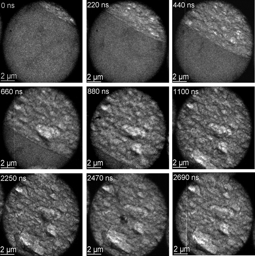
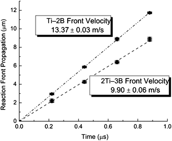
The example in Figure 2 shows the MM-DTEM acquisition of a reaction front in a Ti–B RMLF with the stoichiometry 2Ti–3B.Reference LaGrange, Reed, McKeown, Santala, Dehope, Huete, Shuttlesworth and Campbell39 The granulated appearance of the product phases provides a stark contrast between the reacted and unreacted zones, allowing precise determination of the front velocity: 9.90 ± 0.06 m/s. A similar measurement of an RMLF with the stoichiometry Ti–2B revealed a higher velocity of 13.37 ± 0.03 m/s (see Figure 3), as expected from the higher reaction heat and resulting higher temperatures as well as the enhanced diffusion kinetics and reaction rates.Reference LaGrange, Reed, McKeown, Santala, Dehope, Huete, Shuttlesworth and Campbell39 In both cases, the propagation speed was constant, which, along with the smooth appearance of the front, indicates a stable, steady propagation regime. Surprisingly, the product-phase microstructure formed quickly behind the front and, once formed, exhibited neither coarsening nor morphological changes. Close examination revealed a thin (100–200-nm) dark-contrast region at the reaction front, which we speculate to be liquid. A short-lived liquid phase is expected, as Ti–B reactions have high combustion enthalpies of 4200 kJ mol–1 and adiabatic temperatures of 3200 K that far exceed the melting temperatures of titanium, boron, and some of their compounds but are lower than the melting point of TiB2;Reference Li40 under this interpretation, the thickness of the dark-contrast line is related to the time required for full intermixing and formation of the final product. This is in contrast to the much longer-lived and morphologically distinct liquid-phase striations observed in previous DTEM measurements of Ni–Al RMLFs,Reference Kim, LaGrange, Reed, Knepper, Weihs, Browning and Campbell17,Reference Kim, LaGrange, Reed, Taheri, Armstrong, King, Browning and Campbell18 indicating very different transformation pathways for the two material systems.
Nine-image sequence of a propagating front in a reacting 2Ti–3B reactive nanolaminate film. The exposure time of each image was 17 ns. Note the thin dark line at the reaction front, which we interpret as a short-lived and likely inhomogeneous liquid phase with enhanced thermal diffuse scattering.Reference LaGrange, Reed, McKeown, Santala, Dehope, Huete, Shuttlesworth and Campbell39
Plot of the measured reaction front propagation as a function of time for Ti–2B and 2Ti–3B films. The results show that the speed can be precisely determined using a movie-mode dynamic transmission electron microscope and that the speed is constant for a given film, yet can be varied by changing the film composition.Reference LaGrange, Reed, McKeown, Santala, Dehope, Huete, Shuttlesworth and Campbell39
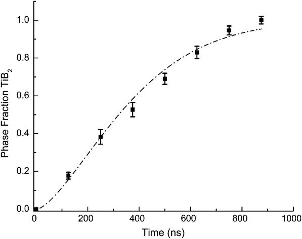
To characterize the phase evolution under steady-state reaction conditions, we obtained a sequence of diffraction patterns using MM-DTEM as the reaction front passed through a 1.75-µm-diameter field of view in a Ti–B system (shown in Figure 4).Reference LaGrange, Reed, McKeown, Santala, Dehope, Huete, Shuttlesworth and Campbell39 At the reaction front (0 ns), the diffraction pattern exhibits three broad peaks with peak positions and intensities that cannot be attributed to nanocrystalline β-Ti or boron. The measured peaks were much broader and shifted to higher scattering vectors with time, indicative of a disordered noncrystalline phase, consistent with a liquid phase existing at the front. A significant fraction of TiB2 formed within 250 ns, and the foil completely transformed within 750 ns. Given the front velocity, a transient zone existing for 750 ns corresponds to a distance beyond the front of 7.5 µm, illustrated by the scaled real-space image adjacent to the diffraction spectra in Figure 4. At times less than 250 ns, we observed irregular dark regions in the real-space images that were speculated to be pockets of liquid, and this is consistent with the broad diffraction peaks observed from 0 to 125 ns.
Sequence of diffraction spectra collected by movie-mode dynamic transmission electron microscopy as a reaction front passed through a 1.75-µm-diameter field of view, showing the evolution from an amorphous Ti–B structure to a nanocrystalline (nc) TiB2 hexagonal crystal structure. The simulated electron diffraction patterns were calculated assuming an effective instrumental broadening and 50-nm grain size and allow identification of the phases present at various times as the reaction proceeds, for example through the appearance and disappearance of peaks characteristic of TiB (blue dashed lines) and TiB2 (red dashed lines). The micrograph of a snapshot of the propagating front shows the position in the front corresponding to each point in time.Reference LaGrange, Reed, McKeown, Santala, Dehope, Huete, Shuttlesworth and Campbell39
The kinetics of the transformation to the TiB2 phase can be quantified by assuming the overall diffraction spectra to be superpositions of the individual spectra of nanocrystalline TiB2 and an amorphous Ti–B phase and using Rietveld analysis to determine the TiB2 phase fraction f as a function of time (Figure 5).Reference LaGrange, Reed, McKeown, Santala, Dehope, Huete, Shuttlesworth and Campbell39 We employed Johnson–Mehl–Avrami–Kolmogorov analysis to obtain the kinetic parameter K, the incubation time τ, and the Avrami dimensionality parameter n as defined in the equation:Reference Avrami41,Reference Johnson and Mehl42
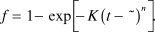 $$f = 1 - \exp \left[ { - K{{\left( {t - {\rm{\tau }}} \right)}^n}} \right].$$
Phase fraction f of TiB2 as a function of time determined through Rietveld refinement analysis of diffraction patterns in Figure 4.Reference Santala, Reed, Raoux, Topuria, LaGrange and Campbell38 These data were fit with the Johnson–Mehl–Avrami–Kolmogorov analytical model (see Equation 1) to determine the activation barrier E, incubation time τ, and dimensionality n of the reaction. Note: K, kinetic parameter; K 0, kinetic parameter prefactor; T c, combustion temperature; κ, Boltzmann’s constant.Reference LaGrange, Reed, McKeown, Santala, Dehope, Huete, Shuttlesworth and Campbell39
The resulting value of the Avrami parameter, n = 1.5, indicates heterogeneous nucleation with one-dimensional growth, as expected for a steady-state propagating planar reaction front. The large, 13-ns error in the 2-ns incubation time suggests that product-phase nucleation has no incubation or that products readily nucleate at the front. Assuming an Arrhenius relationship with temperature, the activation energy E can be calculated from the expression
 $$K = {K_0}\exp \left( { - E/{\rm{\kappa }}{T_{\rm{c}}}} \right),$$
with Boltzmann constant κ and combustion temperature T c. Using a kinetic parameter prefactor K 0 = 4 × 10¹⁰ s–1 from Reference 39, the activation energy is calculated to be 439 ± 11 kJ mol–1, comparable to published values determined from combustion-wave speed analysis of Ti–2B powder compacts.Reference Azatyan, Maltsev, Merzhanov and Seleznev43,Reference Holt, Kingman and Bianchini44 Holt et al. measured an activation barrier to form TiB2 of 539 kJ mol–1 and a lower barrier of 410 kJ mol–1 for the mixed reaction of Ti + 1.5B, producing both TiB and TiB2.Reference Holt, Kingman and Bianchini44 Although the latter activation barrier is quite close to our result, we did not observe the TiB product phase. This might be because of the rapid evaporation of the Ti capping layers (>8 at.% in Ti, determined by post-mortem energy-dispersive x-ray spectroscopy), cooling the foil in excess of 108 K/s and altering the kinetic pathway to produce only the TiB2 product phase.
This example shows the ability of MM-DTEM to produce detailed quantitative information about complex nonequilibrium nanoscale phenomena. The image series in Figure 2 and the set of diffraction patterns in Figure 4 came from just two MM-DTEM acquisitions, compared to many days of sample preparation and experiment time that would have been required for single-exposure DTEM. Moreover, the MM-DTEM data are of sufficient quality to allow extraction of precise kinetic parameters that compare well with expected values and those reported in the literature. In addition, important observations such as the lack of microstructural coarsening after the reaction and the steady propagation speed simply could not have been performed with single-pump/single-probe DTEM. Movie mode enables entirely unprecedented kinds of measurements, finally allowing the direct observation of fast, complex material processes that have, until now, been only dimly glimpsed.
The future of movie-mode DTEM instrumentation
Ultimately, we expect the temporal regimes of stroboscopic UTEM, DTEM, and conventional in situ TEM to overlap into a continuum. UTEM achieves subpicosecond time resolution by accumulating signal over millions of process cycles, but as the time resolution is relaxed, so is the number of required pulses per image, eventually reaching one pulse per image in the DTEM regime. With current technology, this crossover occurs at roughly 10 ns, depending on the required signal-to-noise ratio. Future megavolt DTEM instruments with ultrabright electron sources might push this transition to 1 ns or below.Reference Armstrong, Reed, Torralva and Browning11 Electron kinetic energies in the MeV (or few MeV) range are required to mitigate stochastic blur effects in post-sample crossovers, although other strategies such as annular dark-field imaging or astigmatic crossovers in multipole imaging systems have also been proposed.
However, this only solves one of the resolution bottlenecks, the other being finite brightness. TEM-like imaging of microstructure (e.g., diffraction-contrast imaging of dislocations and grain boundaries) requires some spatial coherence of the electron beam as it reaches the sample. Experience with the LLNL DTEM instrument suggests that the image quality becomes acceptable when the coherent fluence (N C, the number of electrons per transverse coherence area per pulseReference Reed, Armstrong, Browning, Campbell, Evans, LaGrange and Masiel15) is ∼1. This threshold depends on the contrast mechanism. Extremely incoherent imaging modes (e.g., shadow imaging of very thick material) can suffice with much less coherent fluence, whereas phase-contrast atomic-resolution imaging will require much more. The problem is that for a fixed normalized peak brightness B N, N C is directly proportional to the pulse duration. B N itself is a function of the cathode material, the extraction field, and the physics of photoemission and cannot be improved with lenses, accelerators, apertures, or aberration correctors. Current megavolt-/picosecond-scale electron pulse sources usually have coherent fluences of much less than 1, which means that their use in single-shot imaging systems might be limited to the most incoherent contrast mechanisms. Details of microstructure, not to mention atomic-scale structure, might require substantial increases in source brightness, perhaps through unconventional electron sources such as the emerging ultracold gas sources.Reference Claessens, van der Geer, Taban, Vredenbregt and Luiten45,Reference McCulloch, Sheludko, Saliba, Bell, Junker, Nugent and Scholten46
Continuing an upward path through the continuum of time scales, one reaches the scale of tens of nanoseconds, where not just single shot but also MM-DTEM becomes possible, with multiple images per sample event. This technology is still in its early days, and one can expect not only decreases in the minimum interframe time (currently ∼75 ns), but also increases in the maximum movie duration (currently ∼100 μs with up to 16 frames). This leaves a gap between MM-DTEM and conventional in situ TEM, with its continuous rolling acquisition and millisecond-scale interframe times. Ultimately, MM-DTEM should also be developed into a rolling-acquisition system, possibly by combining the fast deflectors with a direct-detection framing camera operating at hundreds of kilohertz, such that nanosecond-scale measurements can be conducted with almost no limit on the total frame count of a movie.Reference King, Campbell, Frank, Reed, Schmerge, Siwick, Stuart and Weber34 This possibility carries significant engineering challenges. The acquisition system must have extremely high data throughput and capacious storage, and the power and heat-dissipation requirements will be very challenging for the arbitrary-waveform-photocathode approach used in the LLNL dynamic transmission electron microscope.
Conclusions
With the ongoing development of MM-DTEM and UTEM, in situ TEM is moving toward a truly general capability for observing complex atomic-, nano-, and microscale materials phenomena on their own natural time and length scales and under the same physical conditions as used in real-world applications. Our example of Ti-B reactive multilayer foils shows how MM-DTEM can produce both quantitative insights and qualitative data for a deep and complete understanding of a real-world far-from-equilibrium materials problem under the same extreme temperatures and temperature gradients as encountered in the application. Previous examplesReference Santala, Reed, Raoux, Topuria, LaGrange and Campbell38 showed how MM-DTEM can reveal the details of crystalline nucleation and growth in thin-film phase-change memory materials at the actual ∼900 K temperatures of the application, and extrapolation of previously available low-temperature data to 900 K was practically useless for determining relevant kinetic parameters. MM-DTEM, in particular, excels at revealing not just the average statistical behavior of a process, but also deviations from the average, and in many applications, it is the variability that ultimately determines the reliability of the phenomenon for technological applications. The observed steady nature of the Ti–B reaction front, for example, is important for its ability to perform in its intended use, namely, rapidly and reliably depositing a large amount of heat into a small volume. Despite rapid development over the past decade, UTEM and DTEM have substantial room for improvement, including incorporation of ultrabright electron sources, extension of the technology to higher beam voltages, and gradual merging and overlapping of the temporal domains of UTEM, DTEM, and conventional in situ TEM, thus, finally and completely opening up the black box of nanoscale materials dynamics.
Acknowledgments
MM-DTEM research on reactive multilayer foils was supported by the US Department of Energy (DOE), Office of Science, Basic Energy Sciences (BES), under field work proposal SCW0979, and the work conducted at Lawrence Livermore National Laboratory (LLNL) was performed under the auspices of the DOE by Lawrence Livermore National Laboratory under Contract DE-AC52-07NA27344. We acknowledge David Adams and Robert Reeves of Sandia National Laboratories (Albuquerque, NM) for producing the Ti-B RMFLs used in the MM-DTEM studies presented in this article and for fruitful discussions regarding the dynamics of RMLFs. We also acknowledge Ryan Chen of the Technical Information Department of LLNL for the production of the MM-DTEM graphic shown in Figure 1.