Introduction
The recent tremendous development of smart technology leads to the massive requirement of wearable devices in the field of biomedical applications [Reference Sun, Cheung and Yuk1, Reference Kang, Wu and Tarng2]. The sensors utilized in this device wirelessly monitor the important parameters of patients, firefighters, military personnel, such as ECG, blood pressure, Temperature, pH, sweat, body posture, movements, etc. [Reference Zheng, Zhang, Chen and Yan3]. Antennas play a vital role in the smart sensor devices for information processing and further communication to external devices. Such smart wireless devices magnificently require the integrated antenna to possess the characteristics such as compact, low profile, lightweight, and easily portable [Reference Prudhvi Nadh, Madhav, Siva Kumar, Venkateswara Rao and Anilkumar4]. To improve flexibility, most of the wearable antenna designs are fabricated on a flexible substrate such as Kapton polyimide [Reference Bahrami, Mirbozorgi, Ameli, Rusch and Gosselin5], textile [Reference Sun, Cheung and Yuk1], and paper, etc. For providing the small footprint, a folded antenna [Reference Kang, Wu and Tarng2] using a bevel-edge feed structure and a metal plate with the folded strip are reported for WBAN application but it results in the increased vertical height. On the other hand, when wearable antennas are incorporated in/around human bodies, the emitted power should be maintained below a certain mask. UWB technology becomes an active solution for WBAN applications because of its high bandwidth communication along with its low power consumption [Reference Bahrami, Mirbozorgi, Ameli, Rusch and Gosselin5, Reference Shaker, Safavi-Naeini, Sangary and Tentzeris6], robustness against multipath [Reference Koohestani, Zürcher, Moreira and Skrivervik7], and provides scalable data rate over short distances [Reference Hammache, Messai, Messaoudene and Denidni8]. Low power spectral density leads to the increased longevity of the battery life and also reduces the electromagnetic exposure of on-body devices suitable for body-worn wireless communication [Reference Yan, Soh and Vandenbosch9]. Apart from this, the antenna should be designed with the required radiation characteristics suitable for different service environments [Reference Khaleel10].
To enhance the communication between body-worn devices such as wristband and smart glass devices, monopole-like radiation characteristics is required for on-body communication [Reference Jeong, Tak and Choi11]. The performance degradation such as impedance mismatch, frequency detuning, reduced gain, and efficiency occurs due to the high permittivity and conductivity of the human tissues. To overcome the reduced gain and efficiency and to achieve the monopole-like radiation characteristics, the antenna with vertical polarization is illustrated [Reference Yang, Hu and Liu12] with increased vertical height. This results in the obstruction of human comfort in day-to-day activities. The radiation pattern in the compact planar UWB [Reference Doddipalli and Kothari13] is slightly degraded at higher frequencies due to the effect of increased harmonics. Therefore, the omnidirectional radiation pattern along the azimuth plane in a low-profile antenna is the most common requirement for WBAN application. Another requirement is to interface the communication between the body-worn devices to the external devices, directional radiation is preferably suitable for off-body communication. A low profile linear polarized UWB conformal antenna [Reference Balderas, Reyna, Panduro, Del Rio and Gutiérrez14] with a size of 29 × 39 mm for UAV application is reported. A slot antenna backed with a reflector [Reference Klemm, Kovcs, Pedersen and Troster15] achieves the lower UWB frequency range of 3–6 GHz with a directional radiation pattern but the spacing between the antenna and the reflector is 6 mm. A flexible directional antenna on a PDMS substrate is discussed in [Reference Simorangkir, Kiourti and Esselle16] for the UWB frequency range of 3.7–10.3 GHz but it contains a large antenna dimension. All the existing design producing a directional radiation pattern holds a large antenna dimension [Reference Klemm, Kovcs, Pedersen and Troster15–Reference Padmathilagam, Malathi, Shini, Rajesh, Gulam Nabi Alsath, Shanmathi, Sindhadevi and Sandeep Kumar17]. Thus, the design of an antenna with a directional radiation pattern for the entire UWB frequency range in a compact microstrip patch antenna is a challenging task.
Multipath fading occurs due to the movement of body parts, shadowing, scattering, and also from the external environment [Reference Joo, Kwon and Choi18]. This can be mitigated using an integration of multiple input multiple output (MIMO) techniques with the UWB antenna. Spatial multiplexing in MIMO systems increases data throughput and also reduces the multipath fading using a diversity scheme [Reference Toktas and Akdagli19]. This combination provides a high data rate, channel capacity and also increases the received signal strength by constructively adding the signal from different antennas. MIMO antennas should be configured in a compact package to reduce space consumption but it results in the increased coupling between the antenna elements [Reference Chandel, Gautam and Rambabu20]. The omnidirectional radiation pattern [Reference Chandel, Gautam and Rambabu20–Reference Mathur and Dwari24] obtained causes radiation exposure when tested on body tissues. From the aforementioned literature, the issues found are as follows: large antenna dimension [Reference Sun, Cheung and Yuk1–Reference Kumar Biswas and Chakraborty28], high profile [Reference Sun, Cheung and Yuk1, Reference Kang, Wu and Tarng2, Reference Koohestani, Zürcher, Moreira and Skrivervik7, Reference Khaleel10, Reference Doddipalli and Kothari13, Reference Klemm, Kovcs, Pedersen and Troster15, Reference Padmathilagam, Malathi, Shini, Rajesh, Gulam Nabi Alsath, Shanmathi, Sindhadevi and Sandeep Kumar17], low gain and efficiency [Reference Joo, Kwon and Choi18–Reference Mathur and Dwari24, Reference Wang, Ji, Gibbins and Yin27–Reference Subbaraj, Ramalingam, Kanagasabai, Sundarsingh, Selvam and Kingsley33], and MIMO antenna elements providing omnidirectional radiation pattern [Reference Joo, Kwon and Choi18–Reference Mathur and Dwari24, Reference Wang, Ji, Gibbins and Yin27–Reference Gulam Nabi Alsath and Kanagasabai32] suitable only for on-body communication but it results in electromagnetic exposure as tested on the body. The proposed antenna design mitigates the above-mentioned issues by providing features such as low profile, better isolation, good radiation efficiency, and gain, and the pattern diversity providing diverse functions such as the omnidirectional and directional patterns on a single platform suitable for both on/ off-body communication respectively.
In this paper, a compact pattern diversity UWB antenna for on-body and off-body communication is reported. Several broad-banding techniques such as coplanar waveguide technology, parasitic patches, and resonance coupling are integrated into the heptagonal microstrip patch antenna (HMPA) to obtain the directional radiation characteristics suitable for off-body communication. Monopole radiator topology is utilized to obtain the Omnidirectional radiation characteristics suitable for on-body communication. Both the antenna elements are configured into a single platform to accomplish the pattern diversity for the entire ultra-wideband frequency range. MIMO characteristics are evaluated using envelope correlation coefficient (ECC), diversity gain (DG), and mean effective gain (MEG). For on-body performance assessment, SAR analysis is performed. In Section “Antenna design”, the design procedure and working mechanism of the omnidirectional antenna and directional antenna, the MIMO antenna configuration are discussed. In Section “Results and discussions”, the simulation and measurement of the proposed antenna both in free space and on-body are elaborated in detail. MIMO performance analysis is discussed in Section “Conclusion”.
Antenna design
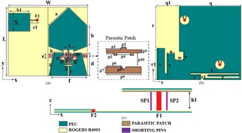
The proposed antenna design presents a pattern diversity UWB antenna for WBAN communications. The pattern diversity antenna is designed with a combination of a microstrip antenna and a monopole antenna suitable for both on-body/ off-body communication respectively. The monopole antenna with an omnidirectional radiation pattern is devised for providing better link connectivity between the body-worn devices and the microstrip patch antenna with a directional pattern will be more suitable for information exchange from on-body devices to external devices. The overall dimension of the proposed antenna is 40 × 34 × 2.54 mm3 as shown in Fig. 1. The antenna design contains stacked layers: the first layer with a HMPA backed with a parasitic patch in the second layer, while the third layer contains a monopole radiator. Both antennas are incorporated above the common ground plane as a bottom layer. The first layer, second layer, and third layer, bottom layer are separated by Rogers 4003C substrate with a thickness of 0.2 mm, ɛ r = 3.55, and loss tangent of 0.0027.
Proposed pattern diversity antenna design: (a) Front view (b) Rear view (c) Bottom view. The dimensions of the proposed antenna design are L = 34, W = 40, a = 13.4, a 1 = 9, b = 10.2, b 1 = 11, c = 5.2, c 1 = 4.2, d = 11.2, e = 2, f = 19.6, g = 11.6, h = 5.3, h 1 = 2, i = 5, j = 3.8, k = 1.6, l = 3.7, m = 2.2, n = 2.3, o = 1.1, p = 1.9, q = 28, q1 = 12, r = 19.5, r1 = 14.5, s = 14.5, t = 12, u = 3.5, v = 4, w = 4, x = 22.3, y = 14.7, z = 2.4, z 1 = 0.8, p 1 = 7.3, p 2 = 2.5, p 3 = 3.6, p 4 = 6.9, p 5 = 1.5, p 6 = 7.6, p 7 = 3, p 8 = 1.6, p 9 = 17, p 10 = 7 (All dimensions are in mm).

Design procedure of directional antenna
A microstrip patch antenna is the best candidate suitable for off-body communication providing the directional pattern with minimum back lobes but it results in a narrow bandwidth. The operating principle of the directional antenna is described as follows: To design a directional antenna, the center frequency of the UWB band is selected and a conventional narrowband patch antenna is designed to provide a narrowband at 6 GHz. When this patch antenna is incorporated with a coplanar waveguide (with the ground), it introduces quasi-TEM mode due to the air interface (2 mm) between conductor parts resulting in an increased number of modes at 3.1, 3.9, 4.3 and 5.6 GHz. To cover the entire UWB frequency range, the resonance coupling should take place in the entire band. Parasitic patches contribute to the bandwidth enhancement in the lower operating band (3.1–5.5 GHz) through capacitive coupling. Truncation has been implemented both in the coplanar waveguide and in the radiator, which helps in reducing overall antenna size and also improves impedance bandwidth (3.1–7.4 GHz). Thus, bandwidth can be further increased by introducing a connection between two conductor plates of coplanar waveguide (with the ground) to the backed ground plane using shorting pins. These shorting pins enhance capacitive coupling thereby paving the way for ultra-wideband with the help of the air gap between the top layer and bottom layer. Optimization is done by using a rectangular-shaped slit in the ground plane to remove unnecessary notches.
The evolution of the directional antenna is observed in Fig. 2 and explained in different stages as follows: Initially, a square patch antenna (Antenna I) is designed to provide the narrowband resonance at 6 GHz. To achieve the wide bandwidth, the patch antenna is coupled with a coplanar waveguide (Antenna II) to introduce quasi-TEM modes at lower frequencies such as 3.1, 3.9, 4.3, 5.6 GHz using an air interface between coplanar waveguide and ground plane. The T-shaped parasitic patches (TSPP) (Antenna III) backing the radiator are used to enhance the bandwidth of 3.1–5.5 GHz through the coupling. To obtain impedance matching in the entire UWB frequency range, truncation (Antenna IV) has been implemented both in the radiator and coplanar waveguide thereby the radiator is modified as a HMPA and the coplanar waveguide as a trapezoidal coplanar waveguide (TCP). The lower part and upper part of the radiator are truncated to provide a good impedance matching <10 dB in the mid-frequency range of 6.5–8 GHz and the lower frequency range from 4.75 to 6.5 GHz respectively. The coplanar waveguide is truncated to provide the impedance matching <6 dB for the upper-frequency range of 8–10 GHz. Thus, the truncation in the radiator and the coplanar waveguide results in good impedance matching in the lower & mid-frequency range and the upper-frequency range respectively. Optimization is performed to remove the notches through the slits and stubs (Antenna V) in the radiator and on a common ground plane. The stepped notch (SN) aids in achieving the impedance matching in the lower UWB frequencies. The reflection coefficient characteristics for each evolution stage of the proposed directional antenna are shown in Fig. 3.
Evolution of directional UWB antenna (a) Antenna I, (b) Antenna II, (c) Antenna III, (d) Antenna IV, (e) Antenna V.

Simulated reflection coefficient characteristics of evolution stages of the directional UWB antenna.

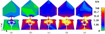
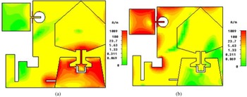
To better understand the evolution stages, the surface current distribution of the directional antenna is shown in Fig. 4. At 6 GHz, the current distribution is maximum near the feed line of the radiator. The coplanar waveguide present at the bottom of the radiator is observed with a high concentration of current at 5 GHz. The T-shaped parasitic patch backing the coplanar waveguide enhances the UWB bandwidth at the lower frequency region and the maximum current is concentrated at the parasitic patch near 3.5 GHz. The current is evenly distributed throughout the radiator, coplanar waveguide, and T-shaped parasitic patch at the center frequency of 7.5 GHz. The T-shaped slots and square slots in the coplanar waveguide aids in the optimization of the antenna and the high concentration of current is highly proliferated at the highest frequency of 10 GHz. Thus, the proposed HMPA with several broad banding techniques achieves the entire UWB frequency range.
Surface current distribution of the directional antenna (a) 6 GHz (b) 5 GHz (c) 3.5 GHz (d) 7.5 GHz (e) 10 GHz.

Design procedure of omnidirectional antenna
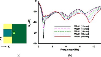
To facilitate on-body communication (data sharing between different body-worn devices), an omnidirectional pattern is quintessential. The design is based on simple compact monopole technology as shown in Fig. 5(a). The length of the monopole antenna corresponds to the lowest resonating frequency. The parameter sweep is performed by changing the width of the antenna to obtain good impedance matching in the entire UWB frequency range as shown in Fig. 5(b). From the figure, it can be inferred that the proposed antenna provides the entire UWB frequency range from 2 to 12 GHz.
(a) Monopole antenna (b) Parametric evolution of the monopole antenna.

MIMO configuration
MIMO technique gives a promising solution to mitigate the multipath fading effect caused by the movement of the human body parts and also provides a high data rate, throughput, and channel capacity. In the proposed antenna design, MIMO comprises two antenna elements configured in a single platform above an Inverted L-shaped conducting ground plane as shown in Fig. 6. The antenna elements are placed orthogonally to achieve good isolation >15 dB without the need for additional structure. To further improve isolation >20 dB in the entire UWB frequency range, slits are incorporated in the ground plane. This MIMO configuration achieves good impedance matching in the entire UWB frequency range from 3.1 to 10.6 GHz.
Overall configuration of the pattern diversity MIMO antenna.

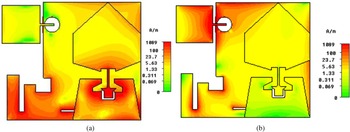
The coupling between the antennas is greatly reduced using the orthogonal arrangement and through modification in the ground plane. When port 1 is excited, and port 2 is terminated with load, the current distribution is maximum in the directional antenna and minimum in the omnidirectional antenna. Similarly, when port 2 is excited and port 1 is terminated with load, current concentration is maximum in the omnidirectional antenna and current flows to the unexcited antenna (antenna 1) are minimum. At the lowest frequency of 4 GHz, when port 1 is excited the current is maximum in the radiating part of the HMPA and along the periphery of the monopole antenna when port 2 is excited. Similarly, at the highest frequency of 10 GHz, the coplanar ground plane is observed with a maximum current when port 1 is excited and along the feed line of the monopole antenna when port 2 is excited. Figure 7 and Fig. 8 show the surface current distribution at 4 and 10 GHz. From the figure, it is inferred that good isolation is achieved between two antenna elements. Figure 9 shows the simulated reflection and isolation characteristics of the MIMO pattern diversity antenna. The simulated reflection coefficient characteristics (S 11 and S 22) of the proposed antenna cover the entire UWB frequency range from 3.1 to 10.6 GHz and isolation characteristics (S 12 and S 21) >20 dB in the entire UWB frequency range suitable for practical WBAN applications.
Surface current distribution at 4 GHz (a) port 1 (b) port 2.

Surface current distribution at 10 GHz (a) port 1 (b) port 2.

Simulated reflection and isolation characteristics of the pattern diversity antenna.

Results and discussions
Simulation and measurement
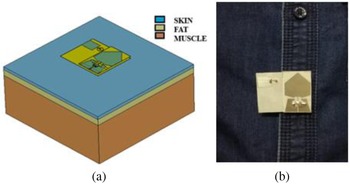
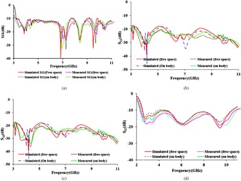
The front view and the bottom view of the fabricated prototype are shown in Fig. 10. The simulation is performed using CST studio suite 2018 and measurement has been done using Keysight's EC5071C Vector Network Analyzer (VNA). To evaluate the on-body performance, a rectangular human body model is simulated using stacked layers such as skin, fat, and muscle with different thicknesses, permittivity, and loss tangent using Table 1 [Reference Padmathilagam, Malathi, Shini, Rajesh, Gulam Nabi Alsath, Shanmathi, Sindhadevi and Sandeep Kumar17]. The proposed antenna is placed over the simulated human body model as shown in Fig. 11(a) and the results are observed. To obtain on-body measurement results, the proposed antenna is fixed on the abdomen of the human volunteer with a height of 155 cm and a weight of 60 kgs as shown in Fig. 11(b). The gap between the antenna and the human body model is maintained as 5 mm. Figure 12 provides the comparison of simulated and measured reflection and isolation characteristics performed on Free space (FS) as well as on-body (OB). From the figure, it is observed that the proposed antenna affords a good impedance matching and good isolation >20 dB in the entire UWB frequency range. Both the antenna elements provide the impedance bandwidth coverage of 7.5 GHz (3.1 to 10.6 GHz). Thus, the simulated results are in good agreement with the measured results highly suitable for practical WBAN applications.
Fabricated prototype of the proposed antenna (a) Front view (b) Bottom view.

(a) A rectangular human body model (b) On-body measurement of the proposed antenna.

Comparison of simulated and measured results in free space and on-body (a) Reflection characteristics-antenna 1(S 11) (b) Isolation characteristics (S 21) (c) Isolation characteristics (S 12) (d) Reflection characteristics-antenna 1(S 22).

Characterization of rectangular human body model at different frequencies

Radiation pattern
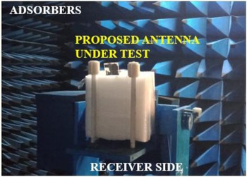
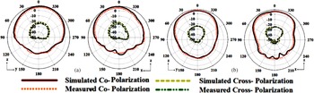
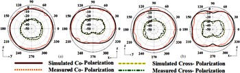
The radiation pattern is measured in the anechoic chamber as shown in Fig. 13. Figure 14 shows the comparison of simulated and measured radiation characteristics of the proposed HMPA antenna element. From the figure, it is inferred that the directional radiation pattern (maximum radiation directed outwards from the antenna) obtained becomes more suitable for off-body communication. Figure 15 provides the simulated and measured radiation characteristics of the monopole antenna element. The obtained omnidirectional pattern is highly suitable for on-body communication. Thus, the proposed pattern diversity antenna with distinct radiation characteristics becomes more adaptable for WBAN applications.
Radiation pattern measurement in an anechoic chamber.

Simulated and measured radiation pattern for the directional antenna, when port 1 is excited (a) 4 GHz, (b) 8 GHz.

Simulated and measured radiation pattern for the omnidirectional antenna, when port 2 is excited (a) 4 GHz, (b) 8 GHz.

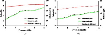
The simulated/ measured Gain and simulated efficiency of the proposed antenna are shown in Fig. 16. The simulated/measured gain and simulated radiation efficiency for the omnidirectional antenna obtained is about 2.2–4.6 dBi/2.1–4.5 dBi and 52–66.5% in the UWB frequency range. For the directional UWB antenna, the simulated/ measured gain is evaluated to be 2.5–7.5 dBi/2.45–7.3 dBi with a simulated efficiency of 74–86%. Gain and efficiency obtained from the proposed MIMO antenna become suitable for practical applications.
Gain and efficiency plot (a) Directional antenna (b) Omnidirectional antenna.

MIMO performance analysis
In MIMO antenna systems during simultaneous operation, neighboring or adjacent antenna elements interact with each other and this affects the overall efficiency and operating bandwidth. Thus it is necessary to analyze the MIMO performance metrics such as ECC, DG, and MEG. The amount of correlation and the mutual coupling between the antennas can be studied by a metric called ECC. It depends on the propagating medium and the far-field distribution. ECC can be calculated using far-field distribution as given by equation (1):

For an uncorrelated diversity antenna, the ECC should ideally be zero, but practically it is limited to be <0.5. The simulated ECC of the proposed antenna is observed to be <0.1 in the entire UWB frequency range. The DG is calculated to analyze how far the signal integrity can be improved. Using equation (2), the DG is calculated.

The DG obtained using the above formula is found to be >9.9 dB. The relative mean power levels from each antenna element for the signal transfer are measured using a metric known as MEG. For a good channel characteristic and diversity performance, the MEG ratio of two antenna elements should satisfy the criteria |MEG1/MEG2| = 1. The proposed antenna design provides MEG values approximately equivalent to 1.
SAR analysis
SAR (Specific Absorption Rate) is the rate of measuring the amount of radiation that penetrates the body tissues. The value of SAR should be less than 1.6 W/Kg per gram of tissue and 2 W/Kg for 10 grams of tissue. For the proposed antenna, the input power considered is 0.25 mW and the standard used is the IEEE C95.1 standard, averaged over 1 g of biological tissue. The proposed antenna is placed over the simulated rectangular human body model as shown in Fig. 11. Table 2 provides the SAR value with the distance between the antenna and the body tissue maintained as 3 and 5 mm. From the table, it can be depicted that the SAR simulation obtained at different frequencies is found to be less than 1.6 W/ Kg becomes more suitable for practical applications.
SAR values of the antennas at various distances from body tissue

The salient features of the proposed antenna are
(1) The proposed antenna design developed on a thin substrate reduces the vertical height of the antenna and provides lightweight thereby increasing human comfort in a real-time environment unlike in [Reference Sun, Cheung and Yuk1, Reference Kang, Wu and Tarng2, Reference Koohestani, Zürcher, Moreira and Skrivervik7, Reference Yang, Hu and Liu12, Reference Klemm, Kovcs, Pedersen and Troster15–Reference Mathur and Dwari24, Reference Wang, Ji, Gibbins and Yin27, Reference Kumar Biswas and Chakraborty28].
(2) In contrast to [Reference Klemm, Kovcs, Pedersen and Troster15–Reference Padmathilagam, Malathi, Shini, Rajesh, Gulam Nabi Alsath, Shanmathi, Sindhadevi and Sandeep Kumar17], the proposed microstrip antenna with the aid of the broad banding techniques provides directional characteristics in the entire UWB frequency range.
(3) Good isolation characteristics are achieved between antenna elements with a minimum interelement spacing and without the need for any additional structure unlike as in [Reference Joo, Kwon and Choi18–Reference Dabas, Gangwar, Kanaujia and Gautam22, Reference Mathur and Dwari24, Reference Wang, Ji, Gibbins and Yin27, Reference Kumar Biswas and Chakraborty28].
(4) The proposed MIMO antenna design offers both directional and omnidirectional radiation characteristics suitable for both on-body and off-body communication dissimilar to [Reference Joo, Kwon and Choi18–Reference Mathur and Dwari24, Reference Wang, Ji, Gibbins and Yin27–Reference Subbaraj, Ramalingam, Kanagasabai, Sundarsingh, Selvam and Kingsley33].
(5) In contrast to [Reference Dabas, Gangwar, Kanaujia and Gautam22, Reference Mathur and Dwari24], the proposed design provides symmetric geometry with a respective axis from the port position, hence current distribution is evenly distributed thus paving a way for symmetric radiation patterns.
(6) Gain and efficiency obtained from the proposed antenna design become more suitable for practical applications dissimilar to [Reference Prudhvi Nadh, Madhav, Siva Kumar, Venkateswara Rao and Anilkumar4, Reference Joo, Kwon and Choi18–Reference Mathur and Dwari24, Reference Wang, Ji, Gibbins and Yin27–Reference Subbaraj, Ramalingam, Kanagasabai, Sundarsingh, Selvam and Kingsley33]. Table 3 provides the comparison of the proposed antenna with existing literature.
Comparison with existing literature

Bold represents the significance of the present work.
Conclusion
A compact pattern diversity UWB antenna for WBAN application is discussed in a detailed manner. The proposed pattern diversity antenna provides both omnidirectional and directional radiation characteristics suitable for on-body/off-body communication with transmitting and reception capabilities. Good impedance matching and isolation are observed over the entire UWB band. The measured results are in good agreement with the simulation ones. The integration of the MIMO technique provides a high data rate, throughput, and channel capacity. The exciting features of the proposed pattern diversity antenna such as low profile, high isolation, pattern diversity, and good diversity performance make it highly recommended for practical wireless body area communication services.
Acknowledgement
The authors thank Mr. Vikneshwaran for the help rendered during the initial stages of the antenna design.
 Malathi Kanagasabai completed her B.E.-Eelectronics and communication engineering and M.E.- Microwave and optical engineering from A C Tech, Karaikudi in the years 1988 and 1990, respectively. She received her Ph.D. on “Analysis of Rectangular Shielded Stripline Enclosures” from Anna University, Chennai in 2004. She currently serves as a professor in the Department of Electronics and Communication Engineering (ECE), Anna University, Chennai. Her research interests are antennas, UWB microwave components, electromagnetic shielding and signal integrity analysis in RF printed circuit boards.
 Padmathilagam Sambandam obtained the M.E. degree in communication systems from College of Engineering, Guindy, Anna University, Chennai and currently working as a research scholar. Her research interests are microwave sensors, microwave devices, and WBAN antennas.
 Mohammed Gulam Nabi Alsath obtained his B.E. and M.E. degree from the College of Engineering Anna University, Chennai. He received his Ph.D. degree from Anna University for his research work on automotive antennas. He currently serves as an associate professor in the Department of ECE, Sri Sivasubramaniya Nadar College of Engineering, Chennai. His research interests include microwave components and circuits, antenna engineering, signal integrity analysis and solutions to EMI problems.