I. INTRODUCTION
With the development of global economic integration, global resources have been becoming increasingly scarce. To achieve the purpose of energy-saving and emission-reduction, the strategy of vehicle lightweight has become a national trend in transportation industry. Recently, the realization approaches and key technologies to achieve the vehicle lightweight at home and abroad mainly include three aspects: one is lightweight structure design and optimization, the second is the application of lightweight materials and the third is the use of new manufacturing techniques. Ultrahigh strength steel is major auto lightweight material, followed by aluminum alloy, magnesium alloy, composite material and plastic, etc. Therefore, in vehicle design and manufacture, using lightweight structure design and increasing the ultrahigh strength steel, aluminum alloy, and magnesium alloy in the use of lightweight materials are the most direct and effective way to realize the vehicle lightweight, energy-saving, environmental protection, and safety. Reference Nishimoto, Okumoto, Harano, Atagi, Fujii and Katayama1–Reference Schubert, Klassen, Zerner, Walz and Sepold4 Aluminum–steel dissimilar metal structure can give full play to respective advantages of aluminum and steel. It has merits of light weight, high strength, good thermal conductivity, and good economic returns. And the joining of aluminum alloy to steel has attracted wide publicity and shows a bright prospect in fields of aerospace, shipbuilding, and automobile manufacturing. As a consequence, the dissimilar metal joining of aluminum alloy to ultrahigh strength steel becomes the key problem to be solved. However, the dissimilar metal joining of aluminum to steel is very difficult due to the formation of brittle and hard Fe–Al intermetallic compounds (IMCs) in the interface. Reference Taban, Gould and Lippold5–Reference Song, Lin, Yang and Fan7
In the recent study, various welding processes have been conducted to hopefully address this issue. To obtain a high-quality joint of aluminum and steel, some welding methods have been studied. Lin et al. Reference Lin, Song, Yang, Fan and Zhang8 joined 5A06 aluminum alloy and SUS321 stainless steel by tungsten inert gas arc welding (TIG) method, and proved that the IMC layer consisted of Fe4Al13 phase. Su et al. Reference Su, Hua and Wu9 joined 5052 aluminum alloy to galvanized mild steel by gas metal arc welding, and pointed that the addition of Si can suppress the growth of IMC layer and the generation of hot cracks effectively. Zhang et al. Reference Zhang, Sun, Han, Gao and Qiu10,Reference Zhang, Sun, Han and Liu11 joined the 6008-T66 aluminum alloy to high strength steel by resistance spot welding, and suggested that Fe2Al5 and Fe4Al13 phases appeared in the interfacial layer. Friction welding, Reference Balalan, Ozdemir, Firat and Caliguhu12 friction stir welding, Reference Liu, Lan and Ni13 cold pressure welding, Reference Cao, Sun, Chen and Wang14,Reference Liu, Sun, Liu, Wang and Feng15 laser welding Reference Ma, Harooni, Carlson and Kovacevic16 and hybrid laser welding Reference Lei, Wang, You, Qin, Wang and Lin17–Reference Yan, Gao and Zeng19 were also used for joining aluminum alloy to stainless steel, carbon steel, galvanized steel, and high strength steel. However, up to now, the report dealing with joining of aluminum alloy and ultrahigh strength steel is very limited.
The metal inert-gas arc welding (MIG welding) is widely applied in automobile and railway vehicle industries for its high efficiency, low cost, and good applicability for the geometry and size of workpiece. The present work investigates the dissimilar MIG welding of 6082 aluminum alloy and SYG960E ultrahigh strength steel using Al–Mg and Al–Cu welding wires. Its purpose is to better understand the weldability of aluminum alloy and ultrahigh strength steel, and to provide some foundation for improving mechanical properties of the Al–steel joints.
II. EXPERIMENTAL
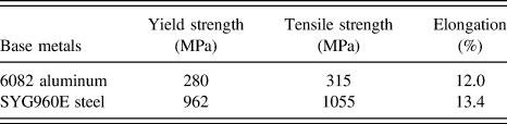
In this investigation, the base metals used were the 6082 aluminum alloy and SYG960E ultrahigh strength steel with 4 mm in thickness, and ER5087 Al–Mg welding wire and ER2319 Al–Cu welding wire were used as filler metals. The chemical compositions of base metals and filler metals, and the mechanical properties of base metals are listed in Table I, II and III, respectively.
Chemical compositions of base metals (wt%).

Chemical compositions of welding wires (wt%).

Mechanical properties of base metals.

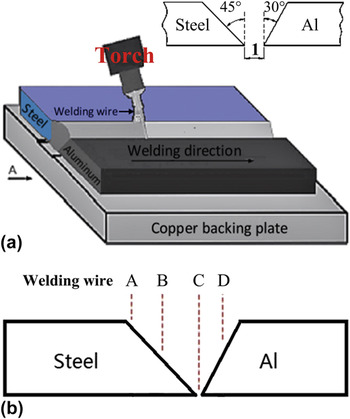
Prior to welding, the base metal plates were cut into dimensions of 150 × 50 mm, with a 30° bevel angle on aluminum alloy and a 45° bevel angle on steel to form a single-V groove. The surfaces of grooves were cleaned by different types of sandpapers and acetone, and both plates were assembled in butt configuration with a root gap of 1 mm, as shown in Fig. 1(a).
The schematic of MIG welding (a) and different positions of welding wire (b).

Experiments were carried out by automatic MIG with the welding current of 95–115 A, welding speed of 50 cm/min, Ar shielding gas flowing of 20 L/min and the angle of welding torch of 45° using Al–Mg and Al–Cu welding wires, respectively. In the experiments, the welding wire position was changed for A, B, C, and D to evaluate its effect on weld appearance, as shown in Fig. 1(b).
After MIG welding, the specimens of Al–steel joints were cut into dimensions of 10 × 15 mm vertical to the welds, and then were ground, polished, and etched by Keller reagent for metallographic examination. The microstructures of the Al–steel joints were examined using optical microscope (OLYMPUS-PMG3, Olympus Optical Co. Ltd., Tokyo, Japan) and scanning electron microscope (SEM; JSM-5310, JEOL Ltd., Tokyo, Japan). The chemical and phase compositions of weld and interface layer were determined by energy dispersive spectrometer (EDS; Link-ISIS, Oxford Instruments, Oxfordshire, United Kingdom) and X-ray micro-diffraction (XRD; Discover with GADDS, PANalytical B.V., Almelo, The Netherlands). The microhardness of the joints was measured at the load of 100 g and the duration time of 10 s. The tensile tests were carried out at room temperature by means of MTS 810 material test system, and the joint strength was determined based on the average of three measurements per condition. After the tensile tests, the fractured surfaces of Al–steel joints were examined by SEM.
III. RESULTS AND DISCUSSION
A. Weld appearance and joint microstructures
1. Weld appearance
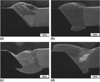
The appearance of weld is one of important factors to evaluate welding quality. The experimental results indicated that the position of welding wire (welding torch) had a significant effect on the weld appearance for MIG welding of aluminum alloy and ultrahigh strength steel. Figure 2 shows weld appearances produced in different welding wire positions [Fig. 1(b)] at the welding current of 105 A and welding speed of 50 cm/min. When the welding wire was in position A (top of steel groove), the small root reinforcement and incomplete joining defect at bottom of Al/steel interface were observed [Fig. 2(a)]. It can be explained by the steel groove bottom having lower peak temperature of weld thermal cycle than the steel groove top. Reference Wang, Sun, Yin and Liu20 The weld appearance was improved at position B of welding wire (middle of steel groove), as shown in Fig. 2(b). When the welding wire was in the position C (groove root) and position D (middle of Al groove), the incompletely filled weld, incomplete fusion and undercut defects appeared [Figs. 2(c) and 2(d)], which deteriorates not only the weld appearance but also Al–steel joint properties. These results suggested that it is necessary to select suitable welding wire position and it is favorable to put the welding wire toward the middle of steel groove for improving the weld appearance and mechanical properties of Al–steel joints.
Weld appearances in different welding wire positions: (a) position A, (b) position B, (c) position C, and (d) position D in Fig. 1(b).

2. Joint microstructures
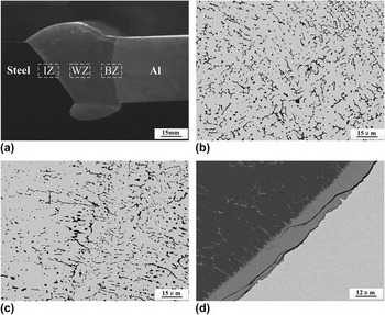
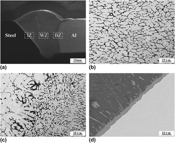
Figures 3 and 4 illustrate typical cross sections and microstructures of MIG welded joints of 6082 aluminum alloy and SYG960E ultrahigh strength steel using Al–Mg and Al–Cu welding wires, respectively. From Figs. 3(a) and 4(a), it can be seen that the Al–steel joints have welding–brazing characteristics. During MIG welding, the aluminum alloy base metal and welding wire were molten to form aluminum weld and bond zone (BZ) at aluminum alloy side, while the ultrahigh strength steel remained solid and the aluminum was joined to steel by wetting and spreading of molten aluminum on steel surface to form brazing interface layer. According to the welding–brazing characteristics, the Al–steel joints can be divided into three zones: weld zone (WZ), bond zone (BZ), and interface zone (IZ).
Microstructures of Al–steel joint with Al–Mg welding wire: (a) joint cross section, (b) WZ, (c) BZ, and (d) IZ.

Microstructures of Al–steel joint with Al–Cu welding wire: (a) joint cross section, (b) WZ, (c) BZ, and (d) IZ.

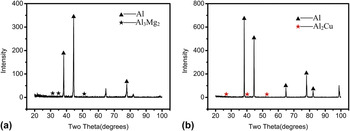
Fig. 3(b) and 4(b) show the microstructures of WZs with Al–Mg and Al–Cu welding wires, respectively. As can be seen, both welds have finer grains compared with the aluminum alloy base metal, which is mainly associated with the welds having quick cooling rate. The XRD results (Fig. 5) indicated that the weld with Al–Mg welding wire consisted mainly of α-Al solid solution and β-Al3Mg2 phase, and it mainly contained α-Al and Al2Cu phases when the Al–Cu welding wire was used, the Al3Mg2 and Al2Cu phases mainly distributing in α-Al grain boundaries. From Figs. 3(c) and 4(c), it can be seen that the welds have good metallurgical bond with aluminum base metal without welding defects such as lack of fusion and cracks in BZs. The thickness of BZs is 10–20 μm and the welding wires have little effect on it. There exists an evident IZ between aluminum weld and steel base metal, as shown in Figs. 3(d) and 4(d). The morphology of IZ is irregular and it has a double-layer structure characteristic, a needle-like structure close to the aluminum weld and a lath-shaped structure near the steel base metal. In this investigation, it was found that the composition of welding wire had great effects on the Al/steel interface layer. The Al–Mg welding wire resulted in forming the thick interface layer and cracks were observed in the interface layer [Fig. 3(d)]. When the Al–Cu welding was used, the thickness of interface layer decreased obviously, and the cracks disappeared from the interface layer [Fig. 3(d)], which means that the Cu can restrain the growth of interface layer and improve its cracking sensitivity.
XRD patterns of WZs with Al–Mg and Al–Cu welding wires: (a) Al–Mg welding wire and (b) Al–Cu welding wire.

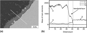
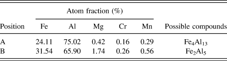
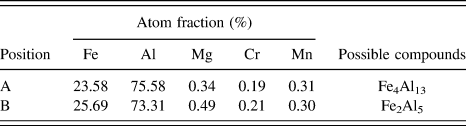
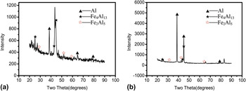
Fig. 6 and 7 show interface layers produced with Al–Mg and Al–Cu welding wires, respectively, and EDS linear scanning analysis results across the interface layers. The results indicated that from aluminum side to steel side, the Al concentration decreased while the Fe concentration increased gradually in the interface layers, and the interface layers contained higher Al concentration and lower Fe concentration at Al side than those at steel side, demonstrating that the interdiffusion of Al and Fe occurred in the Al/steel interface during welding. Tables IV and V present EDS analysis results of region A and region B in the interface layers shown in Figs. 6(a) and 7(a), respectively. The atom percentages of Fe and Al are 24.11 at.% and 75.02 at.% in the region A in Fig. 6(a) and 23.58 at.% and 75.58 at.% in the region A in Fig. 7(a), which corresponds to Fe4Al13 interval in the Al–Fe binary alloy phase diagram. Similarly, the region B in Figs. 6(a) and 7(a) contains 31.54 at.% Fe and 65.90 at.% Al (Table IV) and 25.69 at.% Fe and 73.31 at.% Al (Table V), respectively, and hence they should consist mainly of Fe2Al5 IMC. The Micro-X-ray diffraction was used to identify phase compositions of interface layers. Figure 8 shows XRD results of interface layers with Al–Mg and Al–Cu welding wires. Fe2Al5 and Fe4Al13 phases were detected in the interface layers, indicating that the interface reaction happened to form Al–Fe IMCs during welding.
The interface layer with Al–Mg welding wire and EDS analysis results across the interface layer: (a) interface layer and (b) EDS analysis results.

The interface layer with Al–Cu welding wire and EDS analysis results across the interface layer: (a) interface layer and (b) EDS analysis results.

EDS analysis results of interface layer in Fig. 6(a).

EDS analysis results of interface layer in Fig. 7(a).

XRD results of interface layers with (a) Al–Mg and (b) Al–Cu welding wires.

Based on results above, it is concluded that the Al/steel interface reaction is necessary for joining aluminum alloy to ultrahigh strength steel, the IZ has a double-layer structure consisting of needle-like Fe4Al13 layer at aluminum side and lath-shaped Fe2Al5 layer at steel side, the excessive Al–Fe IMCs increase cracking sensitivity due to their brittleness and the Cu can decrease interface layer thickness and improve its cracking sensitivity. It should be pointed out that effects of Cu on interface layer are related to affecting atom diffusion and forming (Fe, Cu)4Al13 and (Fe, Cu)2Al5. During welding, the Cu atoms deposited on the surface of Fe4Al13 to block the interdiffusion of Fe and Al atoms, thus restraining the growth of Al–Fe IMCs and resulting in decreasing the thickness of interface layer. At the same time, the formed (Fe, Cu)4Al13 and (Fe, Cu)2Al5 lowers the hardness and brittleness of Al–Fe IMCs. Reference Song, Lin, Yang, Fan and Ma21 Therefore, it is favorable to use Al–Cu welding wire for improving microstructures and cracking sensitivity of the Al–steel joints.
B. Effects of welding parameter and welding wire composition
According to microstructural characteristics of MIG welded joints of aluminum alloy and ultrahigh strength steel, the interface IMC layer is the weakest region in the Al–steel joints. The experimental results indicated that the welding parameter (welding current) and welding wire composition had great effect on the interface layer.
Figure 9 shows the morphology of interface layers produced with different welding currents and welding speed of 50 cm/min using Al–Mg wire. When the welding current was 95 A, a large number of incomplete brazing defects were observed at Al/steel interface due to the low heat input resulting in insufficient interface reaction [Fig. 9(a)]. With increasing of welding current from 95 A to 115 A, the thickness of interface layers increased from 6 μm to 18 μm, and the continuous crack formed in the interface layers, which is mainly associated with increased heat input. The larger the welding current is, the higher the heat input is, resulting in increasing the temperature and reaction time of Al/steel interface, and hence accelerating growth of the interface layer. Meanwhile, the increased heat input also enhances the tensile stress in the Al–steel joints, which facilitates the initiation and propagation of cracks in the brittle IMC layers.
The morphology of interface layers at different welding currents using Al–Mg welding wire: (a) 95 A, (b) 105 A, (c) 110 A, and (d) 115 A.

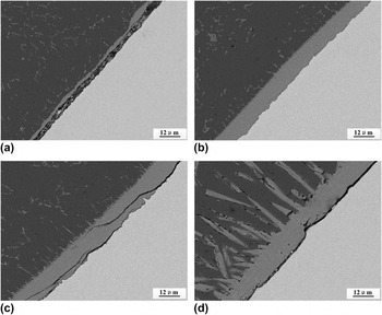
When the Al–Cu filler wire was used, the interface layer thickness and cracking sensibility decreased obviously at different welding currents, as shown in Fig. 10. At low welding current (95 A), the thickness of interface layer was less than 2 μm and there existed local incomplete brazing defects at Al/steel interface [Fig. 10(a)]. A continuous interface layer with about 3 μm in thickness formed at welding current of 100 A [Fig. 10(b)]. Further increasing the welding current to 115 A, the thickness of interface layer increased to 10 μm and the cracks appeared in the interface layer [Fig. 10(d)], which is related to the larger heat input leading to forming excessive Al–Fe IMCs and enhancing the tensile stress in the Al–steel joint. Therefore, the larger the welding current and excessive IMCs should increase the cracking sensibility of Al–steel joint and deteriorate its mechanical properties. Compared with those with Al–Mg welding wire, the decreased interface layer thickness and cracking sensibility with Al–Cu filler wire are attributed to the formed (Fe, Cu)4Al13 and (Fe, Cu)2Al5 restraining the growth of interface layer and lowering the hardness and brittleness of IMCs.
The morphology of interface layers at different welding currents using Al–Cu welding wire: (a) 95 A, (b) 100 A, (c) 105 A, and (d) 115 A.

C. Mechanical properties of joints
1. Joint microhardness
Figure 11 illustrates the microhardness profiles across MIG welded joints of 6082 aluminum alloy and SYG960E ultrahigh strength steel using Al–Mg and Al–Cu welding wires, respectively. As can be seen, the microhardness distribution of the joints is very nonuniform. The average hardness values of aluminum and steel base metals were 72.6 HV and 325.8 HV, respectively. The welds had the microhardness of 50.8–80.5 HV. The highest hardness values of the joints appeared in the IZs due to containing hard Fe4Al13 and Fe2Al5 IMCs. The IZ hardness (424.2 HV) with Al–Cu welding wire is lower than that (447.1 HV) with Al–Mg welding wire, confirming the formed (Fe, Cu)4Al13 and (Fe, Cu)2Al5 lowering the hardness of Al–Fe IMCs.
Microhardness profiles across MIG welded Al–steel joints with Al–Mg and Al–Cu welding wires: (a) Al–Mg filler wire and (b) Al–Cu filler wire.

D. Joint tensile strength
The experimental results indicated that the welding current and welding wire composition had great effect on the tensile strength of Al–steel joints. Figure 12 shows the effect of welding current on joint strength using Al–Mg and Al–Cu welding wires, respectively. From Fig. 12(a), it can be seen that at low welding current (100 A), the Al–steel joint with Al–Mg welding wire gave the poor tensile strength of 58 MP due to the local incomplete brazing defects at Al/steel interface. The joint strength was increased to 65 MPa at welding current of 105 A. When the welding current was larger than 105 A, the joint strength deteriorated seriously. It can be explained by forming excessive Al–Fe IMCs and cracks in the interface layers. The former facilitates the initiation and propagation of cracks under tensile stress and the latter not only provides preferential sites for the initiation and propagation of cracks but also decreases the effective cross-sectional area of the joints. Figure 12(b) shows the effect of welding current on Al–steel joint strength with the Al–Cu welding wire. As can be seen, the change of joint strength with increasing welding current was similar to that with Al–Mg welding wire. The joint strength reached 128 MPa at the welding current of 100 A, which increased by 97% compared with that with Al–Mg filler wire. It is mainly attributed to the formed (Fe, Cu)2Al5 and (Fe, Cu)4Al13 improving the brittleness of Al–Fe IMCs in the interface layer and eliminating interface layer cracks.
The effect of welding current on joint strength using Al–Mg and Al–Cu filler wires: (a) Al–Mg filler and (b) Al–Cu filler wire.

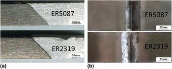
Figure 13 and 14 show the morphology of fractured joints after tensile tests and XRD results on fracture surfaces of the joints with Al–Mg and Al–Cu welding wires, respectively. These results demonstrated that the joint fracture mainly occurred at interface IMC layer and it was the weakest region in the joints of 6082 aluminum alloy and SYG960E ultrahigh strength steel. Figure 15 shows the fracture surface morphologies of Al–steel joints with Al–Mg and Al–Cu welding wires. From Fig. 15(a) the fracture surface displays the representative flat nature of a brittle cleavage surface and some microcracks were observed on the fracture surface. In contrast to Fig. 15(a), the fracture surface with Al–Cu filler wire has some features of plastic deformation, confirming the formed (Fe, Cu)4Al13 and (Fe, Cu)2Al5 lowering the brittleness of Al–Fe IMCs.
The fracture of Al–steel joints with Al–Mg and Al–Cu filler wires: (a) the fracture site and (b) the macroscopic morphologies of fracture surface.

XRD results on fracture surfaces of Al–steel joints with Al–Mg and Al–Cu welding wires: (a) Al–Mg welding wire and (b) Al–Cu welding wire.

Fracture surface morphologies of Al–steel joints with Al–Mg and Al–Cu welding wires: (a) Al–Mg filler wire and (b) Al–Cu filler wire.

IV. CONCLUSIONS
-
(1) The welding wire position has a significant effect on weld appearance for MIG welding of aluminum alloy and ultrahigh strength steel. It can be improved when the welding wire is directed toward the middle of steel groove. The Al–steel joints have welding–brazing characteristics and mainly include the WZ, BZ, and IZ. The phase compositions of WZs with Al–Mg and Al–Cu welding wires are α-Al and β-Al3Mg2, and α-Al and Al2Cu, respectively. The IZs consist mainly of needle-like Fe4Al13 layer at Al side and lath-shaped Fe2Al5 layer at steel side. The interface layer thickness and cracking sensibility of joints with Al–Cu welding wire decrease compared with those with Al–Mg welding wire, which is related to the Cu restraining the growth of interface IMC layer and lowering its hardness and brittleness.
-
(2) The welding current and welding wire composition (Al–Mg and Al–Cu) have great effect on the interface IMC layer. With increasing of welding current, the thickness of interface layers and cracking sensitivity of joints increase due to the enhanced heat input and tensile stress in the joints. The interface layer thickness and cracking sensitivity of joints with Al–Cu welding wire decrease compared with those with Al–Mg welding wire, which is related to the Cu restraining the growth of interface IMC layer and lowering its hardness and brittleness.
-
(3) The welding current and welding wire composition have great effect on mechanical properties of Al–steel joints. The highest hardness of the joints appeared in IZs due to containing hard Al–Fe IMCs. The joint strength increases with increasing welding current, and it decreases obviously when the welding current is larger than 105 A. The joint strength with Al–Mg and Al–Cu welding wires can reach 65 MPa and 128 MPa, respectively. It is favorable to use Al–Cu welding wire for improving microstructures, cracking sensitivity, and mechanical properties of the Al–steel joints.
ACKNOWLEDGMENT
The authors would like to thank National Natural Science Foundation of China (No. 51275204) for the financial support.