Introduction
In the past few decades, technological advancement in the medical field has facilitated human lives significantly. Implantable medical devices (IMDs) are gaining the researcher's attention for the betterment of human health. IMDs can be implanted inside the human body tissue to collect the human body's physiological data [Reference Liu, Guo and Xiao1]. These IMDs consist of an implantable patch antenna that transmits the physiological data to the receiver device outside the human body. There are numerous uses for IMDs, including monitoring of intracranial pressure (ICP), cardiac pacemakers, glucose monitoring, and capsule endoscopy [Reference Yang, Xiao, Zhu, Wang and Tu2–Reference Cho and Yoo6].
Additionally, it has various clinical uses, including neural recording and retinal prosthesis [Reference Yang, Xiao, Zhu, Wang and Tu2]. While designing the implantable patch antenna, several challenges include compact size, wide bandwidth, high gain, stable pattern, and low specific absorption ratio (SAR) for patient safety [Reference Faisal, Zada, Ejaz, Amin, Ullah and Yoo7, Reference Liu, Guo and Xiao8]. To implant the patch antenna inside the human tissue, the antenna is miniaturized to make it as compact as possible by considering its effect on antenna performance parameters such as reflection coefficient, impedance bandwidth, gain, and SAR value [Reference Kumar, Singh and Singh Chauhan5]. In some prior work [Reference Liu, Guo and Xiao1, Reference Yang, Xiao, Zhu, Wang and Tu2, Reference Li, Yong and Xiao9], the volume of the antenna is 127 mm3 (10 × 10 × 1.27 mm3). In this work, a compact size of 50 mm3 (10 × 10 × 0.5 mm3) is achieved with wide impedance bandwidths, which are better than [Reference Liu, Guo and Xiao1, Reference Yang, Xiao, Zhu, Wang and Tu2, Reference Li, Yong and Xiao9, Reference Liu, Wu, Fan and Tentzeris10]. Circular polarization is more challenging to accomplish than other patch antenna characteristics when there is a need for miniaturization along with biocompatibility [Reference Xia, Li, Lee, Xiao, Shao and Ding3]. In this work, circular polarization is achieved at the ISM band. Since the human body is highly complex, the permittivity and conductivity are different for different human tissue types. As both permittivity and conductivity are frequency-dependent, a shift in the antenna's resonant frequency is observed when implanted into different tissues [Reference Kiourti, Nikita and Nikita11]. Xia et al. [Reference Xia, Li, Lee, Xiao, Shao and Ding3] used C-shaped slots with two shorting pins, while Yang et al. [Reference Yang, Xiao, Zhu, Wang and Tu2] used thin slits on the patch with three shorting pins to achieve circular polarization.
The presented antenna has been designed and simulated within the human skin tissue phantom and the head scalp tissue phantom. In this work, miniaturization, CP realization, and bandwidth enhancement are achieved by using patch meandering to lengthen the current path [Reference Kim and Shin12]. Patient safety is a crucial concern while designing the implantable patch antenna; that's why SAR is investigated in this work. With these SAR values, maximum allowable input powers are calculated. The designed antenna is implanted at a depth of 4 mm within the homogenous skin phantom and human scalp phantom to conduct all simulations and measurements. The presented antenna is compared with some existing works in Table 1.
Comparison of the presented work with some existing works

Methodology
Implantable antenna design
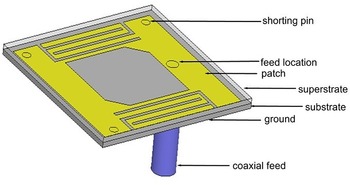
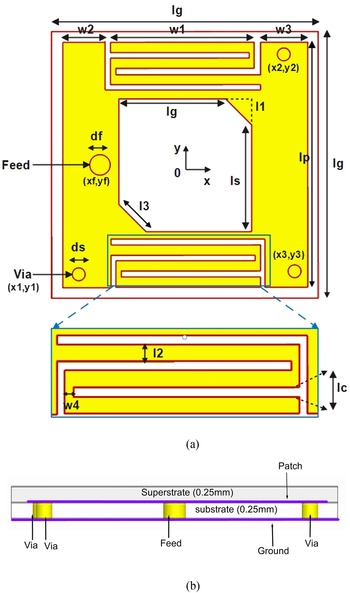
The demonstrated antenna is intended to resonate within the ISM band (2.4–2.48 GHz). The compact size of the proposed antenna is 50 mm3, i.e., 10 mm × 10 mm × 0.5 mm as illustrated in Fig. 1. The details of geometry and dimensions are depicted in Fig. 2 and Table 2. The proposed antenna design is evolved in a stepwise manner. In the first step, a simple square patch has been designed. At this step, the antenna resonates at 4.1 GHz. In the second step, a central square of 5 mm × 5 mm is cut into the patch, leading to a shift in resonating frequency from 4.1 to 3.4 GHz. In the next step, two shorting pins are used to connect the patch to the ground at opposite corners. This has resulted in a further shift in resonant frequency up to 2.8 GHz. In order to achieve a stable radiation pattern and better axial ratio bandwidth, two perturbation elements are inserted at opposite corners of the square cut in the patch. In the final step, the desired resonating frequency of 2.45 GHz is achieved by introducing the meander-line slots at symmetrically opposite sides of the patch. A significant improvement in impedance matching is observed by introducing the third shorting pin. Rogers 6010 (ɛr = 10.2, tan δ = 0.0023) with 0.25 mm thickness used for both substrate and superstrate. A cylindrical PEC material with a diameter of 0.7 mm is used for the 50 Ω coaxial feed to the patch antenna. The main advantage of this feeding is that feed can be placed anywhere inside the patch to achieve high impedance matching. Shorting pins (via) that connect patch and ground are used to achieve miniaturization, leading to a significant shift in resonating frequency to the lower bands [Reference Yang, Xiao, Zhu, Wang and Tu2]. To prevent the antenna's direct contact with human tissue, it is enclosed in a biocompatible material. In this work, Al2O3 (ɛr = 9.8), which is 0.25 mm thick, is used as a biocompatible material for encapsulating the patch antenna [Reference Gani and Yoo13]. All the dimensions of the design, coaxial feed location, and shorting pin positions are optimized by doing parametric analysis to achieve the best possible results.
The architecture of the proposed implantable patch antenna.

(a) Detailed dimensions of the proposed antenna. (b) Proposed antenna with side view.

Optimized dimension values of the antenna

Simulation setup
The designed antenna is studied inside the human tissue phantom. The patch antenna is embedded into a homogeneous skin phantom whose complex environment differs from free space. A one-layered cubical phantom with a dimension of 90 × 90 × 25 mm3 is used as a human tissue model shown in Fig. 3. The antenna is embedded at a depth of 4 mm inside the skin tissue phantom and head scalp phantom to carry out all the simulations and observations. Table 3 lists the dielectric characteristics of several human tissues [Reference Yang, Xiao, Zhu, Wang and Tu2].
Simulation setup for proposed implantable patch antenna.

Dielectric characteristics of several human tissues [Reference Yang, Xiao, Zhu, Wang and Tu2]

Results and discussion
Simulated results
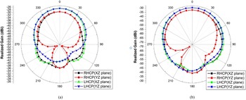
The Ansoft HFSS software tool is used to obtain all the simulation results. Figure 4 shows the effect on reflection coefficient (S 11) when the patch antenna is embedded in homogeneous skin phantom at different depths (D). By parametric analysis, the implanting depth of the antenna is varied and it is observed that the best impedance matching is occurring at 4 mm depth within the human tissue. Hence, the designed antenna is embedded at 4 mm depth inside the human tissue phantoms as it provides the best possible optimized results. As seen in Fig. 5, the S 11 is −33.49 and −39.9 dB with impedance bandwidth (S 11 ≤ 10 dB) of 52.63 and 53.44% inside homogeneous skin phantom and human scalp phantom, respectively. The suggested antenna is also simulated in the free space. It can be seen that it does not radiate there, which is evident by the fact that S 11 is nearly zero in the 1–3 GHz frequency range, as shown in Fig. 5. The circular polarization is observed in the skin and scalp tissue, as shown in Fig. 6. The obtained 3 dB AR bandwidth is 15.44 and 20.08%, respectively. The suggested antenna has a maximum peak gain of −25.18 dB at 2.47 GHz inside a human skin phantom and −28.12 dB at 2.42 GHz in the human scalp phantom. Figure 7 depicts the realized gain pattern of the antenna in both tissue phantoms.
Reflection coefficient (dB) when the antenna is embedded at different depths (D) in homogeneous skin phantom.

Reflection coefficient (dB) when the antenna is embedded at a 4 mm depth.

Axial ratio when the antenna is embedded at 4 mm depth.

Simulated realized gain pattern at 2.45 GHz (a) in human skin phantom, (b) in human scalp phantom.

Effect of coating material
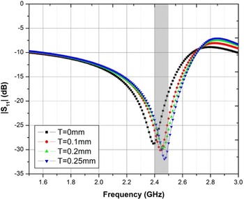
The antenna is encapsulated within a biocompatible material to avoid direct contact of the implantable device with human tissue. The effect of thickness of coating material is examined as shown in Fig. 8. Al2O3, which has a high dielectric value and a low loss tangent, is utilized as a biocompatible material in this work. As shown in Fig. 8, the antenna parameters varied with the change in thickness of the coating material. The antenna performs well with the proposed thickness of 0.25 mm coated over the presented implantable patch antenna.
Variation of S 11 when the antenna is encased with Al2O3 coating with various thicknesses (T).

Analysis of SAR
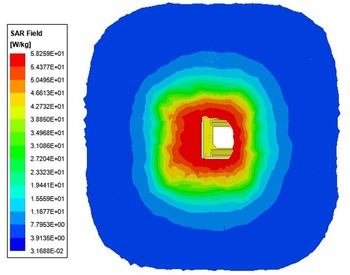
For patient safety concerns, SAR is observed while implanting the antenna in different human tissues. The SAR analysis of the presented antenna is summarized in Table 4. According to IEEE standard C95.1-2019, the maximum allowable SAR should be <2 W/kg for 10 g of human tissue [14]. The maximum allowable input power should be >25 μW for biomedical applications [Reference Yang, Xiao, Zhu, Wang and Tu2]. SAR is also dependent on the input power applied to the antenna so, if the lesser input power is provided, the SAR value will also be less. In HFSS simulation, when 1 W of input power is provided, the simulated SAR values are obtained as 58.259 and 58.013 W/kg for 10 g of homogeneous skin phantom and human scalp phantom, respectively, as shown in Figs 9 and 10. To bring the SAR values under the limits of 2 W/Kg, we can provide maximum input powers up to 34.32 and 34.47 mW, respectively. So, by providing the input powers up to 34.32 and 34.47 mW, respectively, the maximum SAR for the proposed antenna is under the limits of 2 W/kg. These input powers are much greater than the allowable input power of 25 μW intended for biomedical implantable antenna applications. [14]. Hence, obtained SAR values is under the limitations provided by IEEE standard.
SAR (with 1 W input power) for 10 g of skin tissue phantom at 2.45 GHz.

SAR (with 1 W input power) for 10 g of scalp tissue phantom at 2.45 GHz.

Maximum SAR values (for 1 W input power) and maximum allowable input powers (up to which SAR values under 2 W/kg limit)

Measured results
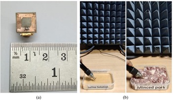
The measurement setup of the fabricated antenna is shown in Fig. 11. Keysight PNA Network Analyzer (N5224B) is used to measure the S 11 parameter of the presented antenna. To validate the simulated results, the fabricated antenna is placed inside both the skin-imitating saline solution and the minced pork. Saline solution resembles the human skin tissue [Reference Muhammad Zada and Yoo15, Reference Shah and Yoo16], and minced pork [Reference Yang, Xiao, Zhu, Wang and Tu2, Reference Shah, Zada and Yoo17] resembles the human scalp tissue. The composition of skin-imitating saline solution includes 56.18% of sucrose, 2.33% of NaCl, 41.49% of deionized water, carbomer for 0.5 g in 40 ml solution [Reference Muhammad Zada and Yoo15, Reference Shah and Yoo16]. The measured return loss (S 11) is illustrated in Fig. 12. The measured percentage impedance bandwidth is 49.75 and 56.79% in skin-imitating solution and minced pork, respectively. As shown in Fig. 12, the outcomes of the simulation and the measurements are in good agreement. The small disparity between the measured and simulated results may occur due to the fabrication tolerance.
(a) Fabricated view of the proposed antenna. (b) Measurement setup and environment for the proposed antenna.

Simulated and measured S 11 graph of the designed antenna.

Link budget calculation
The communication link margin is calculated to know the far-field communication range in this work. The implantable patch antenna implanted inside the skin tissue phantom can be considered a transmitter. An antenna with a resonating frequency of 2.4 GHz in free space is taken as a receiver.
The equation used to calculate the link margin is shown in equation (
1) [
Reference Liu, Guo and Xiao1].


where LM indicates the link margin, PL indicates the path loss in equation (2), λ is the wavelength at which the proposed antenna is resonating, and d indicates the transmitter to receiver distance. All the other parameters used in equations (
1) and (2) have been mentioned with their values in Table 5 [
Reference Liu, Guo and Xiao1].
Values of the parameters used to calculate the link margin of the presented antenna

Link margin should be >0 dB to establish wireless communication effectively. From Fig. 13, it can be observed that the distance between transmitter and receiver antenna must be within the limits of 9 and 5 m for a bit rate of 7 and 100 kbps, respectively, in our case.
Link margin variation according to the transmitter-receiver distance.

Conclusion
This work presents a circularly polarized implantable patch antenna embedded into a homogeneous skin phantom and human scalp phantom. The presented antenna operates within a frequency range of the ISM band (2.4–2.48 GHz). The miniaturization and bandwidth enhancement are achieved by patch meandering, slot cutting, and introducing shorting pins. The presented antenna has a wider axial ratio bandwidth as compared with existing works, as shown in Table 5. The presented antenna has a stable radiation pattern with good impedance matching. A wide impedance bandwidth of 44.53 and 59.09% is achieved, for homogeneous skin phantom and human scalp phantom, respectively. This work has a better impedance bandwidth in comparison with some prior work, as shown in Table 1. The presented antenna is enclosed in a biocompatible material to avoid the direct contact of the patch with human tissue. Regarding patient safety, SAR study results showed that SAR is well below the IEEE standards limit, and the suggested patch antenna's maximum permissible input power is determined to be significantly >25 μW which is considerable for implantable antenna applications.
Data availability
My manuscript has no associated data.
Conflict of interest
None.
 Aditya Pal was born in Auraiya (U.P.), India in 1996. He is a research scholar in the Electronics and Communication Engineering Department at Motilal Nehru National Institute of Technology Allahabad, Uttar Pradesh, India. He received his M.Tech. degree in communicationsystems from Motilal Nehru National Institute of Technology Allahabad in 2021 and B.Tech. degree in Electronics and Communication Engineering from the University of Allahabad, India in 2018. His area of research includes antenna design for biomedical applications, ultrawideband antennas, MIMO antennas for 5 G applications, and RF sensors.
 Piyush Kumar Mishra was born in Varanasi (U.P.), India. He is a research scholar in the Electronics and Communication Engineering Department at Motilal Nehru National Institute of Technology Allahabad, Uttar Pradesh, India. He completed his master's degree (M.Tech.) in Electronics Engineering from the University of Allahabad, India, in 2019 and his Bachelor's degree (B.Tech.) in Electronics and Communication Engineering from Uttar Pradesh Technical University Lucknow, India, in 2014. His research interests include antenna design for biomedical applications.
 Vijay Shanker Tripathi was born in Gorakhpur (U.P.), India. He completed his Ph.D. from the Electronics & Communication Engineering Department at Motilal Nehru National Institute of Technology Allahabad in 2007, M.E. in digital Systems from Motilal Nehru National Institute of Technology Allahabad in 1999, and B.Tech. in Electronics and Telecommunication Engineering from the University of Allahabad in 1988. He is currently a Professor in the Department of Electronics and Communication Engineering, Motilal Nehru National Institute of Technology Allahabad, Prayagraj, U.P., India. He has authored or co-authored over 60 research papers in international/national journals/conference proceedings. His research interests include RF circuits and systems, antennas, SDR, and non-invasive RF sensors.