1. INTRODUCTION
For many effects involving the transfer of heat between two systems, the so called two-temperature-model (TTM), a set of two coupled diffusion equations, has been proven to be a useful tool. In the case of laser or particle beam irradiation of solids, where the electronic system is heated independently of the lattice, the TTM is used by a wide variety of researchers (Seitz & Köhler, Reference Seitz and Köhler1956; Anisimov, Reference Anisimov1974; Toulemonde et al., Reference Toulemonde, Dufour and Paumier1992; Hohlfeld et al., Reference Hohlfeld, Wellershoff, Gdde, Conrad, Jhnke and Matthias2000; Meftah et al., Reference Meftah, Costantini, Khalfaoui, Boudjadar, Stoquert, Studer and Toulemonde2005; Ivanov & Zhigilei, Reference Ivanov and Zhigilei2009, Lisowski et al., Reference Lisowski, Loukakos, Bovensiepen, Stahler, Gahl and Wolf2004; Borghesi et al., Reference Borghesi, Audebert, Bulanov, Cowan, Fuchs, Gauthier, Mackinnon, Patel, Pretzler, Romagnani, Schiavi, Toncian and Willi2005; Rosmej et al., Reference Rosmej, Pikuz, Korostiy, Blaszevic, Brambrink, Fertman, Mutin, Shevelko, Efremov, Pikuz, Faenov, Loboda, Golubev and Hoffmann2005; Akcöltekin et al., Reference Akcöltekin, Peters, Meyer, Duvenbeck, Klusmann, Monnet, Lebius and Schleberger2007; Strangio et al., Reference Strangio, Caruso, Neely, Andreoli, Anzaloner, Clarker, Cristofari, Del Prete, Di Giorgio, Muhrphy, Ricci, Stevens and Tolley2007).
In recent experiments (Akcöltekin et al., Reference Akcöltekin, Peters, Meyer, Duvenbeck, Klusmann, Monnet, Lebius and Schleberger2007, Reference Akcöltekin, Akcöltekin, Osmani, Duvenbeck, Lebius and Schleberger2008) surface nano-dot formation after the irradiation of SrTiO3 with a ~100 MeV ion beam has been observed. The underlying physics of such modifications (due to intensive electronic excitation) can be described in terms of the generation of a cylindrical zone of electronic excitation along the penetrating ion track. These excitations originate from the transfer of kinetic energy of the projectile to the electronic system of the target, which is usually referred as electronic stopping. The occurrence of surface damage in spite of the fact that this kinetic excitation is limited to a small radial area (Ø ≈ 8–10 nm) around the path of the primary particle indicates that the transport of excitation energy away from the track core must play a key role in that process.
The standard model for ~100 MeV irradiation of a solid surface under normal incidence is the inelastic thermal spike model (TSM). This model treats the electronic energy loss experienced by the moving projectile as a source of excitation energy of the electronic system assuming an instantaneous thermalization. These electronic excitations are usually parameterized via an effective electron temperature T e, which is not to be mistaken as a real temperature. The transport of excitation energy away from the ion track is modeled using the TTM. This TSM model—based upon a free, homogeneous electron gas picture as well as on radial impact symmetry—is capable to explain various experimental phenomena such as thresholds, heating in alternating-layer materials, and track radii (Toulemonde et al., Reference Toulemonde, Dufour and Paumier1992). Obviously, this TSM model is not suitable for glancing incidence geometry, since this scenario clearly breaks the cylindrical symmetry the TSM is based upon.
In our previous work (Osmani et al., Reference Osmani, Duvenbeck, Akcöltekin, Meyer, Lebius and Schleberger2008), ab-initio electron density data was calculated and employed to compute the temporal and spatial dynamics of the kinetic excitation along the swift heavy ion track. Whereas (Akcöltekin et al., Reference Akcöltekin, Akcöltekin, Osmani, Duvenbeck, Lebius and Schleberger2008) extended our former approach by incorporating the transport of excitation energy away from the spot of generation. In this paper, it has been demonstarted that the use of a constant electronic diffusivity D e is not capable of explaining the experimentally observed nano-dot formation. In order to solve this problem, a temperature dependent diffusivity was successfully employed. However, by introducing a temperature dependent D e, the solution of the TTM changes.
In this paper, we will derive this temperature dependency and study the solution of this modified TTM. Finally, we will show that material parameters as electron-phonon coupling g and lattice diffusivity D l can be determined by using experimental findings as constrains in the simulation.
2. MODEL
The kinetic energy loss experienced by the projectile is considered as a source of excitation energy for the electronic subsystem. As already mentioned, energy is transferred from the projectile to the target electrons only, without direct phononic excitation. The latter occurs on a time scale of picoseconds via electron-phonon coupling while the primary electronic excitation occurs on a femtosecond time scale. The energy dynamics as well as the exchange of energy between the subsystems is treated within the TTM. Within the TTM material properties as diffusivity D, specific heat capacity C, and thermal heat conductivity K, each for the electronic as well as for the phononic system, enter the equations as crucial parameters. The coupling of those two systems is accomplished by introducing an electron-phonon-coupling parameter g. The fact that the modifications can be detected on a large surface area notwithstanding the fact that the excitation itself is localized along the confined ion path demonstrates that the transport of energy or heat plays an important role. Electrons close to the track are excited by the ion and deexcite themselves by scattering with surrounding electrons outside the track radius creating secondary generations of excited electrons (Baranov et al., Reference Baranov, Martynenko, Tsepelevich and Yavlinski1988). The second deexcitation mechanism is the scattering of these hot electrons with the insulator phonons heating up the target. Phonon-phonon scattering finally transports the (thermal)energy out of the excitation zone toward the surface. The electron-electron scattering process as well as the phonon-phonon scattering may be described by means of a diffusion equation that is governed by a diffusivity D mainly depending on the particular scattering rates τe−e and τph−ph. This can be described via a TTM as follows:


The subscripts e and p represent the electronic and phononic system, respectively.  denotes the energy transferred into the electronic system by the ion and can be identified as a source of energy for the electrons. The left hand side of Eq. (1) is the temporal electronic temperature evolution while
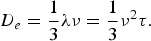
 describes the spatial electron–electron scattering. This holds for Eq. (2) analogous. D e accounts for the electron–electron scattering while D p describes the phonon–phonon scattering and is for both given by the relation

where λ denotes the mean free path and ν the mean velocity of the considered particle. Since only electronic stopping has to be considered here, the source term  only enters Eq. (1). The first step in computing the temperature distribution,
 is to calculate the electronic excitation induced by the ion. This specific process has been explained in detail (Osmani et al., Reference Osmani, Duvenbeck, Akcöltekin, Meyer, Lebius and Schleberger2008). Briefly, we employed the Lindhard model (Lindhard and Scharff, Reference Lindhard and Scharff1961) in combination with density functional theory (DFT) electronic density data. The time– and space–resolved electronic energy loss
 is used as a source for Eq. (1). Since the TTM makes use of the temperatures of the systems and the energy loss is given in energy units, one has to rewrite Eqs. (1) and (2) into an energy dependent form with the use of the specific heat capacity C p. Doing so a space– and time–dependent temperature distribution is acquired.
However, one must keep in mind that the aforementioned definitions have been derived for a free electron gas, while in the experiments insulators have been studied. The electrons in a non-excited insulator are bound to their atoms and therefore cannot participate in the heat conduction processes, which is assumed to be essential in order to explain the modifications. For this reason, the thermal properties of the target under irradiation have to be examined.
2.1. Electronic System
Once the primary particle penetrates the insulator surface, a cylindrical excitation zone with a diameter on the order of the ion diameter around the track core is generated—exciting electrons from the valence to the conduction band generating free carriers. These electrons are bound to their place where they were excited by Coulomb attraction to assure quasi neutrality in the insulator (Baranov et al., Reference Baranov, Martynenko, Tsepelevich and Yavlinski1988) but still are able to ionize atoms at the edge of the excitation area. By this process (electron-electron-ionization as well as phonon–phonon scattering) electronic energy is transported through the insulator bulk and may reach the surface.
In our calculations, excited electrons are treated as a diluted free electron gas. The excitation energy is transferred to the atomic system in terms of phononic excitation by electronic deexcitation. Hence, the higher the electronic energy density, the more phonons are created, thus, leading to an increased lattice temperature. In order to account for the inhomogeneous electron–electron scattering probability, temperature dependent diffusivity is used by introducing the scattering rate τ
Substituting

and

yields for the temperature–dependent electron diffusivity

with k B being the Boltzmann constant, m e begin the electron mass, T e begin the electronic and T p begin the phononic temperature. The parameter a = 9×10⁹(K 2s)−1 can be calculated from low temperature resistance measurements under negligence of electron–phonon scattering, while b is treated as a fitting parameter.
While bT p≪aT e2D e(T e,T p) in Eq. (7) is proportional to 1/T e thus the electronic excitation is confined to a small area until enough energy is transferred to the lattice via electron–phonon scattering; lowering the temperature of the electron and increasing its scattering probability.
As mentioned above, it is necessary to transform the excitation energy into a temperature. As a first approach, we assume that the electronic temperature can be calculated using E e = (γ/2)T e2 where γ, the heat capacity constant is given by
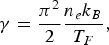
with T F = 2.67×10⁴ K the fermi temperature and n e = 5.6×1022 cm−3 the electronic density extracted from electronic density calculations performed in (Osmani et al., Reference Osmani, Duvenbeck, Akcöltekin, Meyer, Lebius and Schleberger2008).
This approach is reasonable since in Lin et al. (Reference Lin, Zhigilei and Celli2008), it was shown that Eq. (8) is valid even for high electronic temperatures as it is in our case.
2.2. Phononic System
While the penetrating ion interacts only with the electronic system, the lattice is heated locally inside the ion track core. Phonon–phonon scattering then transports the energy out of the excitation region and finally to the surface. This can be described by the lattice diffusivity

Since the amount of energy transferred to the lattice is controlled by g · (T e−T p) in Eq. (2), only a small fraction of the electronic energy is transferred at each numerical time step, and therefore the correct transformation into a temperature becomes crucial. For that purpose, we use specific heat capacity measurements from experiments at low (Itoh et al., Reference Itoh, Wang, Inaguma, Yamaguchi, Shan and Nakamura1999), and high (de Ligny & Richet, Reference de Ligny and Richet1996) temperatures.
The temperature-dependent heat conductivity is approximated by K = (αT p)−1 (Klemens, Reference Klemens1960) with a fitting parameter α, which will be studied below.
3. NUMERICAL APPROACH
For the numerical description, the crystal is discretized in elementary cell units with a lattice-constant a = 3.9051 Å in order to maintain the spatial resolution of the pre-calculated source terms. The calculations are carried out fully in three dimensional since the surface breaks the cylindrical symmetry commonly used. The two coupled differential Eqs. (1) and (2) are solved using finite difference method with von-Neumann boundary conditions at the surface.
In order to precisely describe the electronic excitation process, the numerical time steps are correlated with the passing time of the ion through each elementary cell. After the ion has left the simulation box, a constant time step of 0.1 fs is used.
3.1. Electronic Parameters
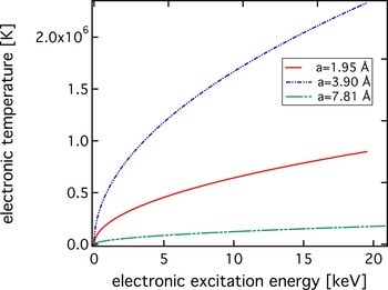
In this approach, the electronic temperature is determined within each numerical cell with a volume of one crystal elementary cell. According to Eq. (8), the number of particles per volume n e determines the heat capacity. Therefore, by changing the discretization, (i.e., the volume) the electronic temperature changes. This is shown in Figure 1 for three different discretizations Δx = a = 3.9051 Å (the calculated lattice parameter for SrTiO3), Δx = 2 · a, and Δx = 0.5 · a. The resulting temperature ranges from 105 K to 106 K. However, such high electronic temperatures are due to the very limited numbers of electrons, thus making this approach in the best case questionable. Similar temperatures are often observed in experiments by fitting a Fermi-Dirac distribution to the measured electronic energies (Schiwietz et al., Reference Schiwietz, Xiao, Grande, Luderer, Pazirandeh and Stettner1999). A rough approximation on the number of excited electrons, participating in Eq. (8), by ΔE/E gap leads to ≈104 electrons along the track core, i.e., cylinder with a length of 1 µm and a radius of 10 nm. Considering the density of excited electrons, it is obviously clear that the electrons are in a non-equilibrium state making it difficult to define an electronic temperature.
(Color online) Electronic temperature as a function of excitation energy for different cell discretization.

To study the effects of this volume-dependence in the electronic temperatures, calculations with constant and temperature dependent diffusivity were performed in both cases with an otherwise identical set of parameters.
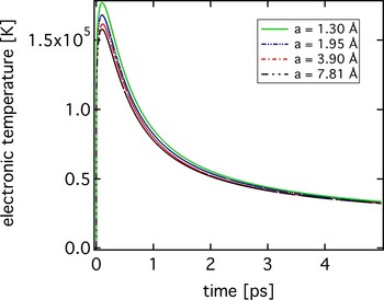
To mimic the experimental resolution the mean temperature on the area (≈30 nm2) of one observed nano-dot is determined. Figure 2 shows the electronic temperature evolution for different discretization volumes. The maximum temperature is decreasing with increasing Δx, while the observed deviation on the time constant τ (assuming an exponential decay) shows no dependence on the spatial discretizations.
(Color online) Electronic temperature evolution for different cell discretizations. The calculations are performed with a constant diffusivity.

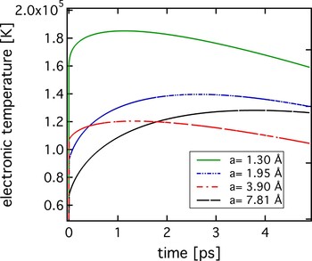
By introducing a temperature (and thereby a spatially) dependent diffusivity, the TTM becomes a non-linear system of differential equations and its solution is therefore not identical to the simple TTM. This can be seen in Figure 3. The solution is no longer an exponential function and strongly depends on the chosen spatial discretizations, which is unphysical.
(Color online) Electronic temperature evolution for different cell discretizations. The calculations are performed with a temperature dependent diffusivity.

It has been pointed out that a constant diffusivity is not able to explain the nano-dot formation (Akcöltekin et al., Reference Akcöltekin, Akcöltekin, Osmani, Duvenbeck, Lebius and Schleberger2008). There are two reasons: first that electronic excitation energy is transported too fast (within only a few femtosecond) away from the ion track core. While second a local melting process is impossible since the flux of energy between the electrons and the lattice is limited by the coupling parameter g.
However, with a temperature dependent diffusivity it is possible to describe the observed nano dot formations. In the following, the discretization volume has been chosen to match the experimental findings (distance between dots, periodicity, see Akcöltekin et al. (Reference Akcöltekin, Akcöltekin, Osmani, Duvenbeck, Lebius and Schleberger2008)) as 3.9051 Å.
3.2. Coupling Parameters
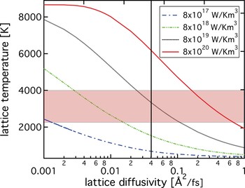
As explained in the model section, several parameters enter the equation, however, very little is known experimentally about the electron-phonon coupling parameter as well as the temperature dependent lattice diffusivity, and therefore, the parameters are treated as fitting parameters. In order to limit the parameters to physically reasonable values, calculations are performed with various coupling and diffusivity parameters and the results are checked for consistency with the experimentally observed structural surface modifications. In general, we assume that at least the melting temperature of SrTiO3 (T m = 2300 K) has to be reached in order to result in a permanent material modification such as a nano-dot. The actual temperature needed for the melting process is presumably higher due to the latent heat. Therefore, in the following we consider a temperature interval from 2300 K up to 4000 K as a criteria for the melting to occur.
In Figure 4, the maximum of the lattice temperature (heated by electron-phonon coupling) is shown for different lattice diffusivity D p and three different coupling constants g. The red rectangular (color online) indicates the reasonable temperature interval while the line shows the resulting maximal allowed diffusivity (see below). With an increasing electron-phonon coupling, the maximum of the lattice temperature increases as well.
(Color online) Lattice temperature as a function of lattice diffusivity for different electron-phonon coupling constants.

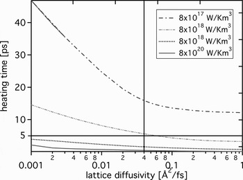
A coupling constant g < 8×10¹⁷ W/Km3 can be ruled out immediately because the resulting lattice temperature is below the melting temperature. To further limit the parameter range, the lattice parameter need to be studied in some detail. The limits of this parameter can be estimated from the time needed by the lattice to reach its maximum temperature. This is shown in Figure 5.
Heating time as a function of lattice diffusivity for different electron-phonon coupling constants.

Figure 5 mirrors the electron–phonon interaction time. Unfortunately, no experimental data on the electron–phonon interaction in insulators after MeV ion excitation is known. However, for the irradiation of metals with femtosecond laser-pulses, it is well known that the electron–phonon coupling time is on the order of a few ps (see reference 27 in Lorazo et al. (Reference Lorazo, Lewis and Meunier2006)). Since in the case of an insulator target, the number of free electrons is significantly lower, we can safely assume that the corresponding time will be even larger than these few petasecond. Under this constraint, coupling constant larger than 8×10¹⁹ W/Km3 is also not acceptable and with the exclusion discussed above only a coupling constant of g~1018 W/Km3 is valid. While this curve drops below the threshold of 5 ps for a lattice diffusivity larger than 0.04 Å2/fs we can draw another line to limit the lattice diffusivity.
The cross section of the rectangular with the line in Figure 4, limits the physically possible parameter combinations.
Note that in (Akcöltekin et al., 2008), the geometric relation l = d/tan θ was used to determine the electron–phonon-coupling g. In this model, I is the total chain length, θ the polar angle of incidence with respect to the surface and d a material specific parameter indicating the maximum depth of the ion at which significant structural modification can still be observed on the surface. By these means g has been determined to be ~1018 W/Km3, which is in good agreement with the range found in the present considerations.
4. CONCLUSION
In this paper, we discuss the effect of introducing a temperature dependent electronic diffusivity D e(T e,T p) into the TTM. This is done to implement physically correct timescales for the transfer of energy from the electronic to the phononic system. By this means, we are able to reproduce experimental findings such as nano-dot distance and periodicity as well as make predictions on the energy threshold for nano dot generation.
However, we observed a strong dependency of the solution of the modified TTM on the applied discretizations Δx, for which we chose the one reproducing the characteristics of the observed surface nano dot patterns best.
We used experimental findings (both laser and ion beam experiments) to limit the range of the electron-phonon-coupling parameter g and the lattice diffusivity D p. The coupling-parameter g has been determined to be on the order of 1018 W/Km3 while the lattice diffusivity was limited to D p ≤ 0.04 Å2/fs.
Further studies are needed, especially since the used model strongly depends on the assumption of a thermalized electron system. Furthermore it is necessary to have a deeper understanding of the relaxation process of non thermal electrons. One possible approach is the complete Boltzmann transport formalism, which is currently under consideration in our labs.
ACKNOWLEDGMENTS
The authors would like to acknowledge financial support from the Deutsche Forschungsgemeinschaft within the Sonderforschungsbereich 616 entitled Energy Dissipation at Surfaces, the Emmy Noether-Programm RE 1141/11-1 Ultrakurzzeit Dynamik laserangeregter Festkörper and the Research Center OPTIMAS. We thank Andreas Duvenbeck for numerous valuable discussions.