I. INTRODUCTION
Light metal hydrides such as LiAlH4 or NaAlH4 are currently extensively investigated for their possible application in hydrogen storage systems due to their high hydrogen content of 10.6 and 7.4 wt%, respectively. Among the challenges that still need to be overcome to introduce these materials into commercially available systems, hampered hydrogen desorption and reabsorption kinetics are probably the most pressing issue. Reference Andreasen, Vegge and Pedersen1,Reference Gao, Adelhelm, Verkuijlen, Rongeat, Herrich, Van Bentum, Gutfleisch, Kentgens, De Jong and De Jongh2 It has been proposed that confining light metal hydrides into micro- and mesoporous scaffolds can help to solve some of the current limitations. For that purpose, different lightweight carbon-based materials such as carbon nanotubes Reference Adelhelm and de Jongh3,Reference Baldé, Hereijgers, Bitter and de Jong4 or high surface area Reference Züttel, Wenger, Sudan, Mauron and Orimo5 graphite were used as well as microporous metal–organic frameworks. Reference Bhakta, Herberg, Jacobs, Highley, Behrens, Ockwig, Greathouse and Allendorf6,Reference Stavila, Bhakta, Alam, Majzoub and Allendorf7 Reducing the size of the active material down to several nanometers can dramatically alter its stability leading to vastly reduced activation energies for hydrogen desorption as well as enhanced desorption kinetics. Moreover, due to reduced mobility of the resulting decomposition products, phase separation and sintering occur less pronounced. Reference Orimo, Nakamori, Eliseo, Züttel and Jensen8–Reference Gao, Ngene, Lindemann, Gutfleisch, de Jong and de Jongh13 The result of these efforts is a notably improved homogeneity of the obtained composite materials.
Two general pathways exist for infiltrating light metal hydrides into micro- or mesoporous matrices. When using the melt infiltration technique the hydride is molten into the porous host after being heated under elevated hydrogen pressure. The latter is required to shift the chemical equilibrium toward the hydride and to prevent preliminary decomposition. Reference Adelhelm, Gao, Verkuijlen, Rongeat, Herrich, van Bentum, Gutfleisch, Kentgens, de Jong and de Jongh14 While this procedure is somewhat feasible for sodium aluminum hydride, lithium aluminum hydride is metastable at room temperature and would require an equilibrium pressure that is beyond the technological means available. Reference Felderhoff, Weidenthaler, von Helmolt and Eberle15 An alternative can be found in the solution impregnation procedure. Here the hydride is dissolved in a suitable solvent and then added to, e.g., the carbon compound. Followed by a drying step to evaporate the solvent, the impregnation step can be repeated several times to increase the loading. Lithium aluminum hydride decomposes in three steps according to the following equations:
 $${\rm{3LiAl}}{{\rm{H}}_{\rm{4}}} \to {\rm{L}}{{\rm{i}}_{\rm{3}}}{\rm{Al}}{{\rm{H}}_{\rm{6}}} + {\rm{2Al}} + {\rm{3}}{{\rm{H}}_{\rm{2}}}\quad ,$$
 $${\rm{2L}}{{\rm{i}}_{\rm{3}}}{\rm{Al}}{{\rm{H}}_{\rm{6}}} \to {\rm{6LiH}} + {\rm{2Al}} + {\rm{3}}{{\rm{H}}_{\rm{2}}}\quad ,$$
 $${\rm{2LiH}} + {\rm{2Al}} \to {\rm{2LiAl}} + {{\rm{H}}_{\rm{2}}}\quad .$$
Thus, by introducing lithium aluminum hydride into porous carbon such as CMK-3 and then desorbing the hydrogen entirely should allow for the formation of highly homogeneous aluminum metal–carbon composites. These composites are currently of great interest, e.g., for applications in lithium ion batteries. Reference Lei and Ma16–Reference Chandrasoma, Grant, Bruce and Bruce18 However, as already reported in earlier studies on the direct synthesis of complex metal hydrides by Ashby et al., Reference Ashby, Brendel and Redman19,Reference Ashby, Dobbs and Hopkins20 it is rather difficult if not entirely impossible to remove the last traces of tetrahydrofuran (THF) once in contact with LiAlH4. Nevertheless, more recent investigations showed the importance of THF as an adduct to LiAlH4, which dramatically improves the thermodynamics of both hydrogen desorption and reabsorption. Wang et al. Reference Wang, Ebner and Ritter21 pointed out that the regeneration of LiAlH4 in the presence of THF as an adduct to the hydride was about seven times more effective compared with experiments without THF. In contrast, there exist no reports on the fabrication of oxidic compounds by using light metal hydrides in THF.
Therefore, this study focuses on tetrahydrofuran as it is one of the most commonly used solvents for light metal hydrides and its effect on the decomposition of LiAlH4 when confined in mesoporous carbon CMK-3. A comprehensive investigation of both the desorption process as well as the resulting final compounds using solid-state magic angle spinning nuclear magnetic resonance (MAS-NMR), depth profile auger electron spectroscopy, and x-ray photoelectron spectroscopy is presented.
II. METHODS
A. Preparation procedure
All materials were used and stored under argon inert gas atmosphere in a glove box with water and oxygen levels below 3 ppm at all times. The borosilicate glassware used for handling the hydrides was dried under vacuum at 373 K for 24 h to remove traces of water adsorbed to the surface. Quartz glassware was dried at 1073 K. Mesoporous carbon CMK-3 was prepared according to a procedure described elsewhere. Reference Jun, Joo, Ryoo, Kruk, Jaroniec, Liu, Ohsuna and Terasaki22 Prior to the impregnation process, it was heated to 873 K under 0.9 bar hydrogen over pressure to reduce any oxidizing surface functionalities, which might react with the hydride. A two molar solution of LiAlH4 (LAH) in THF was obtained from Sigma-Aldrich and used without further purification. For a typical impregnation, 100 mg CMK-3 was used together with 80 μL LiAlH4 solution. The evaporation of THF was performed at 373 K under vacuum for at least 3 h. This impregnation procedure was repeated several times with stepwise reduced amounts of solution until the carbon material was loaded with ∼17 wt% LiAlH4, hereby denoted as “LAH@CMK-3.” In accordance with the results obtained by nitrogen physisorption experiments, the amount of solution added never exceeded the available inner pore volume of CMK-3, thus ensuring that no hydride recrystallized outside of the carbon pore system. LAH@CMK-3 was then heated under dynamic vacuum with a heating rate of 1 K/min up to 673 K and subsequent holding at this temperature for 23 h. Afterward, the material was cooled naturally. The resulting compound is referred to as “LA@CMK-3.”
For x-ray powder diffraction (XRD) experiments, powder samples were fixed as a thin layer on an acetate film. Data were collected in flat sample transmission mode on a STOE STADI P powder diffractometer equipped with a 6°-position sensitive detector (PSD) and a Ge(111)-monochromator. The samples were measured with Cu K α1-radiation with a step size of Δ2θ = 0.01°.
B. Nitrogen physisorption experiments
The nitrogen sorption experiments were carried out using a Quantachrome Quadrasorb SI apparatus. Prior to the measurement, the samples were degassed under dynamic vacuum at 393 K for 24 h. Specific surface areas were calculated at a relative pressure p/p 0 = 0.3 using the single-point Brunauer–Emmett–Teller (BET) method according to the BET theory. The total pore volume was determined at p/p 0 = 0.9. The pore size distributions were obtained using the Quenched Solid Density Functional Theory (QSDFT) equilibrium model implemented in the Quadrawin 5.05 software by Quantachrome assuming a cylindrical pore geometry which in agreement with the actual pore geometry of the CMK-3.
C. MAS-NMR experiments
Solid-state MAS-NMR spectra were obtained using a Bruker Avance 400 MHz spectrometer with a wide bore 9.4 T magnet and a Bruker 4 mm CP-MAS probe. The spectral frequency was 104.27 MHz for the 27Al{1H} nucleus. The NMR chemical shifts are reported in parts per million (ppm) externally referenced to 1.0 M Al(NO3)3 aqueous solution. The material was packed into a 4 mm ZrO2 rotor in an argon-filled glovebox and was sealed with a tight fitting Kel-F cap. Sample spinning of 10 kHz was chosen and it was performed using dry nitrogen gas. The one-dimensional 27Al{1H} MAS-NMR spectrum was acquired after a 4 μs single π/2 pulse (corresponding to a radiofield strength of 62.5 kHz) with application of a strong 1H signal decoupling by using the two-pulse phase modulation (TPPM) scheme. Spectra were acquired at 20 °C controlled by a BRUKER BCU unit.
D. Thermoanalysis coupled with mass spectrometry
Simultaneous TG and mass spectrometry analysis (DTA-MS) was carried out in a Sensys Evo (Setaram) placed inside an argon-filled glovebox. The measurements were carried out using a 1 bar argon flow with a heating rate of 1 K/min. The TG-DSC system was coupled to a mass spectrometer from Pfeiffer Vacuum (Omnistar GSD 320 O1) located outside the glovebox via a heated stainless steel capillary (1 m, 423 K). The mass spectrometer uses an yttriated iridium filament and a QMG 220 quadrupole. The collected masses were monitored with the integrated C-SEM detector.
E. Depth profiling auger electron spectroscopy (DP-AES)
A JEOL JAMP-9500 F field emission auger microprobe with primary electrons of 10 keV at an electron current of 10 nA was used to conduct AES measurements and to obtain scanning electron micrographs (SEM). For depth profiling, the sample surfaces were sputtered by a scanned beam of 1.5 keV Ar+-ions at an incident angle of about 30°. Spectra were recorded after intervals of 0.3 min. The corresponding sputter rate calibrated to silicon dioxide was determined to be 1.4 nm for each cycle. The quantification of element concentration was performed by using the differentiated signals and the standard single element sensitivity factors.
F. X-ray photoelectron spectroscopy
The XPS measurements were carried out on a PHI 5600 CI (Physical Electronics) spectrometer equipped with a hemispherical analyzer operated at a typical pass energy of 29 eV and with an analysis area of 800 μm in diameter. Mg Kα excitation (350 W) was used without applying an additional energy electron charge neutralizer. To avoid any contact of the samples with air and moisture, a transfer chamber (Physical Electronics) was used for the sample transport from the argon-filled glove box to the XP spectrometer. All spectra were calibrated with respect to sp2-hybridized carbon at 285 eV. More details on the experimental procedures can be found in previous works. Reference Pinkert, Giebeler, Herklotz, Oswald, Thomas, Meier, Borchardt, Kaskel, Ehrenberg and Eckert23–Reference Oswald, Nikolowski and Ehrenberg25
III. RESULTS AND DISCUSSION
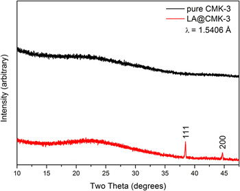
Figure 1 shows the x-ray patterns of both pure mesoporous carbon CMK-3 as well as LA@CMK-3 after the infiltration–desorption process described above. The pattern of LA@CMK-3 exhibits two reflections which are ascribed to metallic aluminum. Considering the narrow pore size of the carbon host (radii around 20 Å, see Fig. 2) as well as the sharp nature of those reflections, it is reasonable to assume that the aluminum phase is located on the outer surface of the carbon particles rather than inside the pore system. In the latter case, the aluminum would be expected to be nanocrystalline or even amorphous yielding much more broadened reflections in XRD. Such formation of a separate phase of pristine aluminum upon desorption of light metal hydrides confined in micro- or mesoporous carbon scaffolds is a commonly observed effect being characteristic for this particular combination of materials. Reference Himakumar, Viswanathan and Srinivasamurthy26,Reference Graetz, Wegrzyn and Reilly27 Within the detection limit of XRD, no long-range ordered hydride is observed.
X-ray diffraction patterns of pure CMK-3 (black) and the final composite material LA@CMK-3 (red). Reflections from Al metal are marked by the corresponding hkl indices.

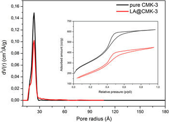
Pore size distributions of CMK-3 (black) and LA@CMK-3 (red) obtained by QSDFT-Method. The inset shows the respective N2 physisorption isotherms.

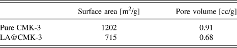
Furthermore, nitrogen physisorption experiments were carried out to supplementarily demonstrate a successful infiltration process. Figure 2 shows the adsorption isotherms of pure CMK-3 and LA@CMK-3 and also the respective pore size distributions obtained by QSDFT calculations assuming cylindrical pore geometry. The initial pristine CMK-3 infiltrated sample exhibits a much reduced capacity for nitrogen uptake. Also, while the pore size of the carbon matrix itself is virtually unchanged, the quantity of accessible pores is notably reduced. Additionally, the total surface area and total pore volume decrease by 40 and 25%, respectively, as summarized in Table I, which indicates a partial filling of the pore system.
BET surface areas and pore volumes of pure CMK-3 and LA@CMK-3.

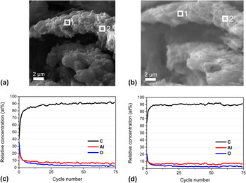
To further confirm the homogeneous filling of the porous matrix for LA@CMK-3, DP-AES was applied. By definite sputtering through the nanocomposite particle, the inner chemical composition is accessible for AES analysis. Figure 3(a) shows scanning electron micrographs of the as-synthesized nanocomposite. Figure 3(b) shows the SEM image of the nanocomposite after 75 sputter cycles to verify material stripping. The calculated depth profiles in relation to the number of sputtered cycles are depicted in Figs. 3(c) and 3(d). The two marked areas in Figs. 3(a) and 3(b) were analyzed by AES before the measurement [cycle no. 0, Figs. 3(c) and 3(d), bottom] and after each sputter cycle [cycle number 1-75, Figs. 3(c) and 3(d), bottom] to obtain information on the homogeneous distribution of LA@CMK-3. All three depth profiles show very similar characteristics revealing the very homogeneous structure of the final composite, thereby proving that the chosen impregnation route is suitable and yields the desired homogenous material. Carbon is present as the main element, followed by aluminum and interestingly, also nonnegligible amounts of oxygen, which seems to trail the aluminum concentration profile. The detection of constantly present and homogenously distributed oxygen throughout the final composite material is surprising since the decomposition of the LiAlH4 precursor according to Eqs. (1)–(3) is not expected to yield any form of an oxygen-containing compound.
SEM images before (a) and after (b) auger electron spectroscopy experiments of LA@CMK-3. Depth profiles (c and d) were obtained at the positions 1 and 2, respectively.

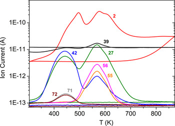
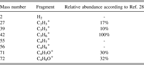
An indication of an unusual decomposition of the THF solvent molecules attached to the lithium aluminum hydride is provided by the curves obtained from the thermoanalysis (DTA-MS) shown in Fig. 4. Here, the mass and the respective amounts of fragments evolving from the sample during heating are given. This technique allows for in situ monitoring of both the desorption process and also the respective evolving gaseous species. Table II lists the measured mass numbers and the corresponding fragments. Reference Dampc, Szymańska, Mielewska and Zubek28 The heat treatment of the sample was conducted under argon atmosphere with a heating rate of 1 K/min. Two major stages of decomposition are visible in the graph of Fig. 4. The first step reaches peak intensities of ion current for the mass numbers 27, 39, 42, 71, and 72 at around 400 K and 500 K for m/z 2. A second step is observed with m/z of 27, 39, 42, and 2, but this time without 71, 72 but instead 55 and 56 at around 570 K. This difference in the relative amounts of fragments that are detected at the respective temperatures clearly indicates that the products evolving from each stage are resulting from different types of decomposition reactions. Even more notably, these results differ significantly from the fragmentation processes of pure THF. Reference Dampc, Szymańska, Mielewska and Zubek28 As described in the experimental section, each impregnation step of CMK-3 was followed by a drying step at 373 K under vacuum to remove excess solvent. Hence, taking into account the small size of the resulting LiAlH4, which leads to the overall downward shift of the respective desorption temperatures for each step, it can be assumed that the reaction described in Eq. (1) already took place during the preparation of LAH@CMK-3. This explains the observation of only two maxima during the desorption process. However, it is interesting to note that the mass numbers 71 and 72 corresponding to the “intact” THF molecule and a THF molecule without one α-H atoms do not appear in the second stage of fragments. Reference Dampc, Szymańska, Mielewska and Zubek28,Reference Mayer, Guest, Cooper, Shpinkova, Rennie, Holland and Shaw29 Those fragments in the first stage result from solvent molecules which were not coordinated to the hydride. It can be concluded that after surpassing the threshold of approximately 523 K, those remaining coordinated THF molecules are not able to evaporate without substantial bond cleavage and consequently leave oxygen atoms attached to aluminum. It is also a matter of fact that metallic aluminum is highly attractive for absorption and bonding of oxygen. At this point, it is therefore crucial to determine whether or not the detected oxygen is in fact bound to the aluminum.
DTA-MS curves including the mass numbers of the respective fragments evolving during the heat treatment of LAH@CMK-3. See also Table II for more details.

Mass numbers and the respective fragments corresponding to Fig. 4.

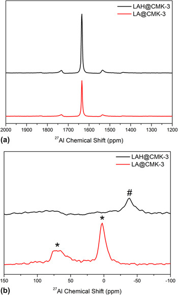
For that reason, solid state MAS-NMR spectroscopy was performed to gain additional information on the composition of the newly formed compounds located inside the pores of the host matrix. Figure 5 represents two regions of 27Al NMR spectra of the as-infiltrated sample LAH@CMK-3 (black line) as well as the final composite material LA@CMK-3 (red line). In Fig. 5(a), the signals centered at 1640 ppm belong to pure aluminum metal. This further supports the findings from XRD experiments, which also evidenced a fraction of pure aluminum being located outside of the CMK-3 carbon matrix. Lower chemical shifts of the 27Al-NMR-spectra of the same samples are shown in Fig. 5(b). LAH@CMK-3 exhibits a broadened signal (#) between −25 and −50 ppm that corresponds to the hexahydride species Li3AlH6, which is the result of the first decomposition stage of LiAlH4 according to Eq. 1. Reference Choi, Lu, Sohn, Fang, Kim, Bowman and Hwang30 Hence, the detection of this hexahydride phase additionally confirms the results of the DTA-MS experiments discussed above, in which only two maxima of hydrogen concentration were observed, indicating that the first hydrogen desorption step from LiAlH4 already took place during the infiltration step. For LA@CMK-3, two signals are located between 40–80 ppm and 0–10 ppm corresponding to aluminum–oxygen bonds with the distinction of both tetrahedral and also octahedral aluminum oxide sites being present. Reference Choi, Lu, Sohn, Fang, Kim, Bowman and Hwang30,Reference Verkuijlen, Gelder, Van Bentum and Kentgens31 This finding is concurrent with earlier reports that studied the oxidation products of NaAlH4. First, a highly disordered aluminum oxide/hydroxide is formed in which the aluminum is coordinated tetrahedrally by the oxygen atoms. This compound can then later be transformed into a more ordered aluminum oxide where oxygen coordinates aluminum octahedrally. Reference Verkuijlen, Gelder, Van Bentum and Kentgens31 However in our case, we clearly observe the NMR signals for both of these compounds. The fact that the line shape of the MAS NMR signals at low chemical shifts in Fig. 5(b) of the 27Al-nuclei is broadened to this extent clearly suggests that the respective aluminum-containing compounds exhibit a high degree of structural disorder, thus being either nanocrystalline or even amorphous. This is expected since those compounds are prevented from establishing a long-range order due to the spatial confinement at the nanometer scale imposed by the CMK-3 carbon matrix. Reference Herberg, Maxwell and Majzoub32,Reference Majzoub, Herberg, Stumpf, Spangler and Maxwell33
MAS-NMR spectra of the 27Al{1H} experiments of LAH@CMK-3 (black) and LA@CMK-3 (red) revealing the presence of different aluminum species. (a) Signals of bulk aluminum centered at ∼1640 ppm including sidebands. (b) Evidence for Li3AlH6 phase (#) in LAH@CMK-3 and aluminum oxides (*). Positions between ∼40–80 ppm correspond to tetrahedral Al oxide sites, whereas those at ∼0–10 ppm belong to octahedral Al oxide sites Reference Verkuijlen, Gelder, Van Bentum and Kentgens31 . All signals are significantly broadened indicating the nanocrystalline or amorphous nature of the respective material.

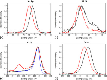
The assessment that indeed oxidic compounds result from the reaction of LiAlH4 with the THF molecules is additionally supported by the results of the XPS investigations that are discussed as follows. Figure 6 shows the XP spectra of the infiltrated material as well as the final composite LA@CMK-3. For comparative reasons, also the C1s spectrum [Fig. 6(c)] of the pure untreated CMK-3 was added. It is clearly evident that the overall tendency is a strong shift toward higher binding energies of aluminum, oxygen, and a little less pronounced also for lithium when comparing the infiltrated sample with the desorbed one. The Al 2p peak [Fig. 6(a)] of LAH@CMK-3 is centered at 74.7 eV and the Li 1s signal is located mainly around 56.2 eV, which is consistent with values reported for pristine lithium alanate. Reference Moulder, Stickle, Sobol and Bomben34,Reference Amama, Grant, Shamberger, Voevodin and Fisher35 Moreover, the O 1s peak [Fig. 6(d)] measured at 531.7 eV is at the expected position for molecules containing ether groups. Reference Lopez, Castner and Ratner36 Please note that the signals in the C 1s spectrum at 285 eV, which are attributed to the sp2-hybridized carbon of the graphitic parts of the CMK-3, only marginally increase in width throughout the entire process, which likely happens due to local charging effects during the XPS measurement. Nevertheless, the consistency of that signal also points out that the structure of the CMK-3 host remains intact during the entire process of infiltration and desorption. After the heat treatment of LAH@CMK-3, both the Al 2p peak as well as the O 1s signal are shifted toward higher binding energies of 75.7 and 532.8 eV, respectively. This finding provides clear evidence that in fact aluminum oxides are among the final reaction products that evolve from the decomposition of the LiAlH4 – THF species. In comparison to that, the Li 1s signal [Fig. 6(b)] only shifts to about 56.8 eV suggesting that the change in binding state for lithium overall is less severe than for the other elements. More notably, the C 1s XP spectrum of the final composite material features a second peak arising at 291.7 eV, which most likely accompanies the formation of a carbonate species or a similar organic residue, as reported by Andersson et al. Reference Moulder, Stickle, Sobol and Bomben34,Reference Kanamura, Tamura and Takehara37,Reference Andersson, Henningson, Siegbahn, Jansson and Edström38 A binding energy that is high, basically rules out the presence of any other carbon compound than might emerge considering the elements present in the sample.
XP spectra of pure CMK-3 (blue), LAH@CMK-3 (black), and LA@CMK-3 (red) showing the overall shift of binding energies toward more oxidic states.

Concluding from the afore discussed data, it is clearly evident that THF solvent molecules attached to LiAlH4 can indeed irreversibly oxidize the hydride at elevated temperatures mainly forming nanosized aluminum oxides and probably also carbonates inside the carbon host. Revealing the detailed mechanism of this unexpected behavior is beyond the scope of this report. However, it shall be noted that the results presented here are in good agreement with previous findings. The destabilization of etheral solvents by lithium compounds is widely known as well as the possibility of THF attaching to aluminum surfaces via its oxygen atom after undergoing a ring-opening reaction. Reference Clayden and Yasin39,Reference Wang and Ross40 A detailed mechanism for the decomposition of THF is proposed in the supporting information (Scheme S1, ESI). Lacina et al. Reference Lacina, Yang, Chopra, Muckerman, Chabal and Graetz41 pointed out that it is energetically most favorable for LiAlH4 in solution to coordinate three THF molecules forming contact ion pairs at room temperature. It is assumed that the ability of different solvents to form adducts with the alanate is crucial for its successful regeneration. Reference Wang, Ebner and Ritter21,Reference Graetz, Wegrzyn and Reilly27,Reference Bikiel, Di Salvo, González Lebrero, Doctorovich and Estrin42 To our understanding of the case presented here, the last hydrogen desorption step of LiAlH4 [Eq. (3)] is crucial for the formation of nanosized aluminum oxides that are confined in the pores of the CMK-3 carbon host.
IV. CONCLUSIONS
It was shown that it is possible to homogeneously infiltrate the lightweight hydride LiAlH4 into the pore system of ordered mesoporous carbon CMK-3 via a multistep solution impregnation procedure. Analyzing the decomposition behavior of the infiltrated hydride as well as the resulting nanocomposite structure, we revealed an unexpected oxidation behavior of the THF solvent on the confined LiAlH4. Nanoscale aluminum oxides were formed possibly along with carbonate species as a byproduct at temperatures up to 673 K. A reduction of the onset temperature at which hydrogen desorbs from the hydride is achieved by introducing it into the carbon scaffold, consistent with previous studies on complex light metal hydrides confined in mesoporous scaffolds. The presented findings offer an interesting new way toward the targeted formation of carbon-supported nanosized aluminum oxides, which might be promising, e.g., for applications in catalysis. Reference Maity, Flores, Ancheyta and Fukuyama43–Reference Hao, Zhao, Yang, Liu and Liu45 In addition, we demonstrated the benefits of the combined use of multiple state-of-the-art techniques for analyzing the composite materials to gain a comprehensive picture of the structural features of these materials.
NOTES
The authors declare no competing financial interest.
Supplementary Material
Supplementary materials can be viewed in this issue of the Journal of Materials Research by visiting http://journals.cambridge.org/jmr.
ACKNOWLEDGMENTS
The authors are indebted to the EU (ERSF) and the Free State of Saxony (SAB Grant No. 14227/2337) within the ADDE—Functional structure design of new high performance materials via atomic design and defect engineering (Grant No. 14227/2337) and the European Center for Emerging Materials and Processes Dresden (ECEMP) excellence clusters B1 and D2 (SAB Grant Nos. 100112628 and 100111670) for financial support. The German Federal Ministry of Education and Research (BMBF) is acknowledged for financial support (Grant No. 03KP801) for the JEOL JAMP-9500F auger electron spectrometer. The authors furthermore thank U. Georgi and R.R. Rottenkügler for fruitful discussions.