1. INTRODUCTION
Oil was first commercially exploited in the North Sea in the 1960s. The exploitation has been underpinned by regular, reliable helicopter operations enabling the movement of staff and equipment to and from the shore. The North Sea environment is challenging for rotorcraft operations from many perspectives, not least its remoteness from the shore, the exacting weather conditions and the changeable nature of rigs (location, obstacles, etc.). There have been six fatal accidents since 1976, with the loss of 79 lives. The worst was in 1986, when 45 people died in a Chinook helicopter crash. The root causes include amongst other things lightning strikes and collisions with rigs.
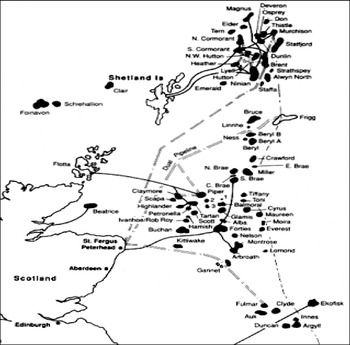
There are more than 300 helidecks in the UK sector alone being serviced by regular flights. (See Figure 1.) Approach options in Instrument Meteorological Conditions (IMC) are limited to using the aircrafts' weather radar to identify the rig. This radar is neither designed nor certified for the task and following a UK CAA review of helicopter human factors, in relation to in-service incidents reported, the need for an accurate and reliable instrument approach aid for conducting offshore approaches has been highlighted.
Overview of North Sea oil fields in UK sector.

This paper presents a summary of the results and recommendations of a number of tasks related to a feasibility assessment of EGNOS for North Sea helicopters undertaken within the auspices of the GIANT (GNSS Introduction in the AviatioN secTor) programme. The activities were aimed at the development and validation of an EGNOS-based approach for helicopters operating to the oil platforms in the North Sea. It involved the development of an EGNOS approach procedure, validation of the procedure through flight simulations, data collection on helicopters to validate technical feasibility as well as safety assessments of the proposed procedure.
2. NORTH SEA OPERATIONS
The North Sea – particularly at the latitudes of the oil fields – can be an inhospitable environment. A helicopter operating to the rigs is exposed to the full wrath of the weather with winds gusting in excess of 60 knots with no protection afforded by terrain. During winter lightning strikes to helicopters are common (and evidence suggests they appear to be induced by the aircraft themselves) due to passing thunderstorms. There is also hail and sleet to contend with along with icing conditions at the operating flight levels. Airflows around a rig superstructure can cause turbulence as well as up and down drafts. Furthermore the helipads are often located hundreds of feet above sea level. This means that a cloud base of down to 200′ may place the pad in cloud.
Even without the weather there are still many factors for the flight crew to contend with that are of particular significance once operating in IMC on an instrument approach. Whilst many oil platforms are fixed in their location a number of rigs are moveable and can be relocated at short notice. Some platforms are semi-submersible – tethered to the seabed but still free to heave on a heavy swell. Rigs often have moving cranes, gantries and chimneys that are used in ‘flaring’ – burning natural gas. Perhaps most hazardous for a crew on an instrument approach is the potential risk of encountering moving obstacles. It is not unheard of for supply vessels to arrive at the rig whilst the aircraft is on approach. As many of these ships are relatively large their superstructure can easily impinge on the planned flight path.
Despite all of these factors the vast majority of approaches are conducted successfully – even those in IMC at night. This is testimony to the skill and training of the current flight crews. The current instrument approach procedures to helidecks of North Sea oil rigs utilise the aircrafts' weather radar – an instrument that is neither designed nor certified for the task. They are known as Airborne Radar Approaches (ARA). The helicopter initially navigates to the proximity of the rig and then identifies the rig using the weather radar display and flies toward it descending on the altimeter at the same time. When closing on the rig the crew will level off and adopt an offset heading (typically 10°) to guide them abeam the rig whilst still maintaining radar contact. If by the closest point on this approach (typically 0·75NM) the crew have not achieved visual contact with the rig they will instigate a banking, climbing missed approach. In addition to being used for navigation the weather radar is used continually to look for other mobile obstacles in the final approach such as supply ships.
Flying the offset to the rig.

3. EGNOS IN THE NORTH SEA ENVIRONMENT
With so many rigs being serviced by regular flights, there is interest in improving today's instrument approach technology and the European Geostationary Navigation Overly Service (EGNOS) presents itself as a potentially attractive solution. EGNOS provides accuracy and integrity sufficient to enable guided vertical descent procedures and its ability to contain the navigation system error (NSE) could also permit closer approaches to the rigs to remove the necessity for a climbing, turning missed approach procedure. EGNOS could also maintain cost effectiveness as it requires no ground infrastructure on rigs (such as data links, etc). Removal of the traditional procedures using radar equipment not intended for the task, together with the ability to auto-pilot couple the EGNOS guidance to aid workload could all help to improve achieved safety levels and perhaps even operating minima in the future.
However, current aviation EGNOS equipment, standards and procedures are all oriented at approach operations for fixed wing aircraft into conventional airfields. Even those helicopter procedures currently available with GPS/SBAS known as Point-in-Space (PinS) approaches are entirely unsuitable for the offshore environment. Furthermore, the majority of platforms are located in the latitude range of 58°N to 63°N. At these latitudes the EGNOS geostationary satellites are at a low elevation angle (approx 20–25°) and are clustered in the sky to the south. This factor coupled with the often sub-optimal GPS antenna installations common on rotorcraft result in a major challenge to the successful application of EGNOS in this environment.
4. SBAS OFFSHORE APPROACH PROCEDURES
4.1. Requirements
An ideal offshore approach procedure would have a number of features which current satellite-based augmentation system (SBAS) technologies may or may not be capable of supporting. Ideally the approach would be straight in, but offset from the rig (as opposed to direct at the rig with a final abeam leg). This would facilitate a straight-ahead climb for a missed approach procedure rather than the current sub-optimal climbing turn. The approach should bring the helicopter abeam the rig at a point close enough to enable visual identification in IMC whilst also far enough away to allow for final speed and height adjustments. (See Figure 2.) SBAS should be well suited to providing this capability as the guidance is to waypoints rather than to the rig.
One of the benefits of the current ARA approach procedure is that it provides the crew with the ability to choose their approach heading. This is useful as the crew can select to optimise their approach taking into account wind direction and maintaining clearance from moving obstacles or superstructure. In addition the procedure is not constrained by an absolute rig location. Hence if the rig has moved the procedure can still be flown – it is navigation relative to the rig. It would be preferable if this ability was provided in an SBAS approach. In such a case there would be a need for:
• Flight crew selection of the destination rig (if the rig has moved this will necessitate the manual input of an accurate rig location)
• Flight crew selection of a preferred final approach track alignment to account for the wind heading
• SBAS avionics to generate an approach procedure to the destination rig that takes into account:
∘ The preferred approach track
∘ The necessity for a straight-ahead missed approach
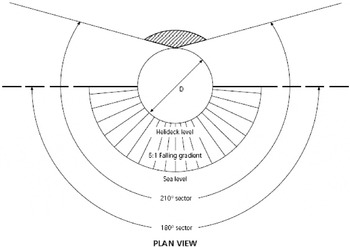
∘ The need to deliver the helicopter safely to a point at which it will be able to operate within the rig Obstacle Free Sectors (OFS) – the area out to 1km from the helipad guaranteed to be clear of fixed obstacles (see Figure 3) – without undue manoeuvring.
Plan view of example OFS.

This is a challenging requirement for current SBAS equipment as SBAS approaches consist of a set of waypoints that are typically hard coded in a database. These waypoints establish the track direction for the approach procedure. Furthermore, even if the procedure could be coded to give approach heading flexibility the issue of a rig having moved still remains. Where GNSS procedures have already been implemented in the Norwegian sector of the North Sea some of these constraints have been recognised. As a result, procedures have been coded only to fixed platforms and a set of up to four approaches per rig have been developed to allow for wind angle variation. This still results in a large database of waypoints just to serve a small number of rigs. However, it may represent the only pragmatic solution currently permitted by the technology.
New approach procedures should be able to provide guidance to the aircraft autopilot (where available). This will help to reduce overall cockpit workload during the critical approach phase of flight and allow the crew to focus on just monitoring the guidance whilst undertaking other tasks. Ideally the procedure should also provide guidance for the descent too that will encompass a stable descent (typically 4° to 6°).
The potential for mobile obstacles will remain a reality of North Sea operations. Therefore a new procedure will still need to provide the crew with the ability to ensure that the path ahead of them remains clear of obstacles. It is likely therefore that the need will remain for the use of the weather radar even on an SBAS approach.
4.2. SOAP Trial Procedure
Part of the work performed by the GIANT project was to design and test a new helicopter offshore oilrig approach procedure that used EGNOS to address the recognised shortcomings of those currently used in the North Sea. The result of this work is the SBAS Offshore Approach Procedure (SOAP). As shown in Figure 4, the approach is divided into four segments. The arrival segment is used to establish the target location and for the helicopter to descend to the minimum safe altitude of 1500ft. Once the helicopter reaches the Initial Approach Fix (IAF) it enters the initial approach segment, in which it aligns itself on the final approach heading and decelerates to the final approach speed between 60kts and 80kts – depending on the environment and the capabilities of the helicopter. During this time the crew will use the weather radar to check the system-generated final approach and missed approach areas and verify that they are clear of radar returns.
SBAS Offshore Approach Procedure.

On reaching the Final Approach Fix (FAF), the helicopter enters the final approach segment and begins its descent to the Minimum Descent Height (MDH, defined as the height of the rig's helideck plus 50ft, with a minimum value of 200ft in daylight and 300ft at night). The descent angle can vary depending on the elected final approach speed. Once the helicopter reaches the MDH, it flies a level segment during which the pilot and co-pilot attempt to acquire visual contact with the rig. If visual contact is not made, the helicopter will reach the Missed Approach Point (MAP) and perform a missed approach procedure simply by climbing straight ahead at the steepest safe angle.
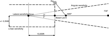
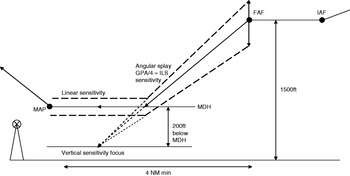
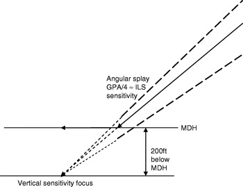
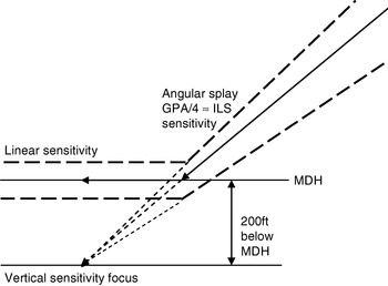
The various lengths and angles of the approach procedure can be seen in Figure 4. Certain points, such as the FAF, are positioned depending on distances that will vary, such as the distance covered whilst the helicopter is descending (which depends on the descent angle and the MDH value). The procedure also dictates the sensitivity of the guidance to be used, which can be seen in Figure 5, which shows lateral sensitivity, and Figure 6, showing vertical sensitivity.
SOAP Lateral Sensitivity.

SOAP Vertical Sensitivity.

Throughout the procedure, lateral guidance is provided by EGNOS. Vertical guidance during the arrival and initial approach segments is provided by the helicopter's baro-altimeter, and by EGNOS backed up by the radar altimeter during the final approach segment. The procedure has many advantages over the currently used procedure, as it is far less reliant on the non-certified weather radar, and establishes a final approach track that takes the helicopter past the rig at a safe distance without having to make a turn if a missed approach is performed.
4.3. Flight Simulation of SOAP
As part of the design process for the SOAP approach, a set of simulation trials were carried out in order to determine the optimum values of certain parameters in the procedure description and evaluate its overall flyability. These trials were carried out in the Eurocopter SPHERE facility, in Marignane, France. The pilots involved were representatives from various different members of the GIANT consortium, including the UK CAA, Bond Offshore Helicopters, CHC Scotia Helicopters, and Bristow Group Inc.
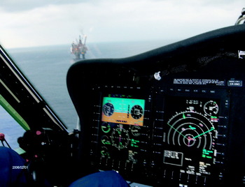
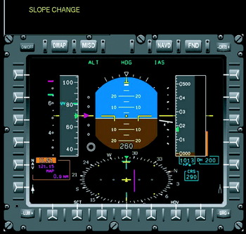
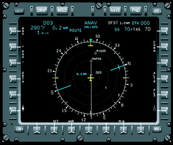
The SOAP procedure was flown in the simulator using different values for the Minimum Decision Range (MDR), descent slope, maximum offset angle between the final approach track and the track from MAP to rig, and final horizontal and vertical airspeeds. These were tested against different wind directions and speeds, and a visual range slightly above the MDR value. Also tested was the distance displayed to the pilot on the flight display, whether it be the distance to the MAP or to the helideck. Figures 7 and 8 show the primary flight display and navigational display as they were used in the simulations.
SOAP Primary Flight Display.

SOAP Navigation Display.

The primary results from the simulation trials were that the final visual approach and deceleration towards the rig is the most critical part of the procedure, and must be at least 0·75NM for a final groundspeed of 80kts, but could be reduced to 0·5NM for a groundspeed of 60kts. It was unanimously agreed by the test pilots that the primary flight display should indicate the distance to the MAP, rather than the helideck, as the latter was of little interest for navigation purposes and would be known by the pilot anyway. It was agreed that a glideslope of 6° was too steep at a groundspeed of 80kts, and that at this speed 4° should be the maximum. A maximum offset angle of 30° was agreed, with 45° making it hard to establish visual contact in the difficult visual conditions. A level segment length of 0·75NM was found to be adequate under all conditions and it was even found to be long enough to allow the helicopter to decelerate from 80 to 60kts if required. If situations demanded, it would also be acceptable for the level segment to be reduced to 0·5NM.
Also tested was the presentation of the vertical guidance provided to the pilot. Some pilots preferred the ‘procedural guidance’ (Figure 9) in which an ILS-like glideslope beam was provided during the descent but not during the level segment, whereas others preferred the ‘Full ILS-like guidance’ (Figure 10) in which a linear vertical deviation scale was provided on the level segment in addition to the ILS-glideslope. It was agreed by all trial participants that the ‘procedural guidance’ was adequate if AFCS was fully operative.
Example ‘procedural guidance’.

Example ‘Full ILS-like guidance’.

Overall the trials were deemed to be successful and of sufficient quality that the results were used to finalise the approach procedure as described above.
5. SAFETY ANALYSIS
An element of the GIANT project helicopter activities has been the development of a safety assessment for the proposed SOAP procedure. The assessment method used in this study employed an approach that has become familiar to the North Sea operators through previous studies commissioned from Helios by the UK CAA and presented at the Helicopter Safety Research Management Committee (HSRMC). It involves two phases, one in which a ‘failure case’ is analysed and the other in which a ‘success case’ is considered. Analysis of the success case is required as the SOAP is a new procedure.
Within the failure case the analysis constructed a set of ‘conflict scenarios’ that considered the main outcomes that the SOAP and supporting technology needs to defend against:
∘ The helicopter approaches the wrong rig,
∘ The helicopter comes into conflict with the sea,
∘ The helicopter comes into conflict with an obstacle,
∘ The helicopter comes into conflict with the destination rig.
For each scenario a hazardous chain of events is elaborated, the likelihood quantified and ultimately a decision as to its tolerability developed. To date the analysis has not identified any major ‘show stoppers’ to the use of the SOAP from a purely safety perspective. The safety analysis both informed and was informed by the flight simulations and was further refined following the project flight trial activities.
6. FLIGHT TRIALS
The geostationary satellites broadcasting the SBAS correction message appear at a low elevation angle at the Northerly latitudes of many of the oil platforms where the helicopters will be operating. When coupled with the potential occurrence of signal masking by the airframe of the helicopter itself, possible interference effects when the signal propagates through the helicopter rotors and sub-optimal antenna location, visibility constraints could be significant barriers for EGNOS usage. To assess the practical impact of these parameters the GIANT project undertook a helicopter flight trial to investigate the signal availability of EGNOS under representative conditions.
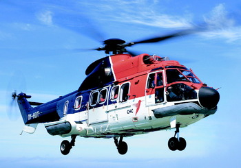
The trial platform was a Eurocopter AS.332L Super Puma operated by CHC Scotia helicopters out of Aberdeen (Figure 11) and is a typical aircraft that works in the North Sea environment for a number of operators. The trials took place on 12th September 2008 at Aberdeen airport in Northern Scotland. At this latitude as shown in Table 1, the three EGNOS geostationary satellites are at a very low elevation angle to the South.
GIANT flight trial Super Puma.

EGNOS Geo visibility from Aberdeen.

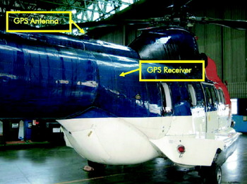
The helicopter had a typical GNSS antenna installation that is currently used as an input to a Canadian Marconi CMA3012 GPS receiver that in turn provides position input to the aircraft Flight Management System (FMS). For the purposes of the trial the aircraft's own antenna was used. The location (see Figure 12) is on the tail boom, just above the rear of the passenger cabin. This means that most received GNSS signals passed through the plane of the main rotor blades prior to reception. Additionally there was expected to be clear airframe masking from the main cabin and engine assembly ahead, as well as possibly from the tail itself to the rear. This was expected to fully obscure reception of SBAS Geo signals in a 70° arc ahead of the antenna.
Overview of trial GNSS antenna location.

The objectives of the trial were to examine:
∘ The extent to which airframe masking impacts potential SBAS satellite reception
∘ The practical implications of real world antenna installations on EGNOS performance
∘ Any potential rotor interference effects on the SBAS signals.
To this end the data collection campaign involved the installation of an SBAS capable receiver onboard the helicopter connected to the main antenna. This was configured to receive all SBAS satellites in view irrespective of any MTO that may be being broadcast. Data was also logged through the helicopter's own flight data recording system so that aircraft rotor speed and attitude parameters are available.
A series of engine run ups were performed on the ground at Aberdeen Airport with the helicopter oriented such that the SBAS signals would pass directly through the plane of the main rotor blades. This provided sufficient data to examine any clearly discernable effects of rotor interference, the analysis of which is still being undertaken.
Subsequently the aircraft undertook a series of orbits at constant bank angles and altitude. The objective of this activity was to record data on the practical masking effect on the visible SBAS geostationary satellites. It was found that engine masking caused the receiver to sequentially lose lock on the three satellites during periods where the helicopter's heading moved through due South. Whilst the period of total SBAS-signal loss was only about 20 seconds in each case, the individual satellites were each obscured for up to 100 seconds. In the operational EGNOS space segment of only two satellites this could present a risk. The horizontal and vertical protection levels calculated by the receiver were well within the requirements for APV approach procedures whilst SBAS satellites were in view, however there were notable spikes in the protection levels during periods where no SBAS satellites were being tracked. These spikes would have exceeded alarm limits for APV-II, LPV200 and APV-I approaches.
Finally a number of representative SOAP-like approaches were undertaken to the four compass headings to allow the collection of data on the practical performance of EGNOS under representative flight dynamics. The constant heading meant that there were no periods in which SBAS-tracking was completely lost, and as such the protection limits were always within APV-II alert limits. As expected flying the approach in a southerly direction caused significant constraints to the visibility of the GEOs, whilst the north-facing approach saw all three satellites being consistently tracked. Surprisingly, it was found that when flying the approach East or West only the AOR-E satellite was consistently in view. It is possible that this was due to the low antenna gain characteristics at low elevation angles resulting in successful tracking of the highest elevation satellite only.
The flight trials clearly show that in certain situations the orientation of the helicopter can cause the receiver to lose track of all SBAS satellites, denying it the guidance required to perform APV approaches. Whilst the current antenna position is well suited to providing an input for the GPS navigator, to support SOAP operations it would ideally need to be relocated to reduce the effect of engine masking.
7. CONCLUSIONS
The GIANT project has been pushing ahead with the necessary activities to make EGNOS a viable navigation system in the hazardous North Sea environment. Procedure development, safety assessment, flight simulations and flight trials all contributed to the validation of North Sea EGNOS helicopter approaches and will feed into a potential future implementation process.
ACKNOWLEDGEMENTS
The authors would like to thank Philippe Rollet of Eurocopter for his work in setting up the EGNOS flight simulations, and Jim Strachan of CHC Scotia for his work setting up the flight trials. We are also grateful to the pilots from the UK CAA, Bond Helicopters, Bristow Helicopters and CHC Scotia Helicopters for their active participation and useful feedback on the EGNOS flight simulations.