I. INTRODUCTION
Microstrip antennas are widely used in high-performance aircraft, spacecraft, satellites, and some other applications due to their advantages of low profile, conformable to planar and non-planar surfaces, simple and low cost to manufacture [Reference Ansari, Mishra, Yadav, Singh and Vishvakarma1–Reference Khedrouche and Benghalia3]. The choice of shape of an antenna opens a whole new aspect of exploration in the field [Reference Josan, Sohal and Dhaliwal4]. Extensive work on rectangular and circular geometries can be easily found in available literature. However, these geometries are not suitable for every application [Reference Sharma, Yadav, Kumar, Ranga and Bhatnagar5]. Conventional circular and rectangular microstrip antennas operate at the single-resonant frequency and radiate the linear polarization. In many practical applications, the dual-resonant frequency and circular polarizations (CPs) are required for a number of radar, communication, telecommunication, and navigation systems [Reference Kumprasert6]. Various patch configurations implemented on different types of substrates have been tested and investigated. In practice, it was found that the choice of the substrate material is of a great importance and plays a significant role in achieving the optimum radiation characteristics of the antenna [Reference Bedra, Bedra, Benkouda and Fortaki7, Reference Djouablia, Messaouden and Benghalia8].
Some substrate materials used for integrated microwave circuits or printed antennas exhibit dielectric anisotropy. This phenomenon occurs either naturally in the material or is introduced during the manufacturing process [Reference Benkouda and Fortaki9]. In addition, anisotropic substrates have become popular in the design of microwave integrated circuit components and microstrip antennas [Reference Benkouda and Fortaki9, Reference Motevasselian10]. Uniaxial substrates have drawn more attention due to their availability in materials such as sapphire, boron nitride and E-10 ceramic-impregnated Teflon. Previous studies of anisotropic materials used in microwave devices indicate that the effects of anisotropy on the performance of such structures particularly in high frequencies cannot be ignored [Reference Benkouda and Fortaki9–Reference Boufrioua12]. Furthermore, it has been shown that the performance of directional couplers can be improved using the anisotropic substrates to equalize the even and odd mode phase velocities [Reference Benkouda and Fortaki9, Reference Motevasselian10]. Therefore, many investigations have examined the effects of substrate anisotropy in microwave components performance.
The elliptical patch has been analyzed extensively using the cavity model [Reference Josan, Sohal and Dhaliwal4, Reference Motevasselian10–Reference Boufrioua12], generalized transmission line model [Reference Mythili and Das13, Reference Jung and Seo14], analysis in the Fourier–Hankel transform domain [Reference Sharma, Yadav, Kumar, Ranga and Bhatnagar5]. The method of moments (MoM) [Reference Jung and Seo14], other full-wave analyses [Reference Motevasselian10, Reference Suzuki and Chiba15], and commercial software does not provide closed-form expressions and take a long computational time. So, full-wave analysis and commercial software are not useful for direct synthesis of the patch antenna. The computer-aided design (CAD) oriented cavity model is ideal for design purposes, because it involves fewer mathematical steps than full-wave models; takes less computational times and gives results with accuracy equivalent to that of full-wave models; cost effectiveness, easy to implement, and provides close-form expressions, since the client can use a simple PC for implantation. Another advantage of the proposed model is that it takes into account the uniaxial anisotropy in the substrate.
The cavity model has been chosen as a simple alternative to analyze and predict the behavior of elliptical microstrip antennas (EMAs). Furthermore, some modifications are made to account for fringe fields, dispersion effects, and losses by calculating effective dimensions, effective relative permittivity, and effective loss tangent, respectively. However, the effect of uniaxial anisotropy in the substrate on the dual-resonant frequency of elliptical patch microstrip antenna for different structural parameter cases have been not included in the open literature.
However, we are interested in this work to study the effects of anisotropic substrate materials on the resonant frequency of an elliptical patch antenna. Moreover the study of this type of substrates is of interest, many practical substrates have a significant amount of anisotropy that can affect the performance of printed circuits and antennas, and thus accurate characterization and design must account for this effect [Reference Djouablia, Messaouden and Benghalia8]. It is shown that formulation provides accurate results within lower percentage error values with respect to the previous analyses. Thus, it can be used confidently for the determination of the effect of anisotropic substrate materials on the dual-resonant frequency of an elliptical patch antenna. The proposed model does not require any complicated mathematical functions. This is very simple, efficient, accurate and suitable for CAD applications to design wide bandwidth and high gain antenna for wireless communication.
II. ANTENNA CONFIGURATION AND DESIGN
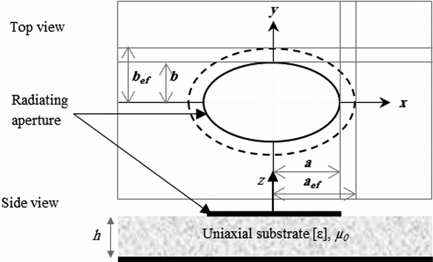
The geometrical configuration of EMA for obtaining the dual-resonant frequency (f 11eo) and circular polarizations (CPs), consists of a planar slightly elliptical patch with the semi-major axis a and the semi-minor axis b, elliptical patch is parallel to ground plane and separated from ground plane by a dielectric substrate with relative permittivity ε r and height h as shown in Fig. 1.
Geometrical configuration of EMAs for dual-resonant frequency.

The resonant frequency of elliptical waveguide [Reference Kumprasert6] can be modified and simplified for our case to yield
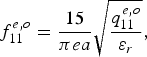 $$f_{11}^{e{\rm\comma }o}=\displaystyle{{15} \over {\pi ea}}\sqrt {\displaystyle{{q_{11}^{e\comma o} } \over {\varepsilon _r }}}\comma \;$$
where f 11eo is the dual-resonant frequency of even TM11e, and odd TM11o, mode and a is the physical semi-major axis. Generally, the measured results of the f 11eo are lower than the calculated values due to the effective (electrical) semi-major axis a ef (a ef > a).
The parameter a ef is used to account for the stored energy in the fringing field of elliptical edge. Therefore, f 11eo is a closed-form formula determined accurately by replacing the physical semi-major axis a with the effective semi-major axis a ef
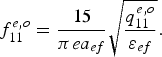 $$f_{11}^{e\comma o}=\displaystyle{{15} \over {\pi ea_{ef} }}\sqrt {\displaystyle{{q_{11}^{e\comma o} } \over {\varepsilon _{ef} }}} .$$
Determination of the exact values of Mathieu function q mneo for the given modes are rather complicated to avoid this complexity, the approximate Mathieu function q mneo of the dominant TM11eo mode, can be obtained from [Reference Sharma, Yadav, Kumar, Ranga and Bhatnagar5]
 $$\eqalign{& q_{11}^e=- 0.0049e+3.7888e^2 - 0.7278e^3+2.2314e^4\comma \; \cr & q_{11}^0=- 0.0063e+3.8316e^2 - 1.1351e^3+5.2229e^4 .}$$
The dual-frequency f 11eo with eccentricities 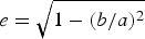 $e=\sqrt { 1 - \lpar b{\rm /}a\rpar ^ 2 } $ corresponding to the aspect ratio [Reference Kumprasert6, Reference Kumprasert and Kiranon16, Reference Long, Shen, Schaubert and Farrar17].
The effective semi-major axis should be considered the suggested approach in [Reference Suzuki and Chiba15] is applicable to the EMAs. The f 11eo of the modified structure for the TM11eo mode is calculated by modifying the equation for a circular microstrip antenna [Reference Kumprasert and Kiranon16] as given below
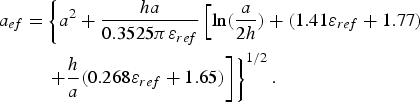 $$\eqalign{a_{ef}=& \left\{ a^2+{ha \over {0.3525\pi \varepsilon _{ref}}} \left[{\rm ln} \lpar{a \over {2h}}\rpar +\lpar 1.41\varepsilon _{ref}+1.77\rpar \right. \right. \cr & \left.\left. +{h \over a}\lpar 0.268\varepsilon _{ref}+1.65\rpar \right] \right\}^{1/2}.}$$
The effective dielectric permittivity ε ef depends on the relative dielectric permittivity ε r and the ratio of the aperture dimensions to substrate thickness of the microstrip antenna [Reference Mythili and Das13] as
 $$\varepsilon _{ef}=\varepsilon _r - \displaystyle{{0.7\varepsilon _r } \over 2}\left({\displaystyle{h \over a}+\displaystyle{h \over b}+\displaystyle{{h^2 } \over {ab}}} \right).$$
It should be pointed out that the correction to the resonant frequency (1) in formula (2) involves both the effective permittivity and the effective semi-major axis, what permits to obtain a good agreement between theory and experiment in the case of the elliptical-disk antenna.
If we want to take the substrate uniaxial anisotropy into account, the relative dielectric permittivity ε r will be replaced with the tensor ε r = diag(ε x, ε x, ε z) where ε x and ε z are the relative dielectric permittivity along x and z axis, respectively.
• For the case of isotropic substrate, the effective dielectric constant ε ef is given in equation (5).
• For the case of uniaxially anisotropic substrate, ε ef and h e given in [Reference Bedra, Benkouda and Fortaki18] is used, there resulting values are:
(6) $$\varepsilon _{eq}=\varepsilon _z\comma \;$$(7)$$h_e=h\sqrt {\displaystyle{{\varepsilon _x } \over {\varepsilon _z }}} .$$


III. NUMERICAL RESULTS AND DISCUSSION
In order to examine the computation accuracy of the approach described in the previous section, Table 1 shows the results for the resonant frequencies of elliptical-disk microstrip antenna on isotropic substrate have been compared with previously published results [Reference Kumprasert6, Reference Long, Shen, Schaubert and Farrar17].
Comparison of calculated and measured resonant frequencies of EMAs with h = 0.1575 cm, ε r = 2.48, a = 4 cm.
Absolute error % = |(f theo−f meas)|/f meas × 100.
In Table 1, the results of our model and those calculated and measured by [Reference Kumprasert6, Reference Long, Shen, Schaubert and Farrar17] are shown with corresponding percentage error values. It is observed that the results of this model are better than the results of [Reference Long, Shen, Schaubert and Farrar17, Reference Kumprasert6] for isotropic substrate case having smaller percentage error values.
Next, the effect of uniaxial anisotropy on the resonant frequency is analyzed. The anisotropy ratio (AR) is defined as
 $$AR={{\varepsilon _x } / {\varepsilon _z }}.$$
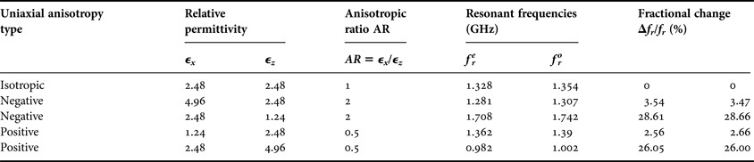
The resonant frequency of an elliptical microstrip patch antenna with dimensions a = 4 cm, b = 3.84 cm and substrate thickness h = 0.3175 cm, for different pairs of relative permittivities (ε x, ε z) is depicted in Table 2.
Dependence of dual-resonant frequency on relative permittivities with h = 0.3175 cm, ε r = 2.48, a = 4 cm, b = 3.84 cm.
The change in the dual-resonant frequency relative to the isotropic case (ε x = ε z = 2.48) is calculated using the following expression:
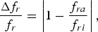 $$\displaystyle{{\Delta f_r } \over {f_r }}=\left\vert {1 - \displaystyle{{f_{ra} } \over {f_{ri} }}} \right\vert \comma \;$$
Where f ri and f ra are, respectively, the resonant frequencies of the antenna for the isotropic and uniaxial anisotropic cases. We observe that, for negative uniaxial anisotropy with AR = 2, the resonant frequency f ri, can shift to a lower value of (f re, f ro) = (1.281, 1.307)GHz or higher frequency of (1.708, 1.742). A similar remark can be made for the positive uniaxial anisotropy case with AR = 0.5; the corresponding values of lower and higher frequencies are, respectively, (0.982, 1.002) and (1.362, 1.390). Consequently, the AR parameter alone is not sufficient to enhance a decision about whether there is an increase or decrease in resonant frequency to be made.
The resonant frequencies of the elliptical patch against the substrate thickness are shown in Figs 1 and 2, where isotropic (ε x = ε z = 2.48), negative (ε x > ε z) uniaxial anisotropic and positive (ε x < ε z) uniaxial anisotropic substrates are considered.
Variation of resonant frequency with thickness of EMA, (a) even mode, (b) odd mode with; h = 0.3175 cm; a = 4 cm, where ε z varied.
In Fig. 2, the anisotropy is obtained by changing ε z while keeping ε x constant. The effect of the permittivity along the optical axis persists for low as well as for high substrate thicknesses. When ε x is changed and ε z remains constant, the influence of the resonant frequency decreases with reductions in substrate thickness as shown in Fig. 3. This influence tends to be neglected for lower substrate thickness. These behaviors agree very well with those reported for a various shapes patch antenna, by [Reference Bedra, Bedra, Benkouda and Fortaki7–Reference Djouablia, Messaouden and Benghalia8, Reference Motevasselian10–Reference Bouttout, Benabdelaziz, Benghalia, Khedrouche and Fortaki11]. We can conclude that the permittivity ε z along the optical axis is the significant and most important factor in determination of the dual-resonant frequency.
Variation of resonant frequency with thickness of EMA, (a) even mode, (b) odd mode with; h = 0.3175 cm; a = 4 cm, where ε x varied.
Figure 4 depict the influence of the aspect ratio (b/a) on the resonant frequencies (even and odd mode) of an elliptical microstrip patch antenna for three anisotropic dielectric substrate: boron nitride (ε x = 5.12, ε z = 3.4), epsilam-10 (ε x = 13, ε z =10.3), and sapphire (ε x = 9.4, ε z = 11.6). The substrate has thickness h = 0.3175 cm with varying the aspect ratios (b/a).
Dual-resonant frequencies of elliptical microstrip patch antenna versus b/a ratio for different anisotropic dielectric substrates; (a) even mode, (b) odd mode, with h = 0.3175 cm, a = 4 cm, and ε r = 2.48.
As it can be seen, the dual-resonant frequency (f re, f ro) reduces considerably when the dielectric substrate changes from boron nitride to epsilam-10, and this is in constant to happens when the medium changes from epsilam-10 to sapphire. Also it is observed that the resonant frequency decreases with increases of aspect ratios (b/a).
IV. CONCLUSION
This paper presents the expression for predicting the dual-resonant frequencies of an elliptical patch microstrip printed on isotropic or anisotropic substrate. This model is suitable for CAD and is directly applicable for the investigation of microstrip antenna in portable wireless equipment. The theoretical results are in very good agreement with experimental results. The obtained results confirm that to predict the dual-resonant frequencies variations with anisotropic substrate permittivity, it is necessary to consider both the variation of ε x and ε z, not only the ratio ε x/ε z. Other obtained results show that the dependence of the resonant frequency on ε x decreases with decreasing substrate thickness; for the thin substrates, the permittivity ε z along the optical axis is the most important factor in determining the resonant frequency. The analysis presented here can be extended to study other parameters characterizing the elliptical patch antennas with various structures.
Randa Bedra was born on September 20, 1989 in Batna, Algeria. She received her Master of Science in Microwave and Telecommunications from the University of Batna, Algeria, in 2013. She is currently with the Laboratory of advanced electronics at the Electronics Department, University of Batna, Batna, Algeria. She is currently working toward Ph.D. degree at the University of Batna. Her main research deals with numerical methods and microstrip antennas.
Sami Bedra was born on August 03, 1984 in Batna, Algeria. He obtained his Engineer and Master of Science degrees both in Electronics from the University of Batna, Algeria, in 2008 and 2011, respectively. He is currently working toward Ph.D. degree at the University of Batna. He is an Assistant Professor at the Industrial Engineering Department, Faculty of Sciences and Technologies, University of Khenchela, Algeria. He has published ten papers in refereed journals and more than ten papers in conference proceedings. His current research activities include neural network, optimization techniques, and their applications to patch antennas.
Tarek Fortaki was born on March 31, 1972 in Constantine, Algeria. He received his Engineer of Communication degree in 1995, Master Science degree in Microwaves in 1999, and Doctorate degree in Microwaves in 2004, all from the Electronics Department, Faculty of Engineering Science, University of Constantine. Currently he is a Professor at the Electronics Department, Faculty of Engineering Science, University of Batna. He has published 17 papers in refereed journals and more than 40 papers in conference proceedings. He serves as reviewer for several technical journals. His main interests are electromagnetic theory, numerical methods and modeling of antennas and passive microwave circuits.