Nomenclature
-
 $C_{f}$
-
thrust coefficient
-
$D_{i}$
-
inlet diameter of the probe (mm)
-
$D_{0}$
-
nozzle outer diameter (mm)
-
$L_{S}$
-
shock-cell length (mm)
- M
-
Mach number
-
$M_{d}$
-
design Mach number
-
$M_{e}$
-
exit Mach number
-
$P_{ref}$
-
reference pressure (20 μpa)
-
$P_{rms}$
-
root-mean-square value of input pressure signal
-
$P_{m}(t)$
-
pressure measured by mth microphone at time, t
-
$P_{n}(t+\tau )$
-
pressure measured by nth microphone at time, t +
$\tau$
-
$R_{mn}(\tau )$
-
cross-correlation function
-
$S_{t}$
-
strouhal number
- BSN
-
baseline nozzle
- DS-CHN
-
deflected seal plus chevron nozzle
- NPR
-
nozzle pressure ratio
- SPL
-
sound pressure level (dB)
- OASPL
-
overall sound pressure level (dB)
- ΔOASPL
-
Difference in overall sound pressure level (dB)
-
$\Delta f$
-
frequency resolution (Hz)
-
$\Phi$
-
azimuthal angle, measured from the downstream direction
-
$\theta _{s}$
-
shock angle
- X, Y, Z
-
Cartesian coordinates
-
$\gamma$
-
specific heat ratio


1.0 Introduction
Advanced flow control techniques are essential to mitigate high-speed jet noise. Off-design operating supersonic free-jet noise creation is usually not omnidirectional, although subsonic jet radiation is. The velocity within the core region of the supersonic jet is very high. A mixing layer encircles the core, wherein the fluid velocity diminishes radially until it approaches an insignificant value at the outside boundary [Reference Tam1]. Typically, optimally expanded supersonic jets primarily generate merely the turbulent mixing noise, with contributions from both large-scale and fine-scale turbulent eddies. In high-speed jets, large-scale turbulent eddies are likely to propagate downstream at supersonic speeds relative to the ambient sound speed. As a result, they generate strong Mach wave radiation, which readily dominates the noise emission from fine-scale turbulence. The noise emission intensity of large-scale turbulent structures depends on the jet Mach number. It is well established that effective mixing within the shear layer requires a balanced proportion of mass entraining large-scale eddies and mass transporting small-scale eddies [Reference Tam, Viswanathan, Ahuja and Panda2]. Also, it is well documented that improved mixing within the shear layer reduces turbulence and hence mixing noise emission.
Furthermore, off-design expanding supersonic jets are expected to generate complex quasi-periodic shock cells in the core region. The weak interactions between these nearly periodic shock cells and large-scale turbulent structures are expected to create additional shock-associated noise. Reduced shock strength and lesser supersonic core length achieved by flow control methods are intended to favour shock noise suppression [Reference Munday, Heeb, Gutmark, Liu and Kailasanath3]. The commonly agreed acoustic feedback mechanism is responsible for the existence of a discrete screech tone. Disrupting or breaking the acoustic feedback loop can significantly reduce or eliminate the screech noise. Imperfectly expanded supersonic jets create broadband shock noise and discrete screech noise in addition to turbulent mixing noise. The inclusion of these additional shock noises gives supersonic jet noise distinct spectral and directional characteristics [Reference Tam4]. It is obvious that improperly expanded supersonic free-jets can produce intense jet noise, resulting in noise pollution and structural failures. It is anticipated that the extreme jet noise pollution will adversely impact both technical personnel aboard aircraft carriers and residents living close to the airport [Reference Pilon, Powers, McLaughlin and Morris5]. Therefore, to develop advanced high-speed vehicles, it is essential to predict the features of jet noise and use a novel flow control approach to reduce it.
In general, flow control technologies are used to modify the jet’s structure and noise emission features. They are broadly classified as active or passive methods. In active control, a supplementary power source is used to alter the jet characteristics. In contrast, passive control obtains the regulating energy directly from the flow under control. Furthermore, limited, combined/hybrid flow control strategies have been devised to achieve additive acoustic benefits from high-speed jets. The following section shedslight on the literature from the three-flow control approaches identified (active, passive and combined/hybrid). First, some of the notable works pertinent to active flow control methods are discussed. Bauer et al. [Reference Bauer and Pannier6] introduced the oscillating mechanical flap as an active control method for Mach 0.6 free-jets. These flaps at the nozzle exit are found to excite the shear layer development favourably to decrease the jet noise radiation. Furthermore, it has been observed that noise reduction is significantly influenced by oscillation frequency. Caeti et al. [Reference Caeti and Kalkhoran7] used microjet fluid injection for Mach 1.6 free-jets. Coaxially arranged tubes inject water perpendicular to the flow direction, causing the shear layer near the microjet injection ports to bulge out as a result of barrel shock formation. The selected method entirely suppresses the screech tone. Philip et al. [Reference Morris, McLaughlin and Kuo8] studied the effect of fluidic inserts in the diverging part of the nozzle, for low bypass ratio engine applications. Operating Mach numbers 1.36 and 1.47 are selected to evaluate the existing control method. Significant noise reductions have been achieved for both mixing and shock-associated noise. Powers et al. [Reference Powers, Kuo, McLaughlin and Morris9] investigated the ability of fluid inserts in the presence of a forward flight stream. The momentum flux ratio value was found to be critical for eliminating shocks within the nozzle and jet plume. Furthermore, eliminating Mach wave radiation resulted in a significant decrease in overall sound pressure level (dB) (OASPL). Sinha et al. [Reference Sinha10] probed steady and unsteady air injection techniques to mitigate large-scale mixing noise. Experiments were conducted for a Mach number of 1.5. A spinning-value device excites the jet at frequencies close to that of the dominant turbulence structures to inject air. However, steady air injection has shown better noise reduction than the unsteady condition.
Cuppoletti et al. [Reference Cuppoletti, Gutmark, Hafsteinsson and Eriksson11] adopted a discrete fluid injection technique in the diverging portion of the nozzle with a design Mach number of 1.56. The water injection within the diverging part of the nozzle activates an extra shock structure in addition to the initial shock system. This new shock generation appears to interact destructively with the previous shocks, lowering the velocity gradient across the potential core and shock strength thus reducing shock noise radiation significantly. Samimy et al. [Reference Samimy, Webb, Esfahani and Leahy12] focused on the effect of active flow control using plasma actuators in rectangular twin jets. The investigated jet design Mach numbers are 1.3 and 1.9, respectively. The adopted perturbation-based control technique was highly successful in controlling large-scale structures. The novel idea of an active flow control system that deflects some of the adjustable seals in the diverging section of the engine exhaust nozzle was developed by Pilon et al. [Reference Pilon, Powers, McLaughlin and Morris5]. The analysis was performed for the design Mach numbers of 1.65 and 1.67, respectively. Seal deflection into the jet can allow for nearly optimal expansion to lower the shock strength by reducing an effective exhaust area. Notable noise reduction was observed along with the enhanced thrust magnitude. This comprehensive literature analysis of mechanical flaps, air, water injection, deflected seals and plasma arc demonstrates that significant jet noise reduction is possible. As defined, active control techniques can be turned on or off as needed; thrust magnitude is predicted to experience no reduction during cruise flight conditions. These methods require the use of auxiliary devices, independent water sources and tapping of air from the jet engine compressor. Practical implementation of these active flow controls is yet to be realised for full-scale applications.
The subsequent section examines the developments in the passive flow control method, which relies on the nozzle exit modifications to alter the flow structure for suppressing jet noise. Rathakrishnan et al. [Reference Vishnu and Rathakrishnan13] examined the aero-acoustic characteristics of jets from nozzles with internal grooves for the design Mach number of 1.8. The jets from the grooved nozzles feature a core jet with weak shock structure and reduced shock cell lengths. Induced vortices from the grooves are the prime reason for the reduced turbulent mixing and shock noise. Pannu et al. and Smith et al. [Reference Pannu and Johannesen14, Reference Smith and Hughes15] studied the influence of notches on off-design supersonic jets. The reduced amplitudes of the centreline pitot pressure reveal that jets from the notched nozzle feature weak shock cells as well as faster decay. Tide et al. [Reference Tide and Srinivasan16] investigated the effects of the chevron count and penetration on supersonic jet noise. The higher chevron count was discovered to be more successful for noise reduction at lower Nozzle Pressure Ratios (NPRs) and chevron penetration at higher NPRs. Munday et al. [Reference Munday, Heeb, Gutmark, Liu and Kailasanath3] evaluated the chevron impact on a 1.5 Mach jet design. All chevron nozzles showed induced axial vortices as a pair of white streaks trailing from each chevron edge. These pairs of counter-rotating vortices improve the mixing in the shear layer, resulting in smaller core jet diameters and shock-cell lengths. In addition, the chevron was found to effectively disrupt the symmetry of the jet as it cancels or diminishes the screech tone. Bridges et al. [Reference Bridges and Brown17] investigated the impact of chevron characteristics on acoustic advantages, evaluating both cold and hot flow conditions at a design Mach number of 0.9. They concluded that both the chevron count and its penetration significantly influence the jet flow structure and its acoustics.
Heeb et al. [Reference Heeb, Gutmark and Kailasanath18] investigated the penetrating impact of chevron petals on supersonic jets. The over-expanded jets demonstrated that increased penetration favoured a reduction in both components of shock noise. However, in the case of under-expansion, the contrary occurs. The authors have also stated that thrust penalty is a strong function of chevron penetration and the number of chevrons. Arun Kumar et al. [Reference Perumal and Rathakrishnan19] explored the efficiency of triangular tabs for improving mixing of a Mach 2 free-jet into its surroundings. The shortened tab’s mixing efficiency increases with a rise in the nozzle pressure ratio (NPR). Furthermore, the tabs weaken the waves inside the jet’s core, and both tabs shed mixing-promoting vortices to reduce the core jet length. Chauhan et al. [Reference Chauhan, Kumar and Rathakrishnan20] assessed the effect of aspect ratio on elliptical sonic jet decay features. The obtained results reveal that elliptical nozzles produce vortices of various sizes. These mixed-size vortices encourage large- and small-scale mixing vortices, resulting in better mixing for elliptical jets than circular jets. Aravindh Kumar et al. [Reference Kumar and Rathakrishnan21] evaluated the features of an elliptical supersonic jet at a design Mach number of 2. Once again, elliptical jets revealed superior mixing due to the creation of mixing-promoting vortices at the nozzle exit. Furthermore, the occurrence of axis switching in the elliptical jet produces greater near-field mixing than in the equivalent circular jet. Maruthupandiyan et al. [Reference Maruthupandiyan and Rathakrishnan22] studied the aerodynamic mixing of a Mach 2 jet controlled by a rectangular tab of a length equal to the nozzle exit diameter. The tabs with a shifted position provided better mixing capabilities than those at the nozzle exit. Results show that improved mixing is due to the creation of mixing-promoting vortices. Currently reviewed passive flow control methods are effective at reducing both mixing and shock noise. Despite the positive jet noise reduction outlined, these flow control approaches show significant thrust loss. Nozzles fitted with grooves, notches and tabs experience higher thrust loss than the chevron-only modification. With proper selection of chevron parameters (number of chevrons, depth of penetration and chevron length), thrust loss can be adjusted to a minimum along with notable noise suppression. The chevron technique is the only existing flow control method, successfully integrated in modern high-performance subsonic and supersonic jet applications.
This final section explores the existing combined flow control techniques for jet noise reduction. The impact of fixed corrugated seals with the chevron combination was investigated by Tinney et al. [Reference Tinney, Valdez and Murray23]. By altering the area ratio, the corrugated seals are intended to protrude into the jet flow and alter the nozzle’s design pressure ratio. Hence, the shock strength can be reduced. The discrete aggressive protrusion reduced OASPL by 1.7 dB compared to the facet form. The protrusion along with a chevron combination also produced notable noise reductions without inflicting thrust loss. McLaughlin et al. [Reference Powers and McLaughlin24] investigated the jet characteristics of a combined corrugation-bevel nozzle. The operating jet Mach numbers are 1.30 and 1.67, respectively. The proposed combined flow control technique showed a significant reduction in both shock and mixing noise. Over a broad range of polar angles and operating conditions, the newly evaluated nozzle modification decreased noise in comparison to either the only-bevelled or the only-corrugated nozzle. The acoustic properties of a Mach 0.9 jet with a mixed chevron-microjet combination were investigated by Alkislar [Reference Alkislar25]. The OASPL is reduced by 1.5–2 dB at all polar angles when the chevron-microjet combination is used. The acoustic features of a Mach 0.8 jet’s chevron-tab combination were examined by Saiyed et al. [Reference Saiyed, Mikkelsen and Bridges26]. With a thrust loss of 0.49%, the fan nozzle’s chevrons and the core nozzle’s tabs lower the effective perceived noise level (EPNL) by 3.16 dB. Similarly, the core nozzle’s 12 chevron petals and the fan nozzle’s 24 chevrons have both demonstrated a 2.7 dB decrease in EPNL and a 0.06% thrust loss. Visuanathan et al. [Reference Viswanathan, Krothapalli, Seiner, Czech, Greska and Jansen27] evaluated the aero-acoustic performance of combined and discrete control methods for the supersonic jet engine. The discrete method includes bevel, corrugation and micro jet injection. Combinations (corrugations with microjet, bevel with microjet and bevel with corrugation and microjet) were also examined. Among the various discrete flow control techniques, corrugated nozzles demonstrated considerable attenuation of shock noise. Among the examined combination approaches, corrugation in conjunction with water injection demonstrated the most significant noise reduction without altering thrust magnitude.
From this concise literature, it is obvious that only limited study on combined flow control of jet mixing without thrust penalty is available in open literature. Furthermore, combined approaches exhibit enhanced thrust and minimal thrust loss across various nozzle operating conditions. The listed combination control techniques exhibit limited research on supersonic jet noise applications. Implementing a unique combination as a control method for high-performance nozzles is crucial for mitigating dominant jet noise radiation. Upon realising the acoustic performance of combined flow control methods, the idea of adding an active deflected seal to a passive chevron creates a novel hybrid flow control combination for high-speed jet noise applications. Therefore, combining a deflected seal with the chevron is expected to provide additional acoustic benefits and may potentially reduce thrust loss, which is likely to be quantified in future work. The proposed combination is expected to yield reduced noise emission for a complex low-bypass ratio jet engine. Furthermore, existing thrust vectoring systems can be adjusted with minimal modification to incorporate deployable divergent seals featuring serrated edges. Overall, the present literature indicates that flow control approaches like active, passive and combined are predominantly examined for a single design Mach number. Hence, information on the effectiveness of listed flow control methods at different design Mach numbers is scarcely available in existing literature. Taking this as an opportunity, the suggested combination (deployable seal with chevron) is investigated for the two different design Mach numbers of 1.4 and 1.8. Besides, the recommended deployable sealmerged chevron control approach offers the flexibility for deployment as required, presumably ensuring no effect on thrust magnitude during cruise flight.
2.0 Experimental details
2.1 Jet flow facility
For the investigation, experiments were conducted in the supersonic free-jet facility at the Gas Dynamics and Propulsion Laboratory at SASTRA Deemed to be University in Tamilnadu, India. Compressed air from storage tanks is ducted through a pressure-regulating valve to a settling chamber, where it is brought to the equilibrium stagnation condition. To avoid condensation and contamination, compressed air is delivered through a dehumidifier and filters. The existing blowdown facility is equipped with an integrated air dryer for managing the dew point. The compressed air is dried to a dew point of approximately 6−7°C, which is sufficiently low to prevent moisture condensation and shock-like disturbances within the nozzle. In addition, during the entire experiment duration, average daily temperatures ranged from highs of approximately 36−38°C to lows of 27−28°C, with humidity levels averaging between 63% and 73%. The pressure control valve in the supply line provides for a steady pressure in the settling chamber. Since the backpressure (Pb) was the atmospheric pressure (Pa) into which the free-jet was discharging, we controlled the settling chamber pressure (P0s) to achieve the preferred NPR. The NPR is the ratio between the stagnation pressure measured in the settling chamber (P0s) and the ambient pressure (Pa). Figure 1 shows the supersonic free-jet facility integrated with the probe setup for nozzle calibration.
Schematic representation of supersonic free-jet facility along with the probe setup.

2.2 Investigated nozzle models
The fabricated baseline nozzles (BSN) are designed for Mach numbers of 1.4 and 1.8, with corresponding area ratios of 1.115 and 1.439, respectively. These nozzles are constructed from grade 304 stainless steel. At a 1° angle into the jet, six deflected seals are employed, with an alternate deflection. With a steady decrease to zero at the throat and an included angle of 1° at the nozzle exit, the deflected seals are replicated as solid wedges to increase structural integrity [Reference Pilon, Powers, McLaughlin and Morris5]. Similarly, chevron implementation includes a nozzle with six petals, zero penetration and a length of 0.5 De for each petal [Reference Munday, Heeb, Gutmark, Liu and Kailasanath3, Reference Tide and Srinivasan16]. If seals are deflected, the deflection angle is expected to cause a penetration effect. Subsequently, chevrons were integrated with the diverging seals to create the hybrid flow control technique (Figure 2). Following the construction of the nozzle, it is crucial to verify if the design Mach number is being attained. The nozzle exit plane is segmented into nine distinct points to measure the jet’s total and static pressures, as shown in Figure 5. Measurements are done at the vertices of this grid to quantify the nozzle exit Mach number. For the nozzle to display all three expansion modes, for a design Mach number of 1.8, the NPRs considered range is from 2.75 to 6.75. Likewise, for the design Mach = 1.4, the NPR ranged from 2.25 to 6.25. For all tested NPR levels, an absolute pressure scale is used. A pitot and long-cone probe are used to measure downstream total pressure (P02), and the jet’s static pressure (P1). The intake of the pitot tube was chambered to mitigate flow spillage and make the probe less sensitive to the yawing angle [Reference Nikam and Sharma28]. Both probes are attached to an industrial pressure transducer from TE Sensor Solutions, the M5200 series; it collects information at a sampling rate of 1000 Hz and records data for five seconds. Rayleigh’s pitot formula (Equation (4)) is used to estimate the nozzle exit Mach number. Both BSNs are calibrated only for the design Mach numbers of 1.4 and 1.8. A nearly uniform distribution is observed across the nozzle exit at these design NPRs.
3D representation of (a) BSN (b) Chevron nozzle (c) deflected seal nozzle and (d) deflected seals with chevron mounted nozzles.

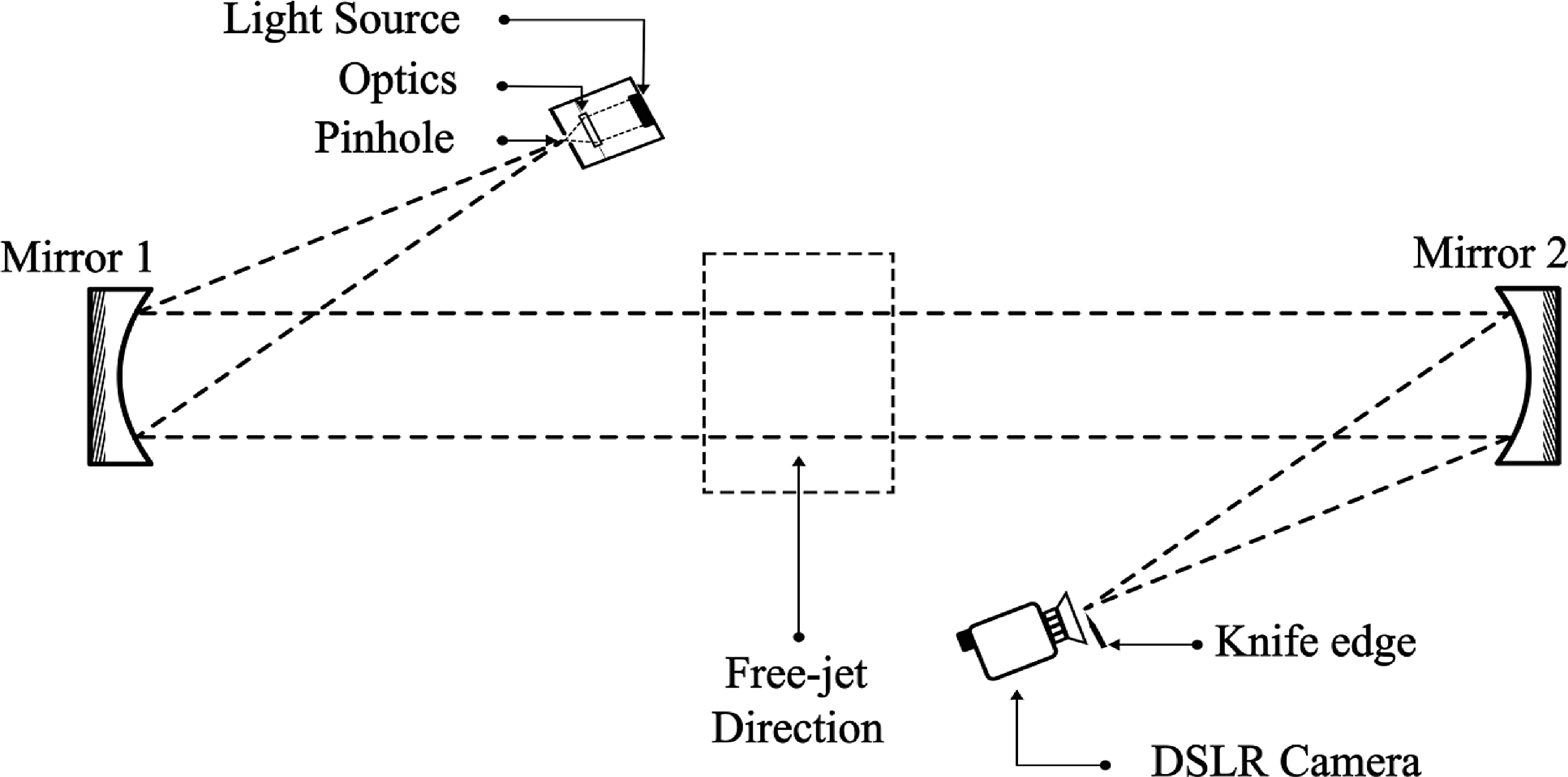
Schematic of classical Z-type Schlieren setup for supersonic Jet visualisation.

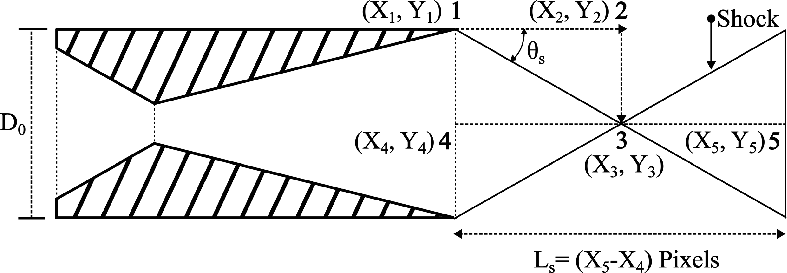
Schematic of mathematical model to calculate the shock angle and shock cell length.

2.3 Experimental setup for jet flow visualisation
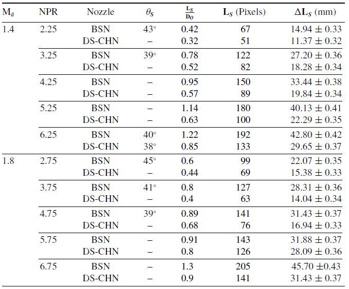
Supersonic jet structures are visualised using the classic Z-type Schlieren visualisation technique (Figure 3). To ascertain the impact of modifications on the jet structure, the jet structures of the baseline and nozzle with the adopted hybrid flow control method are acquired and compared. The current Schlieren system includes a screen stand, two 125 mm concave mirrors, a knife edge and a 50-watt continuous white light source. The images are taken with a Canon EOS 80D DSLR camera. The camera captures 100 background and 100 jet flow photos for every NPR. Image processing is done to improve the image quality and gather the required information. To reduce high-frequency noise, the background and jet images are time-averaged and filtered using a Butterworth low-pass filter. Background subtraction helps to bring out concealed flow features. This also removes the varying illumination across the image to some extent. Kontis and Rajesh et al. [Reference Li, Burak Agir, Kontis, Ukai and Rengarajan29, Reference Paramanantham, Janakiram and Gopalapillai34] had analysed the Schlieren images by quantifying the supersonic jet structure parameters like core jet length and Mach stem height for the off-design supersonic jets. Our present research also adopted the same method to determine features such as shock cell lengths and shock angles in the jet structure. The mathematical model adopted to calculate the shock angle (θS ) and shock cell length (Ls ) is shown in Figure 4. The calibration of the image is carried out in the following manner. The nozzle outer diameter is a known physical dimension (i.e. Do = 35 mm), which is approximately 157 pixels in length in the Schlieren image. These 157 pixels correspond to 35 mm, which translates to 1 pixel to 0.223 mm in dimension. The calibrated value of the pixels converts the shock-cell length measured in pixels to physical length in millimetres. The error in the measurement of the shock-cell length and nozzle outer diameter is given in terms of the pixels or millimetres. The methodology for determining the uncertainty values mirrors that of Reference [Reference Paramanantham, Janakiram and Gopalapillai34]; dimensionless shock-cell length values are transformed into pixels, and the final results are presented in millimetres. The calculated uncertainty values for both the design Mach numbers (1.4 and 1.8) and the range of NPRs are presented in Table 1. The uncertainty values range from ± 0.32 mm to ± 0.42 mm; this minimal variance maintains the relative tracking error below 3% for all measured values, thereby confirming a highly reliable experimental resolution.
Comparison of shock angle and shock-cell length with its uncertainty values

Table 1. Long description
A table comparing shock angle and shock-cell length with uncertainty values for different nozzle pressure ratios (NPR) and Mach numbers (M d). The table has 12 rows and 7 columns. Column headers are M d, NPR, Nozzle, θ s, L s / D o, L s (Pixels), and ΔL s (mm). Row labels are not present. The table presents data for two Mach numbers, 1.4 and 1.8, with varying NPR values. For each combination of M d and NPR, the table lists the nozzle type, shock angle (θ s), dimensionless shock-cell length (L s / D o), shock-cell length in pixels (L s (Pixels)), and the uncertainty in shock-cell length (ΔL s (mm)). The data shows variations in shock angle and shock-cell length for different NPR values and nozzle types, with corresponding uncertainty values.
2.4 Acoustic measurements and data processing
Far-field acoustics is used to examine the noise generated by free-jet that exits from baseline and modified nozzles at two identified design Mach numbers (1.4 and 1.8). A minimum arc radius of 35 times the nozzle exit diameter is necessary to provide a geometrical and true far-field effect. Additionally, to enhance the far-field influence on the jet’s acoustic data, a marginally higher arc radius is also used to enable true and geometric far-field measurements [Reference Viswanathan30, Reference Viswanathan31]. Hence, for the present analysis, far-field measurements are made with a polar arc radius of 60 times the nozzle exit diameter. All acoustics measurements are collected at five different azimuths (30°, 60°, 90°, 120° and 135°) as illustrated in Figure 5. However, measurements from three locations are presented in this paper to explore specific jet acoustic signatures at 30° (dominance of large-scale turbulent mixing noise), 90° (dominance of shock-associated noise) and 135° (dominance of screech noise) azimuths.
Acoustic source identification using microphones at peak acoustic source radiation angles of 30°, 90° and 135° was possible. However, this approach is likely to experience minimal deviation from exact source identification due to inherent overlap. Because of this, precise isolation of the broadband shock-associateId noise (BBSAN) and its subsequent shift within the sound spectra is certainly limited [Reference Ahuja32]. All three angular measurements are taken at locations in an anti-clockwise direction from the jet axis. Measurements are carried out at the XZ plane. A typical illustration of the arrangement of pressure transducers and nozzle exit plane grid arrangements is given in Figure 5.
Schematic of setup for acoustic measurements and the nozzle exit plane grid arrangement.

Acoustic measurements are performed using Integrated Circuit Piezoelectric (ICP) pressure sensors (PCB make, model 112A22) with a sensitivity of 100mV/psi. The sensors are held rigidly on stands directed towards the jet such that the sensor surface faces the jet axis perpendicularly. The stands and the sensor mounts are covered with acoustic foam to prevent wave reflection. Furthermore, the distance between the centre of the nozzle exit and the pressure transducer remains constant [Reference Ahuja32, Reference Viswanathan33]. Acoustic data is collected for 0.5 s at a sampling rate of 100 kHz per channel using simultaneous sampling in five channels via an NI PCIe 6413 DAQ card. The entire experiment is carried out in an open atmosphere to eliminate reflection of waves from nearby surfaces. LABVIEW software is used to acquire the data on a computer. Unsteady pressure measured by the transducers is converted to an amplitude-frequency domain using Fast Fourier transform on a MATLAB platform. To estimate the noise generated by the jet, the unsteady pressure obtained is converted to sound pressure level (SPL) and OASPL values using Equations (1) and (2). The sound pressure level is calculated against a 20 μPa reference pressure. The SPL spectrum is plotted against the non-dimensional Strouhal number. The Strouhal number is defined as
 $S_{t}=fD_{j}/U_{j}$
, where
 $U_{j}$
is the jet velocity,
 $D_{j}$
is the fully expanded diameter of the jet and
 $f$
is the frequency [Reference Tam, Parrish and Viswanathan37]. Similarly, the difference in overall sound pressure level (ΔOASPL) is also calculated (Equation 3) to quantify the ability of the combined nozzle to suppress the jet noise radiation. The OASPL is calculated by integrating the sound pressure spectra from St (min) = 0.01 to St (max) = 2.50, for all three observed angles. The screech tones are retained while calculating the OASPL to reflect the actual total energy emission. Multiple measurements were done at the same location, and the peak of SPL values was observed to be within ± 0.5 dB of the mean value obtained for six sets of data at the same NPR. The experimental uncertainty was estimated at ±2% of the measured data for the same data set.
 \begin{align} SPL(dB)=10\log _{10}\left({P^{\prime}_{rms} \over P_{ref}}\right)^{2} \end{align}
 \begin{align} \textit{OASPL}(dB)=10\log _{10}\left[(\Delta f)\mathop{\sum }\limits_{i=1}^{i=n}10^{{SPL(\,f) \over 10}}\right] \end{align}
 \begin{align} \Delta \textit{OASPL}(dB)=(\textit{OASPL})_{BSN}-(\textit{OASPL})_{DS-CHN} \end{align}
 \begin{align} {P_{02} \over P_{1}}=\left({\left(\gamma +1\right){M}_{1}^{2} \over 4\gamma {M_{1}}^{2}-2\left(\gamma -1\right)}\right)^{{\gamma \over \gamma -1}}\left({1-\gamma +2\gamma {M}_{1}^{2} \over \gamma +1}\right) \end{align}
3.0 Results and discussion
This section is divided into four subsections. The first section analyses jet structures using the Schlieren visualisation, while the second examines the acoustic signatures of the modified nozzles in comparison to the base nozzles. Third, statistical analysis was performed with the acquired data to separate out the multiple noise sources and their acoustic features. Finally, crackle jet noise occurrence is also discussed. During this entire testing, the jet was operated in the `cold jet’ mode, with the reservoir temperature set to the ambient temperature.
3.1 Jet flow visualisation
The jet structures for the BSN and combined/hybrid flow control nozzles (deflected seal plus chevron nozzle as DS-CHN) for both design Mach numbers (Md = 1.4 and 1.8) have been visualised and compared across a range of NPRs. Comparing the jet structures of the combined flow control nozzle with the baseline is likely to reveal the modifications in jet structures. Hence, the effectiveness of combined flow control techniques on jet modification and noise control can be well understood. In general, supersonic jet noise control is twofold: the control should yield a reduced core jet length, and shock cells in the core jet should be made weaker [Reference Munday, Heeb, Gutmark, Liu and Kailasanath3, Reference Tide and Srinivasan16]. Disrupting the acoustic feedback loop by breaking the jet symmetry can decrease or eliminate the screech noise [Reference Heeb, Gutmark and Kailasanath18, Reference Nikam and Sharma28]. Lastly, improved mixing within the shear layer is likely to augment the shear layer thickness. This, in turn, reduces the intensity of velocity gradient across the jet plume, resulting in reduced mixing noise radiation [Reference Tam4, Reference Heeb, Gutmark and Kailasanath18]. The flow visualisation study begins with Mach 1.4 jet formations. Instantaneous shock-cell images are averaged to highlight the more stationary shock cells by decreasing unsteadiness within the jet plume. Figure 6 illustrates the Schlieren images of the base nozzle for all studied NPRs (2.25–6.25); it can be perceived that the initial shock cells are more defined than the subsequent cells. The cumulative effect of many shock reflections from the oscillating sonic line within the shear layer results in consecutive shock cells seeming more diffused than earlier ones [Reference Munday, Heeb, Gutmark, Liu and Kailasanath3]. Differences in static pressures inside and outside the jet generate quasi-periodic shock cells. These shock cells oscillate back and forth as they interact with growing turbulence downstream [Reference Tide and Srinivasan16]. An increase in NPR allows the jets exiting from the BSN to expand their supersonic core dimensions. Consequently, it may be observed that at higher NPRs, axial and radial extensions of the core jet occur. At elevated NPRs (5.25 and 6.25), BSNs exhibit moderate and highly under-expanded symmetric jets. The mild and significant Mach stem formation, enabled by the barrel shocks, is evident at both NPRs (Figure 6d and e). Development of these high-strength shock cells within the core jet aids augmented jet noise radiation into the atmosphere [Reference Tam4]. Apparently, for all studied NPRs, jets emerging from BSNs have symmetric jet structures, characterised by uniform shear layers.
Schlieren images of baseline and combined/hybrid flow control nozzle (Md = 1.4).

Schlieren images of baseline and combined/hybrid flow control nozzle (Md = 1.8).

The jet structures of the combined flow control nozzle are compared to those of the baseline for all identified NPRs. The controlled jet core exhibits reduced shock strength and increased instability, leading to a less-defined first shock cell. Firstly, the deflection of seals into the jet axis is expected to modify the design pressure ratio of the nozzle by decreasing the effective exhaust area, hence weakening the shock cells within the jet [Reference Pilon, Powers, McLaughlin and Morris5]. Secondly, each deflected seal-fused chevron petal can induce a pair of counter-rotating stream-wise vortices, which significantly enhance mixing between the high-velocity jet and the surrounding air [Reference Munday, Heeb, Gutmark, Liu and Kailasanath3, Reference Tinney, Valdez and Murray23]. These two advantageous flow modifications result in weaker shocks within the jet core and increased turbulence, further diffusing the shock cells. The combined nozzle’s jet has more dissipated shock cells at NPR 3.25 (Figure 6g) than the BSN. Moreover, the length of the shock cell reduces as the thickness of the shear layer grows. The axial position of wave reflections from the shear layer is more readily observable than the locations where the shock cells converge at the jet centreline.
The distance between these reflections will be used to determine the shock cell length [Reference Munday, Heeb, Gutmark, Liu and Kailasanath3]. The dimensionless length (
 $L_{S}/D_{0})$
of the second shock cell for both jets is quantified according to the mathematical model illustrated in Figure 4, where the second shock cell length is
 $L_{S}$
and the nozzle’s outer diameter is
 $D_{0}$
. The second shock cell is chosen, as it can be precisely defined for the jets emerging from the baseline and modified nozzles. Figure 6 presents the quantified values of
 $L_{S}/D_{0}$
for both jets, clearly illustrating the extent of shock-cell length reduction. The magnitude of shear layer thickness growth and the decrease of supersonic core jet dimensions elevate with an increase in NPR. Lastly, a jet emerging from the combined nozzle at an NPR of 6.25 exhibits no Mach stem; however, it is characterised by strong shocks with a higher shock angle of 38°. Consequently, the proposed hybrid/combined flow control nozzle facilitates two significant alterations: reduced dimensions of the supersonic core jet and augmented shear layer thickness.
Figure 7 depicts the jet flow developments of Mach 1.8 for the baseline as well as modified nozzles. The jets exiting from the BSN demonstrated more pronounced first shock cells than the others for all studied NPRs (Figure 7a–e). As the shear layer expands toward the jet centreline and its surroundings, mixing gradually weakens the subsequent shock cell formations, leading to their eventual dissipation downstream [Reference Chauhan, Kumar and Rathakrishnan20]. As a result, the increasing dissipation causes each successive shock cell to appear more smeared than the one before. At NPR = 2.75 (Figure 7a), the BSN experiences a highly over expanded jet (i.e. Pe « Pa ). In order to compress the flow leaving the nozzle with the static pressure (Pe ) and bring it into balance with the back pressure (Pa ), an oblique shock with a higher shock angle (θS = 45°) with a Mach stem formation is required. In contrast, for the hybrid/combined flow control nozzle running at the same NPR, the initial shock cell appears without the Mach stem (Figure 7f). Thus, the absence of the Mach stem indicates a reduction in shock strength and enhanced mixing of the over-expanded controlled jets. At NPRs 3.75 and 4.75, BSN displays moderate and mild over expanded jets (Figure 7b, c). A gradual surge in operating pressure close to the design pressure reduces the intensity of overexpansion. Thus, a reduction in shock strength can be observed with a decrease in shock angle (θs = 41° at NPR 3.75 and θs = 39° at NPR 4.75). The first shock cell of the jet emerging from the dual flow control nozzle at NPR 3.75 looks to be further diffused than the baseline. Likewise, all the shock cells within the core jet appear to be highly dissipated for NPR 4.75.
At higher NPRs 5.75 and 6.75, the jets exiting the BSN exhibit moderate and highly under-expanded flow regimes. The potential core of the under-expanded jet extends over a greater length dictated by multiple shock cells visibly producing a thinner shear layer. Hence, axially and radially extended shock cells are apparent within the jet’s core (Figure 7d, e). However, the combined/hybrid flow control nozzle generates significantly diffused shock cells, resulting in a reduced supersonic core diameter and length (Figure 7i, j). Rask et al. [Reference Rask, Gutmark and Martens35] found that the discrete chevron nozzle’s shock cell pattern dissipates faster than a BSN’s because of enhanced turbulence by axial vortices in the jet mixing layer. Pilon et al. [Reference Pilon, Powers, McLaughlin and Morris5] similarly reported that individual deflected seals generate vortices upon deflection to promote mixing between adjacent streams. The suggested hybrid flow control nozzle is expected to generate vortices of different sizes due to the non-circular exit and the size of the vortex generated is proportional to the radius of curvature of the edge from which it is shed. Hence, right proportion of induced small-scale and large-scale vortices are anticipated to optimise the mixing, that greatly aggregates the mixing layer growth into the potential core. This enhanced mixing enables higher energy transfer between the core jet and entrained atmospheric air, thus reducing shock strength and core jet dimensions [Reference Munday, Heeb, Gutmark, Liu and Kailasanath3]. In addition, improved mixing within the shear layer is likely to augment its thickness. However, the dimensions of supersonic core jets (i.e. the lengths and widths of shock cells) are likely to decrease proportionally (Figure 7i, j). This reduction, in turn, diminishes the intensity of the velocity gradient across the jet plume, leading to a decrease in mixing noise radiation [Reference Tam4, Reference Heeb, Gutmark and Kailasanath18]. Seiner et al. [Reference Seiner39] derived the empirical relation to quantify the average shock cell length as given in the Equation (5).
 \begin{align} {\overline{L} \over D}=a\beta ^{b}=a\left({M_{j}}^{2}-1\right)^{\frac{b}{2}} \end{align}
 \begin{align} T_{SC}={L_{1} \over U_{c}}+{L_{1} \over a_{0}}={L_{1} \over U_{c}}.\left[1+M_{c}\right] \end{align}
3.2 Free-jet acoustic emission
In general, an imperfectly expanded supersonic jet exiting a convergent-divergent nozzle produces extra shock noise (screeches and a broadband shock component), in addition to the jet mixing noise [Reference Tam4]. The acoustic source distributions for supersonic jets can be grouped into three distinct regions based on the Strouhal number. The lowest Strouhal number region is dominated by jet-mixing noise (i.e. the left side of the screech tone as in Figure 8). At the highest Strouhal numbers, jet noise radiation consists of BBSAN and discrete screech noise. The discrete spike observed at a specific frequency within the lower range of the spectrum corresponds to the screech tone. The final region is characterised by Strouhal numbers that fall between the two previously mentioned, and they approximately correspond to both jet-mixing noise and shock noise, which are at comparable levels [Reference Seiner39–Reference Tam and Tanna41]. To limit the number of markings, only the lowest NPR of sound spectra for the design Mach number 1.4 is indicated for the respective acoustic sources in Figure 8. The following section clarifies the acoustic characteristics of the BSN and the DS-CHN nozzles designed for a Mach number of 1.4. Subsequently, the acoustic properties of the M = 1.8 jet were also investigated. For conciseness, we present the results obtained at three specific azimuths: 30° (downstream direction), 90° (sideline direction) and 135° (upstream direction).
The SPL distribution of BSN and DS-CHN nozzles at NPR = 2.25.

Figure 8 describes the SPL for NPR = 2.25 at three different locations (30°, 90° and 135°). The fundamental screech tone and its accompanying harmonics are apparent at all three azimuths. Screech results from an acoustic feedback phenomenon arising from a shock-turbulence interaction. This occurs when the thinnest part of the shear layer becomes acoustically excited, leading to the production of a large-scale instability wave that propagates along the mixing layer. The instability wave grows as it propagates downstream and eventually has enough energy to interact with a shock cell and produce a high level of noise [Reference Tam4, Reference Williams, Simson and Virchis42]. Powell’s screech resonant loop involves a time cycle (TSC) equal to the sum of the eddy convection time from the nozzle to shock and the return time of sound propagating external to the jet from shock to nozzle (Equation 6), where, L 1 is the length of the first shock cell, Mc is the eddy acoustic Mach number, a 0 being the ambient speed of sound and Uc is the eddy convective velocity. A powerful screech generates multiple harmonics, and the radiation patterns differ distinctly from those of the fundamental peak. Moreover, the screech tone’s primary radiation direction points upstream, towards the nozzle exit [Reference Tam, Ahuja and Jones36, Reference Tam, Parrish and Viswanathan37]. The screech tone occurs at St = 0.23, with intense and higher-order harmonics dominating the spectra at 30° and 135°. In contrast, minimal and less-intense harmonics distinguish the 90° azimuth. The DS-CHN demonstrates a screech noise reduction of 2.8 dB at 90° and 1 dB at 135°. For identical azimuths, the jets from the BSN produce screech tone levels of 157.8 and 156 dB, respectively. Conversely, at 90°, the DS-CHN demonstrates screech noise increment of ∼ 1 dB than the BSN. Equations 2 and 3 calculate the overall sound pressure level and the difference. The difference in ΔOASPL for the DS-CHN shows the noise reductions of 0.5 dB across all three azimuths (30°, 90° and 135°).
Figure 9 illustrates the SPL at an NPR of 3.25. Again, sound spectra at 30° and 135° have more harmonics. But, for the 90° azimuth, the opposite is true. The measured screech noise levels for the BSN are 159.5 dB at 30°, 157 dB at 90° and 158.2 dB at 135°, respectively. Correspondingly, for the same NPR and azimuths, the DS-CHN exhibits screech tone levels of 157, 156 and 156.2 dB, respectively. Thus, the significant decreases in screech noise levels (2.5 dB at 30°, 1 dB at 90° and 0.8 dB at 135°) indicate the effectiveness of DS-CHN to interrupt the acoustic feedback loop that generates it. Notably, at an angle of 90°, the SPL decay following the fundamental screech tone is less pronounced than the sound spectrum observed at the other two azimuths. The ΔOASPL shows that the DS-CHN at NPR 3.25 attenuates noise by 0.5 dB compared to the BSN at azimuths of 30° and 135°. However, at 90°, the DS-CHN experiences a significant reduction of 2.5 dB compared to the BSN. This drop results from the diminished shock strength attributed to the alteration in the DS-CHN area ratio due to the seal deflection into the jet.
The SPL distribution of BSN and DS-CHN nozzles at NPR = 3.25.

The SPL distribution of BSN and DS-CHN nozzles at NPR = 4.25.

Figure 10 shows the SPL of BSN and DS-CHN at NPR 4.25. The influence of harmonics on the sound spectra is noticeably reduced at all three observed locations compared to the previous two NPRs (2.25 and 3.25). Notably, at 90° azimuth, the sound spectrum shows merely a single harmonic. In addition, screech magnitudes at 135° show that the DS-CHN exhibits a reduction of 3 dB. In contrast, at 30° and 90°, DS-CHN experiences a 1 dB increment. A diminished acoustic feedback loop results in the generation of fewer and less intense harmonics. The existing development is anticipated to emit limited and weak secondary harmonics of fundamental screech [Reference Tam, Parrish and Viswanathan37], predominantly radiating in the lateral directions of the jet. Hence, the marginally weak feedback loop restricts the production of secondary harmonics, leading to a negligible quantity of harmonics at 90° azimuth. The jet emanating from the DS-CHN demonstrated a more significant SPL decline than the BSN in the lower Strouhal number ranges. This reduction is apparent across all measured azimuths (30°, 90° and 135°), rendering the fall in OASPL significantly evident. At an azimuth of 30°, the DS-CHN’s OASPL is 2 dB lower than the BSN. Besides, the sideline (90°) and upstream (135°) directions of the DS-CHN exhibit merely a 0.5 dB reduction in noise.
The SPL distribution of BSN and DS-CHN nozzles at NPR = 5.25.

The SPL distribution of BSN and DS-CHN nozzles at NPR = 6.25.

The SPL distribution of BSN and DS-CHN nozzles at NPR = 2.75.

Figures 11 and 12 depict the SPL of jets emanating from BSN and DS-CHN at higher NPRs (5.25 and 6.25). The sound spectrum for both NPRs, observed at 90° azimuth, displays no harmonics. Hence, the spectra on the right side of the screech consist of merely BBSAN. The localised interaction between the shock waves and the turbulent shear layer generates broadband shock-associated noise. Consequently, the endpoints of each shock cell function as sources of shock. The term ‘shock source’ refers to the origins of noise generated by the repeated interactions of convecting turbulence at the termination of each shock cell. Sources that span a wide range of Strouhal numbers reflect this repetitive interaction between shock waves and turbulence [Reference Seiner39, Reference Breen and Ahuja40]. In addition, shock noise intensity is proportional to the supersonic core jet length and strength of the shock cells. Consequently, the magnitude of shock-related noise will also vary as given by the following theoretical scaling-formula as given in Equation 7. At a 30° azimuth, the impact of harmonics is comparatively less significant than the previously described NPRs (2.25–4.25). However, 135° still encounters notable numbers of harmonics within the sound pressure spectrum. The higher the NPR (5.25 & 6.25), the greater the radial expansions of the jet at the nozzle exit, owing to the favourable pressure gradient. Deflected seal-fused chevron petals penetrate the outward-expanding jet deeply, while non-deflected ones penetrate moderately. At the exit plane, the DS-CHN has azimuthal asymmetry due to alternate deflection. Hence, the DS-CHN generates vortices of different intensities and sizes to optimise mixing within the shear layer. This enhanced mixing aims to thicken the shear layer, while disrupting jet symmetry. As a result, convoluted jet symmetry critically limits the emission of both the primary and secondary harmonics. The DS-CHN screech noise at NPR 5.25 is measured to be 2.5 dB lower at 135° azimuth compared to the BSN; however, at other locations, it is 1 dB higher. The DS-CHN at NPR 6.25 shows approximately a 1 dB reduction in screech noise amplitude at 90° and 135° azimuths. However, the magnitude of the 30° fundamental screech tone remains unchanged between BSN and DS-CHN. The predicted OASPL indicates that, at a 30° angle, the DS-CHN reduces the noise level by 3.5 and 4 dB for NPRs of 5.25 and 6.25, respectively. Hence, it is evident that as the NPR increases, the efficiency of the DS-CHN in mitigating primary low-frequency mixing noise significantly improves. Similarly, in the upstream direction (135°), the DS-CHN demonstrated a reduction of 0.5 to 1 dB compared to the BSN. Conversely, in the lateral direction (90°), the DS-CHN displayed an increase in noise intensity of approximately 0.5 to 1 dB, exceeding that of the BSN.
 \begin{align}I_{\left(\textit{shock}\;\textit{associated}\;\textit{noise}\right)\;\propto\;{\left({M_{j}}^{2}-{M_{d}}^{2}\right)^{2}}} \end{align}
The following section outlines the jet noise characteristics of a Mach 1.8 nozzle. To produce overexpanded, optimally expanded and underexpanded supersonic jets, the NPRs are adjusted between 2.75 and 6.75. The SPL characteristics of baseline and deflected seal-chevron nozzles at NPR 2.75 are plotted against the Strouhal number in Figure 13. It is well observed that harmonics of the fundamental screech tone dominates the 135° azimuth (i.e. upstream direction). However, 30° and 90° locations meet the marginally less intense harmonics at the higher Strouhal number ranges. The harmonics are, of course, produced only when the screech is particularly strong. Furthermore, the weakest link theory suggests that the interaction between excited instability waves and the shock cells of the jet flow is responsible for generating a screech tone [Reference Tam, Parrish and Viswanathan37]. Measured screech tone magnitudes for the DS-CHN also exhibit only minimal reduction ∼ 1 dB in the sideline direction (90°). Figure 14 describes the SPL associated with the NPR of 3.75. Still, 90° and 135° azimuths are influenced by the marginally less-intense harmonics of the fundamental screech tone. However, azimuth 30° meets the minimal number of harmonics. Besides, only 1 dB screech noise reduction for the DS-CHN is realised from both the sidel line (90°) and upstream directions (135°). As previously discussed, two NPRs (2.75 and 3.75) are operating well below the design NPR (5.75). The strong shocks appear at the nozzle exit to balance out the excessive pressure difference. These high-strength shock cells can interact strongly with the induced instability waves for a robust feedback loop responsible for inducing strong screech tone and subsequent harmonics as identified in Figures 13 and 14. At an NPR of 3.75, the fundamental screech tone and harmonic structures exhibit reduced intensity compared to those at 2.75. The OASPL and its variation ΔOASPL for the DS-CHN demonstrate an approximate reduction of 0.5 dB compared to the BSN. The observed reduction is identical across all three azimuths for the NPR of 2.75. Likewise, at NPR 3.75, upstream (135°) and downstream (30°) orientations from the DS-CHN show a 2.5 and 0.5 dB noise reduction, respectively. Conversely, at the 90° azimuth, there is an increase of 0.5 dB relative to the BSN. The overexpanded jet configurations and their prominent adverse pressure gradient (i.e. converged jet structure) significantly limit the effectiveness of flow control techniques.
The SPL distribution of BSN and DS-CHN nozzles at NPR = 3.75.

Figure 14 Long description
The image contains six line graphs comparing the sound pressure levels (SPL) of BSN and DS-CHN nozzles at a nozzle pressure ratio (NPR) of 3.75. The graphs are organized into two columns, each representing a different nozzle design: BSN on the left and DS-CHN on the right. Each column contains three line graphs corresponding to different angles: 135 degrees at the top, 90 degrees in the middle, and 30 degrees at the bottom. The x-axis of each graph represents the Strouhal Number, ranging from 0 to 2.5. The y-axis represents the sound pressure level (SPL) in decibels (dB), ranging from 100 to 160. Each line graph shows the SPL distribution for the respective nozzle design and angle. The graphs illustrate how the SPL varies with the Strouhal Number for each nozzle design and angle, highlighting differences in noise characteristics.
Figures 15 and 16 illustrate the SPL spectra of jets emanating from BSN and DS-CHN at higher NPRs (5.75 and 6.75). The sound spectrum of the jets exiting both nozzles at a 30° azimuth is nearly free from the harmonics of the fundamental screech tone. However, the sideline (90°) and upstream directions (135°) exhibit modest and strong harmonics, respectively. The spectral properties of NPR 6.75 at all three azimuths are almost indistinguishable from those of NPR 5.75.
The SPL distribution of BSN and DS-CHN nozzles at NPR = 5.75.

The SPL distribution of BSN and DS-CHN nozzles at NPR = 6.75.

Figure 16. Long description
Two sets of line graphs compare sound pressure levels (SPL) for different nozzle designs at varying angles. The left set is labeled BSN and the right set is labeled DS-CHN. Each set contains three line graphs corresponding to angles 135 degrees, 90 degrees, and 30 degrees. The x-axis represents the Strouhal Number ranging from 0 to 2.5, and the y-axis represents SPL in decibels (dB) ranging from 100 to 160. Each line graph shows fluctuations in SPL across the Strouhal Number range. The graphs indicate variations in noise levels and shock structures for the different nozzle designs and angles.
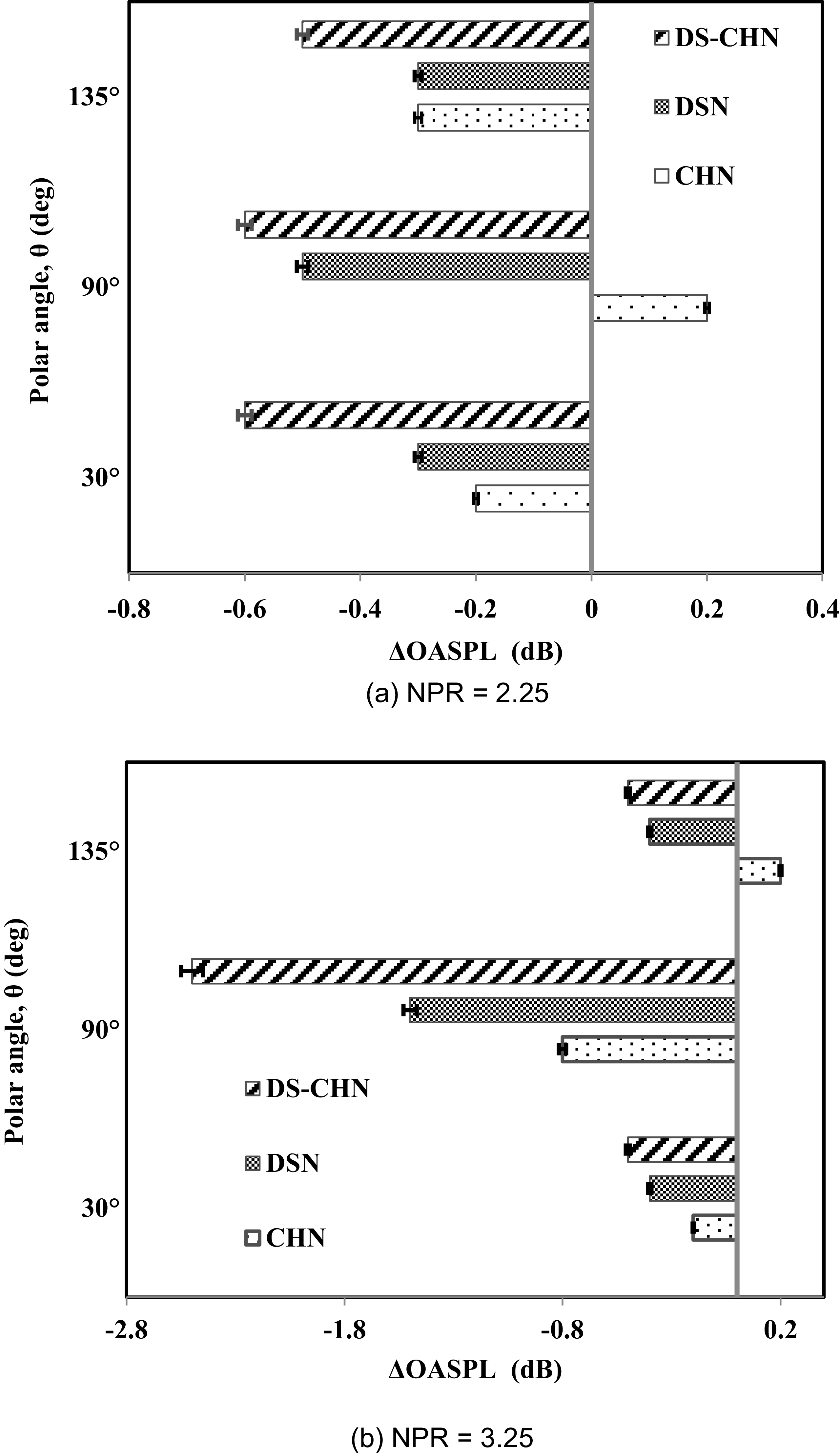
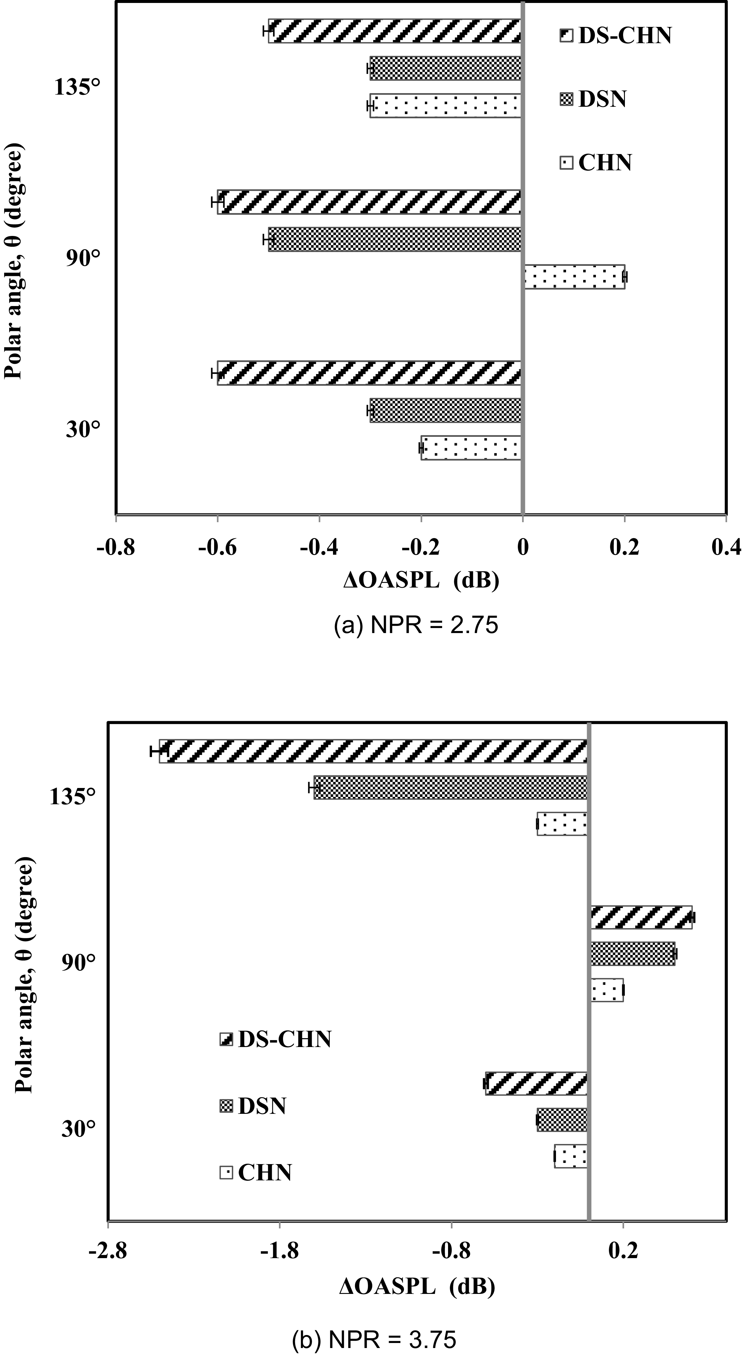
Comparison of difference in OASPL for design Mach number 1.4.

The development of high-strength shock cells and their subsequent interaction with instability waves establishes a sustained feedback loop [Reference Tam, Ahuja and Jones36]. This advancement is the primary cause of the distinct fundamental peak at both the sideline (90°) and upstream directions (135°). Harmonics exert minimal influence on the sound spectra of both nozzles at a 30° azimuth (Figures 15 and 16). The decrease in the intensity of screech tones from DS-CHN for both NPRs (5.75 and 6.75) over all three azimuths is minimal. The DS-CHN reduces noise intensity (OASPL) by 3.8 dB at NPR 5.75 and by 5.2 dB at NPR 6.75, as determined by the variation in OASPL at a 30° azimuth. Consequently, it is evident that DS-CHN significantly mitigates intense low-frequency mixing noise. At an angle of 135°, DS-CHN exhibits a decrease of approximately 0.8 dB (OASPL) when compared to the BSN for the NPRs 5.75 and 6.75. Conversely, at 90°, both NPRs (5.75 and 6.75) of DS-CHN demonstrate minimal noise reduction (OASPL), measuring less than 0.5 dB.
The variation in ΔOASPL for all examined nozzles, including the BSN, deflected seal (DSN), chevron (CHN) and hybrid flow control nozzle (DS-CHN), is compared simultaneously to evaluate the extent of noise reduction (Figures 17 and 18). For ease of comparison, BSN OASPL values are considered as zero decibels and the attenuation obtained for the modified nozzles as ± ΔOASPL of the BSN. For the examined design Mach numbers of lower NPRs (2.25 and 2.75) and DS-CHN attained a maximum noise reduction of approximately 0.5 dB across all measured azimuths. Likewise, DSN demonstrated a maximum attenuation of approximately 0.25 dB, which is less than that of DS-CHN. However, CHN’s effectiveness in reducing noise magnitude is inferior to both DSN and DS-CHN. The magnitude of noise reduction by the DS-CHN significantly improves over the other nozzles as the NPR rises (3.25 and 3.75). It achieved a maximum noise reduction of ∼2.5 dB (Md = 1.4 at 90° and Md = 1.8 at 135°) compared to the BSN. Furthermore, for the remaining observed polar angles, DS-CHN exhibits a noise reduction magnitude approaching 0.5 dB. Consequently, the hybrid flow control nozzle exhibits a superior reduction in noise magnitude compared to both the identified discrete flow control nozzles (DSN and CHN) and the BSN. Comparable trends were observed across the examined polar angles, even for the higher investigated NPRs. To ensure brevity, only two lower NPR values were evaluated and compared for each design Mach number.
Comparison of difference in OASPL for design Mach number 1.8.

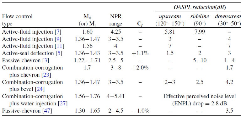
The subsequent paragraph is to explore the previously examined combined/hybrid flow control methods. Literature [Reference Tinney, Valdez and Murray23, Reference Powers and McLaughlin24, Reference Viswanathan, Krothapalli, Seiner, Czech, Greska and Jansen27] explored the combined flow control techniques, such as the corrugated seal-chevron, corrugated-bevel nozzle and corrugation with water for supersonic jet noise mitigation. The Mach numbers for the investigated design range from 1.30 to 1.67. All three studies indicated that combined flow control methods offer greater noise reduction than discrete techniques, such as chevron, bevel, corrugation and water injection. This finding supports similar results observed in the current hybrid flow control technique. Among the methods listed, the combination of a corrugated seal and chevron achieves the maximum reduction in OASPL, ranging from 1.7 dB to 2 dB. Despite operating at elevated design Mach numbers (1.4 and 1.8), current hybrid flow control methods delivered a significant reduction in OASPL compared to the previously investigated combined/hybrid flow control methods. For the design Mach numbers of 1.4 and 1.8, azimuth 30° (dominated by the mixing noise) alone reached a maximum OASPL reduction of 4.2 dB and 5.2 dB, respectively. Additionally, a significant reduction in shock-associated noise was observed and documented, including a maximum decrease of 2.8 dB in screech noise. Table 2 has been made to compare the reduction magnitude of jet noise and thrust penalty of the various flow control methods (active, passive and combination of flow control methods). Therefore, it can be asserted that the proposed DS-CHN nozzle exhibits relatively improved jet noise reductions compared to most discrete flow controls, such as chevron and deflected seal, and previous hybrid or combined flow control methods.
Far-field acoustic performance and thrust coefficient comparison for diverse flow control techniques

Table 2. Long description
A table comparing flow control types and their acoustic performance and thrust coefficients. The table has 8 rows and 6 columns. Column headers are Flow control type, M d (or M j), NPR range, C f, and OASPL reduction (dB) with subheaders upstream (120°–150°), sideline (90°), and downstream (30°–50°). Row 1: Active-fluid injection, 1.60, 4.25, -, 5.81, 7.99. Row 2: Active-fluid injection, 1.36–1.47, 3–3.5, -, 3, 4. Row 3: Active-fluid injection, 1.56, 4, -, 7, 7. Row 4: Active-seal deflection, 1.36–1.43, 3–3.5, +1.1%, 1.5, 2, 3. Row 5: Passive-chevron, 1.22–1.71, 2.5–5, -, 5–10, 1–4. Row 6: Combination-corrugation plus chevron, 1.7, 3–8, +2.0%, -, -, 1.7. Row 7: Combination-corrugation plus bevel, 1.36–1.47, 3–3.5, -, 2–3, 2.5, 4.2. Row 8: Combination-corrugation plus water injection, 1.56–1.76, 4–5.41, -, Effective perceived noise level (ENPL) drop = 2.8 dB. Row 9: Passive-chevron, 1.30–1.65, 2–4.5, -1.0%, -, -, 3.5.
3.3 Correlation methods for far-field recorded acoustic signals
The correlation techniques, particularly auto-correlation and cross-correlation, are employed to assess the acoustic features imprinted on the recorded jet noise signals. Individual pressure fluctuations are employed for the autocorrelation, while simultaneous measurements of pressure fluctuations captured by a microphone array are employed for cross-correlation functions. Both correlation approaches are implemented through MATLAB tools. The normalised autocorrelation and cross-correlation functions are derived from Equations 8 and 9. Both the BSN and DS-CHN nozzles are analysed and compared for design Mach numbers 1.4 (NPR = 2.25 and 6.25) and 1.8 (NPR = 2.75 and 6.75).
 \begin{align} R\left(\tau \right)={\langle P_{m}\left(t\right)P_{n}\left(t+\tau \right)\rangle \over \left\langle {P_{m}}^{2}\left(t\right) \right\rangle } \end{align}
 \begin{align} R_{mn}\left(\tau \right)={P_{m}\left(t\right)P_{n}\left(t+\tau \right) \over {P_{m}}^{2}\left(t\right)^{\frac{1}{2}}\left\langle {P_{n}}^{2}\left(t+\tau \right)\right\rangle ^{\frac{1}{2}}} \end{align}
Normalised autocorrelations of a BSN and DS-CHN of Mach 1.8 (NPR = 2.75).

Figure 19 illustrates the autocorrelations of the Mach 1.8 jet at four azimuthal angles: 30°, 60°, 90° and 135°. It is evident that under the zero-lag condition, the autocorrelation coefficient attains a value of one; this condition ensures simultaneous observations at four specified azimuths. The autocorrelation shape depicts the characteristics of temporal variation in the local pressure field, functioning as a waveform that signifies either turbulent structures or acoustic sources. Modifications in turbulent structure in such a way make the structure become less coherent that reduce the efficiency of noise radiation [Reference Tam, Viswanathan, Ahuja and Panda2, Reference Nikam and Sharma38]. Wave form of the autocorrelations of BSN at 30° and 60° are nearly analogous; however, 90° fall into a distinct class. The autocorrelation function at 90° accurately delineates fine-scale turbulence (i.e. smaller half-cone width). In addition to this, the half-widths of the two functions differ significantly.
The autocorrelation of large turbulence structure (i.e. mainly azimuth 30°) noise is marked by significantly deep negative peaks (∼0.5), which are twice (∼0.25) as profound as those seen in fine-scale turbulence (i.e. azimuth 90°). As identified deep negative peaks and broader half-widths are the intrinsic features of the large-scale turbulence structures, which are highly coherent in nature [Reference Tam, Viswanathan, Ahuja and Panda2]. Thus, the current identification also complements the two sources of acoustic turbulence mixing noise: fine-scale and large-scale. At 135°, the waveform for the BSN displays a comparatively larger half-cone width and an identical negative dip (∼0.5) in relation to the 30° azimuth. Also, no wiggles are present in the waveform. Over all, the DS-CHN waveform shows the reduced negative peak (∼0.25 at 30° and ∼0.35 at 135°) from all identified azimuths than the BSN. As identified, the lower amplitude of the negative peak at 30° azimuth for the DS-CHN indicates a reduced effect of acoustic radiation due to large-scale turbulent structures [Reference Nikam and Sharma38].
Figure 20 depicts the autocorrelation properties at an elevated NPR of 6.75. The negative peak for the BSN at a 30° azimuth attained 0.25, representing a 50% reduction compared to the peak magnitude observed by the BSN at an NPR of 2.75. The lower amplitude of negative peak corresponds with the diminished radiation intensity of large-scale turbulence noise [Reference Nikam and Sharma38]. In contrast, the DS-CHN waveform displays a coefficient magnitude nearly reaching zero and a significantly reduced half-cone width, directly correlating with the random fine-scale turbulence structures. The autocorrelation findings indicate that the DS-CHN breaks down large-scale turbulent structures into smaller ones by augmenting the mixing within the jet shear layer. It is anticipated that improved mixing will lead to a reduction in the convection velocity of modified turbulent structures. Consequently, fragmented turbulent formations with diminished convection velocity significantly restrict the intensity of noise radiation [Reference Tinney, Valdez and Murray23, Reference Nikam and Sharma38]. Likewise, in high supersonic and hypersonic flow, transitional and turbulent boundary layers predominantly contribute to the acoustic loading and fatigue experienced by the structural components of an aircraft. Elevated inlet turbulent intensity results in significant pressure fluctuations and facilitates a more rapid transition to turbulence, thereby increasing acoustic loading on the relevant surfaces [Reference Ritos, Drikakis and Kokkinakis45]. Moreover, the shock reattachment zone within the boundary layer generates the steepest pressure gradients, which consequently contribute to the acoustic loading [Reference Ritos, Drikakis, Ioannis and Kokkinakis46]. Autocorrelation study for the Mach 1.4 jet was conducted at two extreme NPRs (2.25 and 6.25); the resulting waveform patterns closely resemble those from the Mach 1.8 jet, with only a slight change in autocorrelation coefficients.
Normalised autocorrelations of a BSN and DS-CHN of Mach 1.8 (NPR = 6.75).

Figure 21 illustrates the cross-correlation between the BSN and DS-CHN for the NPRs of 2.75 and 6.75, respectively. Measurements from 30°, 60°, 90° and 135° angles are used for cross-correlation. R11 uses 30°−30° inputs as a reference, while R12, R13 and R14 calculated correlation outcomes from two independent signal inputs (30°−60°, 30°−90° and 30°−135°). In contrast to autocorrelation, cross-correlation peaks with a temporal delay, with the exception of R11. At NPR 2.75, BSN’s R12 exhibits a slight positive time shift and lower peak magnitude (0.75) than R11. The cross-correlation results for R13 and R14 are entirely out of phase with R11, exhibiting clear negative lags while keeping the peak value consistent at 0.7. For the same NPR (2.75) the DS-CHN exhibits two wave forms, R12 and R13 which are in phase with R11, while facing different positive lags. Still, R14 is out of phase with R11, with the reduced peak (∼0.5) and a lesser negative lag than the BSN. The fluctuation in the peak amplitude of the cross-correlation coefficient with respect to time delay depends upon the phase difference of the signal recorded in the far-field region. In-phase signals exhibit positive peak amplitude, while out-of-phase signals decline below zero and approach zero as they become uncorrelated [Reference Nikam and Sharma38]. Similarly, the cross-correlation for the higher NPR of 6.75 was investigated. Figure 21d illustrates that nearly all three waveforms (R12, R13 and R14) are distorted, displaying a significantly reduced peak coefficient of approximately 0.25. The reduction in the peak coefficient is relevant to the diminished intensity of its acoustic radiation as it becomes less coherent (i.e. fine-scale turbulence). Furthermore, R11 shows a narrower half-cone width when compared to the BSN of R11. Consequently, these advancements clearly demonstrate that the hybrid flow control nozzle effectively modifies and mitigates the radiation intensity of the primary acoustic sources associated with the complex supersonic jets.
Normalised cross-correlations of a BSN and DS-CHN of Mach 1.8.

3.4 Crackle jet noise identification for far-field acoustic signals
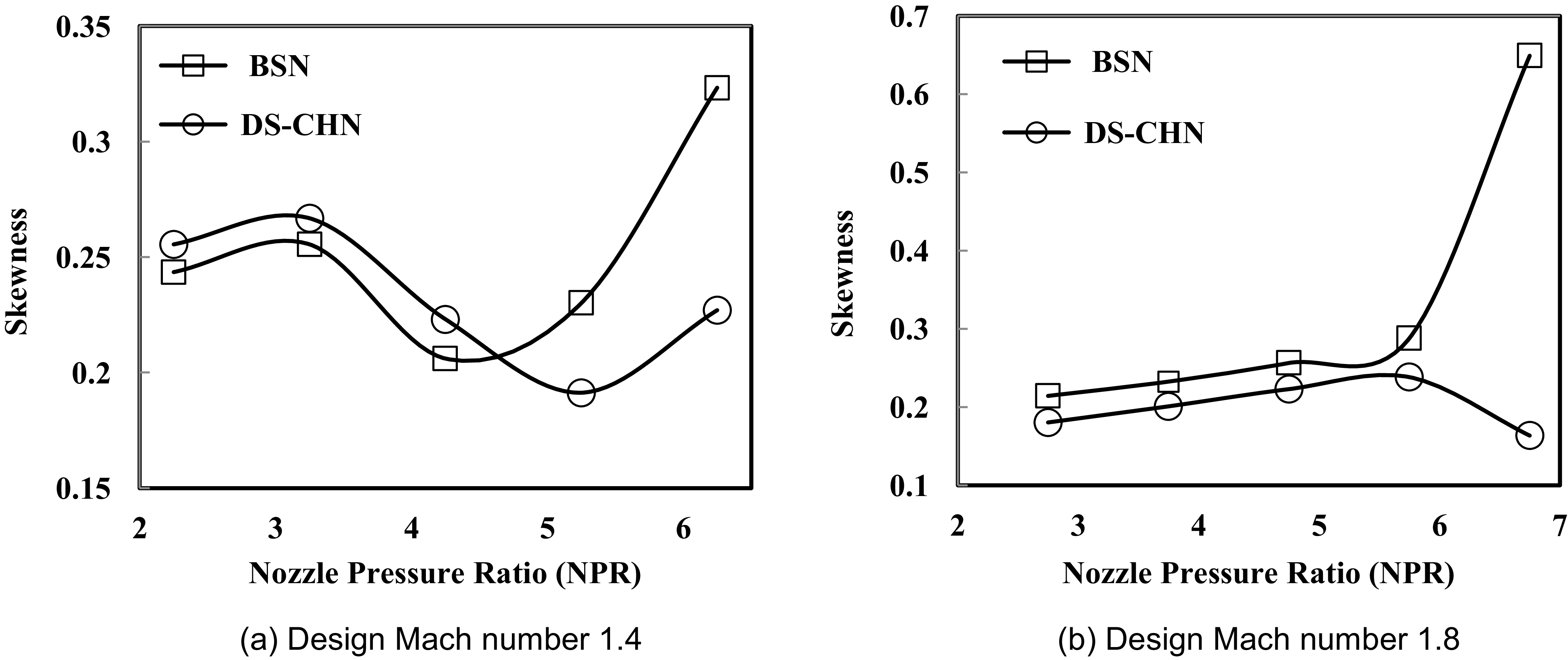
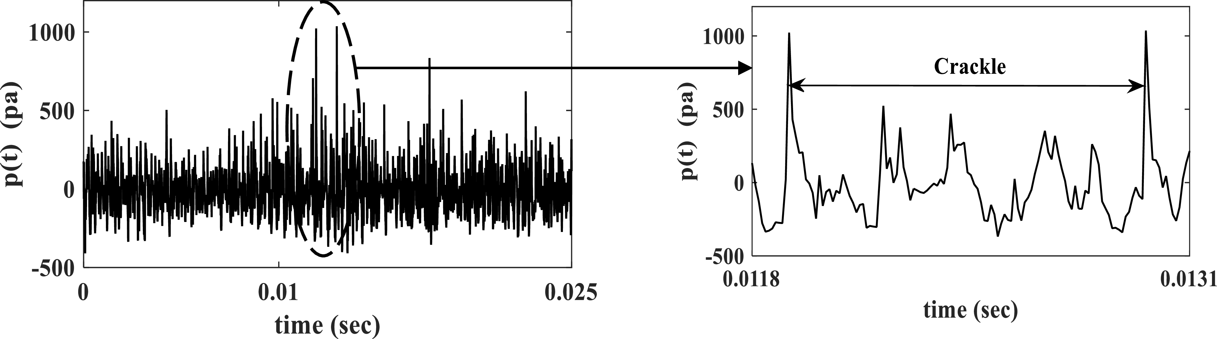
Crackle is acknowledged as an annoying and subjectively distinct component of jet noise, first outlined by Ffowcs Williams et al. [Reference Williams, Simson and Virchis42], who defined crackle as `spasmodic bursts of a rasping, fricative sound’. The crackle is shown to be the sharp shock-like compressive waves that sometimes occur in the wave form. The accompanying expansion waves are always gradual and less intense. Hence, the compressive parts of the recorded time-series signals have a distinct shape, being composed of a sharp rise followed by a gradual expansion [Reference Krothapalli, Venkatakrishnan and Lourenco43, Reference Baars, Charles and and.44]. Finally, authors have concluded that noise signals with a normalised skewness less than 0.3 do not crackle, whereas those with skewness in excess of 0.4 crackle distinctly [Reference Williams, Simson and Virchis42]. Furthermore, it was indicated that the intensity of skewness is dependent on both jet velocity and observation angle. A significant level of crackle is observed in the downstream direction (i.e. 30° to 40°), aligning with the orientation of predominant low-frequency jet mixing noise [Reference Williams, Simson and Virchis42, Reference Krothapalli, Venkatakrishnan and Lourenco43]. Consequently, in the present research, skewness values are computed and compared for both design Mach numbers (Md
= 1.4 and 1.8). Calculations were performed for all examined NPRs and azimuths (30°, 60°, 90° and 135°); however, only the skewness values for the 30° azimuth are presented and analysed. The skewness is calculated using Equation 10, where σ is standard deviation of the pressure signal, E is the expected value and p(t) and
 $\overline{{\rm P}({\rm t})}$
is the pressure signal and its mean value.
 \begin{align}{\rm Skewness}={E\left[\left({\rm P}\left({\rm t}\right)-\overline{{\rm P}({\rm t})}\,\right)^{3}\right] \over \sigma ^{3}} \end{align}
Fluctuating pressure magnitudes from full 0.5-second signals are utilised to compute the skewness for both design Mach numbers. Figure 22 presents a comparison of the calculated skewness factor for the BSN and the DS-CHN. It has been noted that, for both design Mach numbers associated with the maximum operational NPRs (6.25 at Md = 1.4 and 6.75 at Md = 1.8), the BSNs attain a skewness factor that markedly surpasses the crackle threshold of 0.3. In addition, it is observed that the magnitude of the crackle increases with increasing jet velocity [Reference Williams, Simson and Virchis42, Reference Krothapalli, Venkatakrishnan and Lourenco43]. The skewness factors for the remaining identified NPRs at both design Mach numbers consistently remain below 0.3. This signifies that both BSNs are generating crackle jet noise at the maximum operational NPRs. At the same time, for the highest NPRs, hybrid flow control nozzles are exhibiting skewness magnitudes that are significantly below the crackle threshold, with recorded values of 0.22 at NPR 6.25 and 0.16 at NPR 6.75. The proposed novel hybrid nozzle with flow control effectively mitigates intense crackle noise for both examined design Mach numbers. Additionally, the shock structures attributed to the crackle are depicted in Figure 23, particularly for the NPR of 6.75, which aligns with the design Mach number of 1.8.
Skewness factor comparison for both the BSN and DS-CHN at 30° azimuth.

Time-series pressure signal of a BSN for the NPR of 6.75.

4.0 Conclusion
The proposed DS-CHN (active deflecting seal with passive chevron petals) was evaluated at design Mach numbers of 1.4 and 1.8 for aeroacoustic performance. The Schlieren images demonstrate that the proposed DS-CHN reduces the shock cell length and supersonic core jet width while increasing the shear layer thickness across all investigated NPRs. Far-field acoustic measurements were also performed for both design Mach numbers to evaluate noise radiation features. Jets leaving the nozzle (DS-CHN and BSN) exhibit harmonic-dominated SPL spectra at the lower NPRs. In contrast, harmonics have minimal impact at higher NPRs. The tested NPRs for the Mach-1.4 nozzle varied between 2.25 and 6.25. Both the BSN and DS-CHN exhibit a fundamental peak at St = 0.22. In comparison to the BSN, the DS-CHN diminished screech noise by 2.8 dB at 90° (NPR = 2.25), 2.5 dB at 30° (NPR = 3.25) and ∼ 3 dB at 135° (NPR = 4.25 and 5.25). Thus, a reduction in harmonic intensity and screech noise at higher NPRs is linked to disrupted acoustic feedback due to the formation of a convoluted shear layer. The DS-CHN demonstrated a considerable reduction in dominating low-frequency mixing noise magnitude in the downstream direction (30°), varying from 0.5 to 4 dB in relation to OASPL, when contrasted with the BSN.
The Mach-1.8 nozzles were evaluated at NPRs ranging from 2.75 to 6.75. Both the BSN and DS-CHN exhibit jets that display a fundamental peak at St = 0.19. In comparison to the BSN, the DS-CHN shows a reduction in screech noise across all identified NPRs; however, this reduction is slightly less significant than that observed in the Mach-1.4 DS-CHN. The DS-CHN demonstrates greater effectiveness than the BSN in diminishing noise generated by large-scale vortices. The OASPL demonstrates a decrease in low-frequency noise levels, showing a reduction of 0.5 dB at NPR 2.75 and 5.2 dB at NPR 6.75. The findings indicate that the identified hybrid flow control nozzle effectively mitigates the predominant low-frequency mixing noise for both examined design Mach numbers. Additionally, the identified DS-CHN moderately reduces shock noise for both examined design Mach numbers (1.4 and 1.8). The cross-correlation results of the far-field input show three non-identical time lags, indicating the existence of three separate acoustic sources. In the same way, the autocorrelation analysis is able to identify three different waveforms, which characterise the types of acoustic sources: low-frequency mixing noise, high-frequency noise and screech tone. In addition, DS-CHN experiences the reduced cross and autocorrelation coefficients for the two identified NPRs that reveal the reduced coherence and radiation intensity. Thus, the correlation techniques complement each other to improve jet acoustics understanding and show that the hybrid flow control nozzle positively alters and reduces the radiation intensity of the complex supersonic jets’ acoustic sources. Finally, the degree of skewness indicates that the BSNs for both examined design Mach numbers produce crackle jet noise at the peak operating NPRs of 6.25 and 6.75. In contrast, the suggested nozzles with hybrid flow control significantly reduced the crackling noise at the same NPRs.
Acknowledgements
The authors acknowledge the grant provided by the Aeronautics Research & Development Board, Ministry of Defense, Government of India for the work presented in this paper under their Grant-in-Aid Scheme (Grant number ARDB/01/1031969/M/I) during the years 2020–2023. The authors also express their gratitude to Gas Turbine Research Establishment, Government of India for their collaboration during the work.
Financial support
This research work is supported by grants from the Aeronautics R&D Board (AR&DB), Defence Research and Development Organisation (DRDO), and Ministry of Defence, Government of India. The authors extend their gratitude to AR&DB for their invaluable financial support. Grant sanction order no. ARDB/01/1031969/M/I.
Competing interests
The author(s) declare that they have no competing interests.