Introduction
Titanium (Ti) and its alloys have been widely used as biomedical materials and have found numerous applications as artificial bones and as various types of biocompatible implants due to their highly beneficial chemical, physical, mechanical, and physiological properties. Especially, their chemical resistance upon contact with fluids and tissue encountered in the human body make them suitable implant materials because they meet numerous selection criteria. Moreover, Ti being a light metal possesses required properties, such as good ductility, high tensile modulus, fatigue strength, as well as an elastic modulus comparable with that of the human bones. An appropriate surface treatment is required to enhance the bone-bonding capacity of Ti implants.[Reference Kim, Miyaji, Kokubo and Nakamura1–Reference Tanaka, Tobinatsu, Maruyama, Tanaki and Jerkiewicz14] For instance, apatite surface layers are often used in Ti implants to provide their bioinert surfaces with bioactive materials, such as apatite or metaphosphate-containing glass-ceramics. These layers (also referred to as coatings) are typically prepared using plasma spraying at very elevated temperatures,[Reference Ducheyne, Raemdonck, Heughebaert and Heughebaert4, Reference Thomas, Kay, Cook and Jarcho5] although the process is known to alter the crystal structure of the metal or alloy, bringing about diminished biocorrosion resistance, cracking the surface layer, as well as introducing other structural defects. Alternative methods of preparing coatings and fine-tuning their interfacial properties are laser deposition,[Reference Bagratashvili, Antonov, Sobol, Popov and Howdle6] sol-gel dipping,[Reference Lee and Aoki7, Reference Li, Groot and Kokubo8] electrophoresis,[Reference Ducheyne, Radin, Heughebaert and Heughebaert9, Reference Gottlander, Johansson, Wennerberg, Albrektsson, Radin and Ducheyne10] or soaking in an alkaline solution,[Reference Tanaka, Aonuma, Hirose and Tanaki11–Reference Tanaka, Tobinatsu, Maruyama, Tanaki and Jerkiewicz14] etc.
In the case of Ti-based materials, biocompatibility improvement can be achieved by applying many different surface treatment techniques. However, electrochemical surface treatment methods offer some advantages, such as relative simplicity and low application cost. For instance, anodization (anodic formation of a surface oxide) is the most common surface treatment technique that forms a protective layer on Al, Ti, and valve metals. Because an anodic oxide layer possesses a low electrical conductivity as compared with that of electrolytes or bulk, metallic Ti, there is a significant potential drop across the oxide layers on the metallic substrate. This potential drop gives rise to a strong electric field across the oxide film, which then drives the migration of Ti4+ and O2− ions through the oxide layer. The ions that are driven through the anodic oxide layer by an externally applied electric field promote the growth of anodic oxide. As long as the electric field is strong enough, the ions will be driven through the anodic oxide film and this film will continue to grow during anodization. Many researchers observed that there is usually a linear relationship between the oxide film thickness and the applied voltage.[Reference Ohtsuka and Nomura15] Yet, as the applied potential increases, the oxygen evolution reaction takes place on the Ti surface during its anodization. Thus, the correlation between the oxide layer thickness and applied anodic potential is not precisely proportional. This linear relationship keeps the limit of dielectric breakdown of the anodic oxide below 100 V; the latter value depends on the electrolyte and parameters of the process.[Reference Kim and Ramaswamy16] When the applied potential is higher than the dielectric breakdown potential, the strong electric field that established across the anodic oxide film causes it to break down and proceeds ahead of the growth of pores. Elsewhere, it was reported that a porous layer on Ti is obtained when it is anodized in 1.0 M H2SO4 solution with direct current (DC) voltage, V DC, being in the 90–180 V range.[Reference Yang, Uchida, Kim, Zhang and Kokubo17] The authors also reported the occurrence of interfacial discharge manifested by sparking, when the applied potential was higher than 105 V. Although no apatite formed on the porous oxide layer which anodically oxidized without spark discharge in the simulated body fluid (SBF), the apatite formed on the porous layer anodized with simultaneous sparking in 1.0 M aqueous H2SO4. However, there is a possibility of damage to the surface and/or the substrate due to spark discharge during anodization of Ti. Therefore, it is necessary to establish the fabrication conditions in order to prepare the porous layer on Ti without spark discharge during anodization.
Shih et al. investigated the impact of nano-Ti hydride formation of the porous TiO2 layer obtained by anodization in 5.0 M NaOH solution.[Reference Shih, Lin, Liu, Chen, Chen and Ou18] A nano-Ti hydride was formed upon cathodic polarization in 1.0 M H2SO4 solution prior to anodization. The anodic thick porous TiO2 layer was obtained on Ti with cathodic treatment. They suggested the presence of TiH2 phase on Ti before anodization plays a significant role in preparing a thick porous TiO2 layer. The same data are conveyed by our group when a porous layer was obtained on the Ti surface by immersion of Ti in a concentrated alkaline solution.[Reference Tanaka, Aonuma, Hirose and Tanaki11–Reference Tanaka, Tobinatsu, Maruyama, Tanaki and Jerkiewicz14] Recently, we showed that the formation of an absorbed hydrogen and/or hydride layer during immersion is a key factor to produce porous layers on Ti.[Reference Tanaka, Fukushima, Nakamura, Tanaki and Jerkiewicz19] In the previous report, we observed hydrogen charging before anodization of Ti created a dense anodic oxide layer on which a porous layer can be obtained at a lower voltage without spark discharge in 1.0 M aqueous H2SO4. In our previous work, an anodic oxide layer was formed on the hydrogen-charged Ti and had a lower charge carrier density.[Reference Tanaka, Fukushima, Nakamura, Tanaki and Jerkiewicz19] The diminished charge carrier density caused by hydrogen ingress before anodization can decrease the oxide layer conductivity and creates favorable conditions for its electrical breakdown, which stimulates the development of pores. Hrapovic et al. prepared an anodic oxide film on Ti in NH4BF4 solution by alternating current (AC) electrolysis.[Reference Hrapovic, Luan, Amours, Vatankhah and Jerkiewicz20] The coloration of the anodized oxide layer on Ti can be reversed by adjusting the anodizing potential.[Reference Jerkiewicz, Zhao, Hrapovic and Luan21] They also reported that the oxide film obtained with AC electrolysis had higher corrosion resistance in the SBF solution compared with that obtained by DC electrolysis.[Reference Zhao and Jerkiewicz22, Reference Drunen, Zhao and Jerkiewicz23]
This work focused on AC electrolysis as a forming method of a nanosized porous oxide film on a Ti surface. In the case of AC electrolysis, Ti is polarized repeatedly in positive and negative for a short time depending on the frequency. The anodic oxide film grew on the surface when the Ti was anodically polarized. In the case of high voltage, the oxygen evolution reaction also proceeded as a side reaction of anodic oxide film formation. On the other hand, the hydrogen evolution reaction (HER) only occurred in 1.0 M aqueous H2SO4 solution when Ti was cathodically polarized during AC electrolysis. Part of the electrochemically reduced hydrogen entered Ti and formed an absorbed hydrogen layer near the surface. The absorbed hydrogen layer led to a decrease of anodization potential for producing a porous oxide layer.[Reference Tanaka, Fukushima, Nakamura, Tanaki and Jerkiewicz19] Therefore, we demonstrated the possibility that nanosized porous oxide layers can be obtained on a Ti surface using AC electrolysis in a short period of time and without spark discharge.
Materials and methods
Ti sheets (Nilaco Co., Ltd., 99.5% purity) having a thickness of 1.0 mm were employed in electrochemical measurement and scanning electron microscopy (SEM). The Ti sheet was cut into a 10 mm square and then was spot-welded to a Ti wire (Nilaco Co., Ltd., 99.5% purity, 0.5 mm diameter) for electrical contact. The Ti wire was insulated with a shrinkable Teflon tube or Teflon tape. The Ti specimen was mechanically polished with 1200 grade silicon carbide grit paper. The specimen was cleaned (degreased) in hot acetone under reflux for 240 min, air dried and rinsed with de-ionized water (Millipore, Milli-Q water purification system). Finally, the specimen was etched in an aqueous solution of HF (2.0% vol.) and HNO3 (4.0% vol.) at ambient temperature for several seconds, and then rinsed thoroughly with de-ionized water.
Electrolysis of Ti was conducted in 1.0 M H2SO4 solution using an AC stabilized power supply (Kikusui Electronics Co., Ltd., model PCR500 M, 1.0–270 V, 40–500 Hz). The sulfuric acid solution was prepared using analytical-grade chemicals (Kanto Chemical Co., Inc.) and de-ionized water. The solution temperature was maintained constant at 303 K using a water bath (Yamato Scientific Co. Ltd., model BF400). A large platinum foil (Nilaco Co., Ltd., 99.98% purity) was used as a counter electrode. The distance between the Ti and the counter electrode was kept constant at 30 mm. The AC electrolyzing time was 60 s. The frequency of the AC electrolyzing process was kept constant at 60 Hz. After electrolysis, the Ti specimen was washed with de-ionized water and air dried. The surface topography was studied by SEM (Hitachi Co., Ltd., model S-2380N or Elionix Co., Ltd., model ERA-8900FE).
Results and discussion
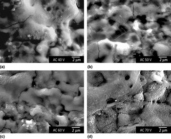
Figures 1(a)–1(d) show SEM images of four Ti specimens after AC electrolysis at AC voltage, V AC = 40, 50, 60, and 70 V, respectively, and AC frequency, f AC = 60 Hz in 1.0 M H2SO4 solution at 303 K. In this work, V AC is indicated by the root mean square (RMS) value, i.e. effective value. As seen from Figs. 1(a)–1(d), there is no porous layer on the surface when the V AC is below 70 V. When AC electrolysis is adapted to make a porous layer, hydrogen and oxygen gas evolutions were observed on the Ti surface. In addition, the spark discharge begins to start above V AC = 40 V. During AC electrolysis of Ti at a high voltage, vigorous generation of hydrogen and oxygen gases occurs on the Ti surface. As a result, the Ti specimen is enveloped by a gaseous layer containing both hydrogen and oxygen. Since the gaseous envelope plays the role of an electrical insulator, a strong electric field develops between the Ti substrate, including the oxide film, and the gaseous layer (envelope). When the applied V AC is above 40 V, the electric field overcomes the gas layer and, as a consequence, spark discharge is observed on the Ti specimen. As shown in Fig. 1, there were a lot of large pits or craters above 1000 nm in diameter on the Ti surface. These large pits or craters may be caused by spark discharge during AC electrolyzing.
SEM images of the surface of Ti after AC electrolysis at V AC = (a) 40, (b) 50, (c) 60, and (d) 70 V, respectively, and f AC = 60 Hz in 1.0 M aqueous H2SO4 solution at 303 K for 60 s.

The SEM image also indicated the formation of many nanosized pores at V AC = 70 V, although the large pits and craters still existed on the Ti surface [Fig. 1(d)]. In the case of DC anodization, when the V DC is above 150 V and the process proceeds with hydrogen ingress before the anodization, a porous layer on the Ti surface was obtained in 1.0 M aqueous H2SO4 solution.[Reference Tanaka, Fukushima, Nakamura, Tanaki and Jerkiewicz19] This is because a high electric field occurs within the metal/film and film/electrolyte interfaces, and then a dielectric breakdown of the oxide layer takes place under the same conditions. If the oxide layer is unable to withstand such a strong electric field, then dielectric breakdown occurs and produces pores in the oxide film. As shown in Fig. 1(d), the formation of a nanosized porous layer was observed on the Ti surface when the V AC is high, V AC = 70 V. This result implies that the same breakdown phenomena occur in the oxide film during AC electrolysis. Although the formation of a nanosized porous layer is produced at a lower voltage (V AC = 70 V) compared with DC anodization (V DC = 150 V), it is suggested that the dense oxide layer is more easily formed on the Ti surface by AC electrolysis than by DC anodization. In the case of AC electrolysis, the hydrogen absorption reaction occurs on the cathodically charged Ti surface and the dense anodic oxide layer is formed when the Ti is anodically polarized.[Reference Tanaka, Fukushima, Nakamura, Tanaki and Jerkiewicz19] Therefore, the breakdown potential of the dense oxide layer produced during AC electrolysis may be lower than that of the usual anodic oxide obtained by DC anodization. However, the nanosized porous layer does not grow enough and the damage to the Ti substrate due to spark discharge was also observed on the Ti surface. These results suggest that AC electrolysis does not adapt to the formation of a nanosized porous oxide layer without some additional mechanism.
Since the spark discharge is caused by the adjacent gas layer which consists of gaseous hydrogen and oxygen evolved from the Ti surface, spark discharge can be stopped by the inhibition of the gas evolution reaction during AC electrolysis in the same conditions. A high anodic potential is needed for the formation of the nanosized porous oxide layer on the Ti surface so that the oxygen gas evolution reaction cannot be inhibited during electrolysis. On the other hand, the HER is not needed for the anodization of Ti. In addition, a large amount of hydrogen absorption into the Ti substrate leads to hydrogen embrittlement because Ti easily forms Ti hydride with absorbed hydrogen. However, we reported that hydrogen charging before DC anodization reduced the carrier density in the oxide layer on Ti.[Reference Tanaka, Fukushima, Nakamura, Tanaki and Jerkiewicz19] The anodic oxide film obtained with hydrogen charging was dense enough that a strong electric field was established between the Ti substrate and the anodic oxide surface, resulting in a dielectric breakdown of the oxide film without spark discharge. Therefore, in order to form a nanosized porous layer on the Ti surface by AC electrolysis, hydrogen absorption is needed in a limited amount. It is a very important factor that a minimum amount of absorbed hydrogen exists near the surface to prevent hydrogen embrittlement of the Ti substrate.
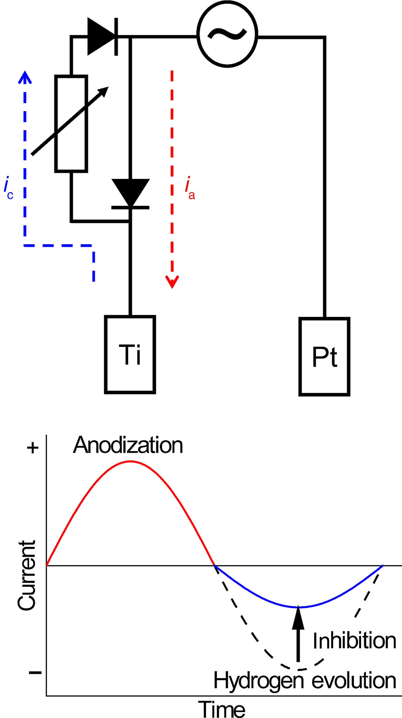
In order to inhibit the hydrogen gas evolution reaction during AC electrolysis, we used a special electrical circuit which consists of a variable resistor and two diodes, and the schematic diagram is shown in Fig. 2. When Ti is anodically polarized during AC electrolysis, the electric current (i a) flows directly from a counter electrode (Pt) to Ti. On the contrary, when Ti is cathodically polarized, the cathodic current (i c) flows to Pt via a variable resistor from Ti. Therefore, the HER on Ti can be inhibited by using a special electrical circuit. In this circuit, the i c, i.e. the rate of HER can be controlled with a resistance (R) value (0.6 to 1.0 kΩ). Using this special electrical circuit, an asymmetric AC current can be applied to Ti, as illustrated in Fig. 2.
Schematic diagram of the special electric circuit and the asymmetric AC current for Ti.

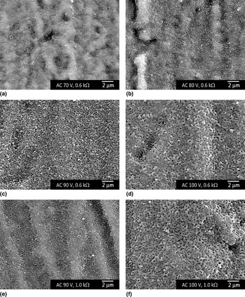
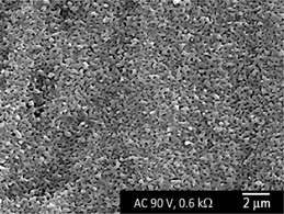
Figures 3(a)–3(d) display SEM images of four Ti specimens after asymmetric AC electrolysis using the special electrical circuit at V AC = 70, 80, 90, and 100 V, respectively, and R = 0.6 kΩ, and f AC = 60 Hz in 1.0 M H2SO4 solution at 303 K. When not using the special electrical circuit for AC electrolysis, the vigorous spark discharge on Ti surface was due to gas evolution as mentioned above. Therefore, the higher V AC used to obtain the nanosized porous oxide layer cannot be applied to Ti. However, it is possible to apply a higher V AC such as 100 V using the special electrical circuit. As shown in Figs. 3(a)–3(d), the nanosized porous oxide layer started to form on the Ti surface at V AC = 70 V and is well developed above V AC = 90 V. As mentioned before, because the V AC is defined by the RMS value, the peak voltage corresponds to 127 V in the case of V AC = 90 V. We reported that the nanosized porous oxide layer was completely developed at V DC = 130 V under the same conditions on the hydrogen-charged Ti surface.[Reference Tanaka, Fukushima, Nakamura, Tanaki and Jerkiewicz19] It is noted here that the roundish shape of the nanosized pores, formed on the Ti surface at V AC = 90 V and R = 0.6 kΩ [Fig. 3(c)], is similar but the size is rather small in comparison with those in previous reports. Although there are some differences on the morphology of the nanosized porous oxide films on Ti, basically the microporous oxide layer was obtained by the same formation mechanism in the case of DC anodization with hydrogen ingress before anodization. Namely, when Ti is cathodically polarized in 1.0 M H2SO4 solution, the HER takes place according to the following mechanism; the process is accompanied by hydrogen absorption (ingress):
 $$H^ + + e^-\to H_{{\rm OPD}}\;({\rm Volmer \, reaction})$$
 $$H_{{\rm OPD}} + H^ + + e^-\to H_2\;({\rm Heyrovski \, reaction})$$
 $$H_{{\rm OPD}} + H_{{\rm OPD}}\to H_2\;({\rm Tafel \, reaction})$$
 $$H_{{\rm OPD}}\to H_{{\rm SS}}$$
 $$H_{{\rm SS}}\to H_{{\rm abs}}$$
SEM images of the surface of Ti after asymmetric AC electrolysis at (a) V AC = 70 V and R = 0.6 kΩ, (b) V AC = 80 V and R = 0.6 kΩ, (c) V AC = 90 V and R = 0.6 kΩ, (d) V AC = 100 V and R = 0.6 kΩ, (e) V AC = 90 V and R = 1.0 kΩ, and (f) V AC = 100 V and R = 1.0 kΩ, respectively, and f AC = 60 Hz in 1.0 M aqueous H2SO4 at 303 K for 60 s.

Thereby, the over-potentially deposited hydrogen (H OPD), which is an intermediate of the HER, exists on the electrode surface [Eq. (1)].[Reference Conway and Jerkiewicz24–Reference Qian, Conway and Jerkiewicz27] The adsorbed HOPD has a limited lifetime and the HER proceeds following one of the subsequent steps, namely the Heyrovski reaction or the Tafel reaction [Eqs. (2) and (3)]. It can also undergo interfacial transfer (an alternative process to the HER) to a subsurface state creating a subsurface hydrogen (H ss) species [Eq. (4)]. The H ss species can then undergo transfer into the bulk of Ti and become absorbed hydrogen (H abs) [Eq. (5)]. The amount of H abs determines whether a solid-state hydrogen solution (α phase) develops or hydride forms (large amounts of H abs); in the latter case precipitation of Ti hydride within the metallic Ti host is observed.
When Ti is anodically polarized in 1.0 M H2SO4 solution, the growth of an anodic oxide layer is driven by the migration of O2– ions towards the inner metal/film interface and that of Ti4+ ions from metallic Ti to the outer film/electrolyte interface. A strong electric field is also present within the metal/film and film/electrolyte interfaces. Dielectric breakdown occurs when a strong electric field overcomes the oxide layer, resulting in the formation of pores. Because such dielectric discharges can happen at any location and any time, numerous pores develop, and their assemblies generate a three-dimensional porous structure. Especially, a more compact oxide layer is obtained after hydrogen charging so that the dielectric breakdown potential of oxide film becomes lower, resulting in the formation of a nanosized porous oxide layer at a lower potential.[Reference Tanaka, Fukushima, Nakamura, Tanaki and Jerkiewicz19]
In the case of DC anodization in the same conditions, the formation potential of a microporous layer on Ti is about 150 V.[Reference Tanaka, Fukushima, Nakamura, Tanaki and Jerkiewicz19] We determined that this formation potential of the nanosized porous layer needs to be lowered by about 20 V when the Ti is cathodically treated for 30 min before anodization.[Reference Tanaka, Fukushima, Nakamura, Tanaki and Jerkiewicz19] This cathodic treatment plays an important role to decrease the formation potential of the anodic porous layer. In the case of asymmetric AC electrolysis, Ti is cathodically polarized for a very short time. In this short period of time, the HER proceeds on the Ti surface and a part of reduced hydrogen enters the Ti surface. As a result, a very thin hydrogen absorbed layer may be formed near the Ti surface. This hydrogen absorbed layer leads to the growth of the compact Ti oxide layer when Ti is anodically polarized during another short period of time. The produced compact oxide layer cannot withstand the strong electric field within the metal/film and film/electrolyte interfaces. Therefore, the formation potential of asymmetric AC anodization is lowered in comparison with DC anodization.
The amount of the absorbed hydrogen on the Ti surface can be controlled by the variable resistance in the special electrical circuit. In order to investigate the influence of the R value in the special electrical circuit on the formation of a nanosized porous layer on the Ti surface, we conducted asymmetric AC polarization by changing the R value in the same conditions. Figures 3(c)–3(f) show SEM images of four Ti specimens after anodization at V AC = 90 and 100 V, respectively, and R = 0.6 and 1.0 kΩ, respectively, and f AC = 60 Hz in 1.0 M H2SO4 solution at 303 K. As shown in Fig. 3(e), a nanosized porous layer on Ti is not developed enough when the R value is 1.0 kΩ at V AC = 90 V. Decreasing the R value to 0.6 kΩ led to the development of pores on the Ti surface [Fig. 3(c)]. Decreasing the R value in the special electrical circuit means an increase of the hydrogen evolution current during the asymmetric AC electrolysis. Thus, the amount of absorbed hydrogen on the Ti surface might increase. The SEM image implied that the formation of a nanosized porous layer is affected by the R value, in other words, the absorbed hydrogen. Zhao et al. reported the morphology, chemical composition, and electrochemical characteristics of an anodic oxide layer prepared by AC electrolysis in aqueous NH4BF4 solution.[Reference Zhao and Jerkiewicz22] They indicated that the obtained Ti oxide layer revealed an enhanced corrosion resistance in the SBF solution. Hrapovic et al. indicated that the anodic film obtained by AC electrolysis in aqueous NH4BF4 solution showed higher activity towards the HER rather than Ti in aqueous H2SO4 solution.[Reference Hrapovic, Luan, Amours, Vatankhah and Jerkiewicz20] These behaviors imply that the absorbed hydrogen caused by AC polarization will influence the formation and the property of anodic oxide films. Figures 3(d) and 3(f) display the Ti surface after asymmetric AC electrolysis at V AC = 100 V in 1.0 M H2SO4 solution. These images indicated that a well-developed nanosized porous layer is obtained regardless of the R values of the special electrical circuit. Because an increase of V AC means an increase in the hydrogen current, the amount of absorbed hydrogen might increase at the Ti surface and a compact oxide layer might be formed when Ti is anodically polarized for a short time. At the same time, a dielectric breakdown of the oxide film due to the strong electric field proceeds under the same conditions, resulting in the formation of a nanosized porous layer.
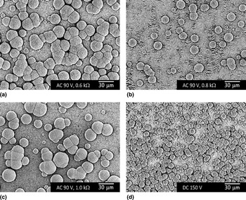
The bioactivity of materials is often examined by the growth of a bone-like apatite on their surfaces in SBF.[Reference Kokubo and Takadama28] In order to investigate the in vitro bioactivity of the asymmetric AC anodized Ti, an SBF solution was prepared by following our previous work,[Reference Iwata, Lee, Tsunakawa, Tokuoka and Kawashima29, Reference Iwata, Lee, Tokuoka and Kawashima30] and then the anodized Ti was soaked in the SBF at 309.5 K for 336 h. The soaking test results are shown in Figs. 4(a)–4(d). The SEM images demonstrate the surface of the asymmetric AC anodized Ti with the special electrical circuit and DC anodized Ti. There are precipitations of apatite, which have a characteristic spheroidal feature, on the anodized Ti surface irrespective of the R value of the special electric circuit [Figs. 4(a)–4(c)]. Similarly, the spheroidal precipitates existed on the surface of the DC anodized Ti [Fig. 4(d)]. These results implied the ability of apatite formation on the asymmetric AC anodized Ti surface is the same as that of the DC anodized surface. However, the size and the number of apatite precipitations are different between the asymmetric AC polarization and the DC polarization. Xiao et al. reported that apatite precipitation on the Ti surface significantly depends on the number of Ti-OH groups which are created by chemical treatment.[Reference Xiao, Tsuru, Hayakawa and Osaka31] The surface hydroxyl groups such as Si-OH, Ti-OH, and so on are known as effective inducers of apatite nucleation.[Reference Kasuga, Kondo and Nogami32, Reference Kokubo, Kim and Kawashita33] Depending on the pH of the aqueous solution, the Ti-OH groups can have positive or negative charges.[Reference Ma, Li, Hu, Chen and Hu34] In the case of SBF, the Ti-OH groups carry negative charges, which then attract Ca2+ cations through electrostatic interactions.[Reference Ma, Li, Hu, Chen and Hu34] The negatively charged Ti-OH groups attract Ca2+ by electrostatic force, and then HPO42− is absorbed on the surfaces to precipitate the formation of apatite crystal.[Reference Ma, Li, Hu, Chen and Hu34] Therefore, the ability of Ti-OH groups to form on the anodic oxide in SBF plays an important role on the rate of the apatite precipitation. These SEM images implied the difference in the number of Ti-OH groups on these anodized Ti surfaces. Further investigations of the influence of anodized Ti surface conditions on the precipitation of apatite crystal in SBF solution, including pore diameter, pore depth, pore density, and so on, are necessary. Because it is unknown why the rate of apatite precipitation in SBF is different between the asymmetric AC anodized Ti and the DC anodized one.
SEM images of the surface of nanosized porous oxide layer on Ti after soaking in SBF for 336 h. The four samples refer to the following four different pretreatments: (a) asymmetric AC anodization at V AC = 90 V, f AC = 60 Hz and R = 0.6 kΩ; (b) asymmetric AC anodization at V AC = 90 V, f AC = 60 Hz and R = 0.8 kΩ; (c) asymmetric AC anodization at V AC = 90 V, f AC = 60 Hz and R = 1.0 kΩ; and (d) DC anodization at V DC = 150 V.

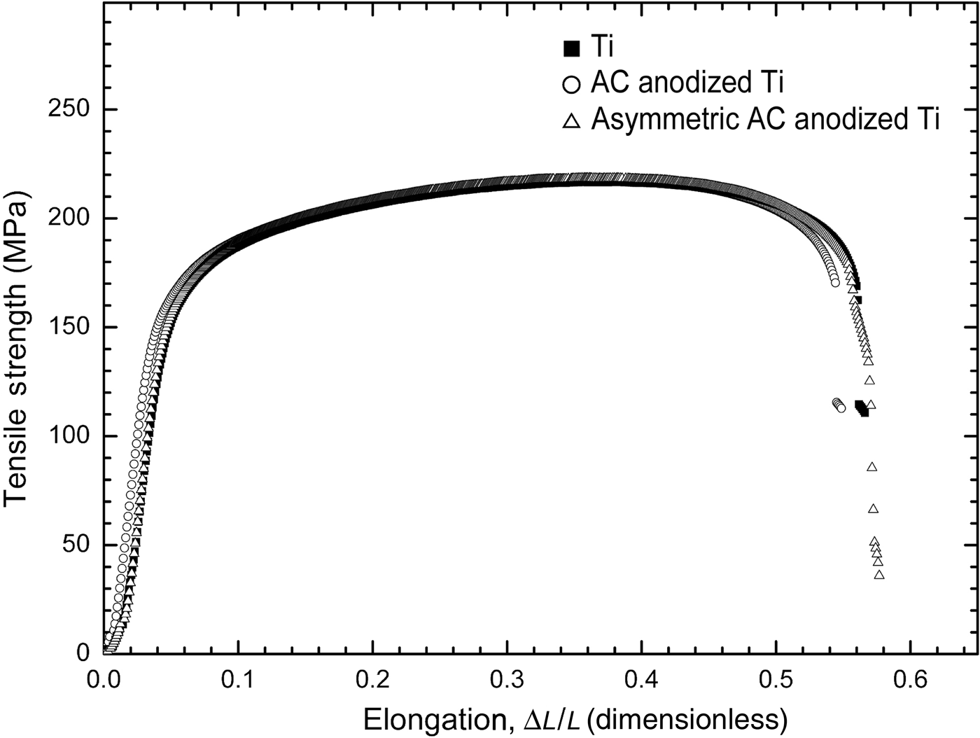
It is well known that absorbed hydrogen in Ti causes hydrogen embrittlement.[Reference Shimogori35, Reference Fukuzuka, Shimogori, Satoh and Tomari36] Tensile tests of Ti substrate were also conducted. These tensile tests are strongly influenced by the surface conditions, including the presence of cracks, scratches, pits, and so on. As shown in Figs. 1(a)–1(d), high V AC caused surface defects. We conducted a tensile test for the untreated Ti, AC anodized Ti at V AC = 40 V, and asymmetric AC anodized Ti at V AC = 40 V and R = 1.0 kΩ. These results are shown in Fig. 5. The results indicated that there are no differences between these specimens in terms of the tensile strength and the elongation. Thus, the absorbed hydrogen does not affect substrate properties. The amount of absorbed hydrogen in Ti substrate might be higher when prepared above V AC = 90 V with the special electrical circuit. However, during the asymmetric AC electrolysis, spark discharge is not observed, indicating that the hydrogen content is not high compared with AC anodized Ti at V AC = 40 V without the special electrical circuit. Because spark discharge caused by hydrogen evolution is not observed on AC anodized Ti, it is not possible for the nanosized porous oxide layer to be degraded by hydrogen embrittlement in this condition.
Results of tensile strength (MPa) versus elongation (ΔL/L) measurements for: (i) untreated Ti (filled squares); (ii) Ti after AC anodization at V AC = 40 V and f AC = 60 Hz (open circles); and (iii) Ti after asymmetric AC anodization at V AC = 40 V, f AC = 60 Hz, and R = 1.0 kΩ (open triangles).

Conclusions
In order to simplify the procedure employed to the formation of bioactive porous oxide layers on Ti surfaces, we studied the application of AC electrolysis for anodizing it. The new and original findings and the main concluding remarks are summarized as follows: (i) nanosized porous layers on Ti cannot be obtained by AC electrolysis in a 1.0 M aqueous H2SO4 solution at 303 K due to spark discharge; (ii) application of a special electric circuit which consists of a variable resistor and two diodes inhibits the HER and leads to the formation of a nanosized porous layer on Ti; (iii) the growth of an apatite layer on a nanosized porous layer on Ti can be achieved by employing asymmetric AC electrolysis; and (iv) the process of asymmetric AC electrolysis does not result in hydrogen embrittlement of a Ti. As a consequence of our findings, the possibility of forming nanosized porous oxide layers on the surfaces of Ti has been demonstrated using the AC electrolysis in a short period of time and without spark discharge. Therefore, it is expected that this surface treatment method will be efficiently used for bioactivation of Ti and its alloys.
Acknowledgments
The authors thank to Daniel Morrall (Kyoto University) for his valuable comments on this manuscript. This work was supported by JSPS KAKENHI Grant Number JP24550241. A part of this work was financed by the Light Metal Educational Foundation, Inc., Japan. In addition, this work was partially funded by the Natural Sciences and Engineering Research Council of Canada.