I. INTRODUCTION
Thermochemical boriding of iron alloys has been applied to fabricate good wear- and corrosion-resistant materials as an effective surface treatment method. Reference Dybkov, Lengauer and Barmak1,Reference Hu, Fan, Wu, Yan and Chen2 In the boriding process, iron borides with both monophase Fe2B and FeB-based polyphase coatings can be obtained by diffusing boron atoms into the surface of metallic materials and then used mainly to improve the surface hardness and wear resistance of the components for tribological applications. Reference Ozdemir, Usta, Bindal and Ucisik3–Reference Kayali, Taktak, Ulu and Yalcin6 Besides, the boriding layers or boride-containing iron alloys show good corrosion resistance to liquid zinc owing to their nonwetting with liquid zinc and therefore can be utilized for planting in the surface of the components as a wear-resistant or corrosion-resistant working layer for corrosion equipment of continuous galvanizing lines or aluminum–zinc die casting mold. Reference Tsipas, Triantafyllidis, Kiplagat and Psillaki7–Reference Tsipas and Rus11
Recently, much attention has been paid to boride-based coatings or Fe2B-containing iron alloys because of their good corrosion resistance in a molten zinc bath. Reference Tsipas, Triantafyllidis, Kiplagat and Psillaki7–Reference Ma, Xing, Yi, Fu, Zhang, Li, Zhang, Liu and Zhu9 Fe2B intermetallic possessing good thermal stabilization, wear, and corrosion resistance is always introduced into materials as an important skeleton constitution to resist corrosion or wear, and it can be used as a working layer imbedded into the surface of components for applications (i.e., the wear- and corrosion-resistant working layer). Reference Ma, Xing, Yi, Fu, Zhang, Li, Zhang, Liu and Zhu10,Reference Tsipas and Rus11 According to the studies, Reference Tsipas, Triantafyllidis, Kiplagat and Psillaki7–Reference Tsipas and Rus11 it can be revealed that Fe2B intermetallic has an improved corrosion resistance in molten zinc. The interaction or synergetic effect between Fe2B corrosion-resistant skeleton and ductile iron matrix of Fe–B alloy resisting liquid zinc has been systematically investigated. Reference Ma, Xing, Yi, Fu, Zhang, Li, Zhang, Liu and Zhu9,Reference Ma, Xing, Yi, Fu, Zhang, Li, Zhang, Liu and Zhu10
In addition, some investigations have revealed the effects of boride or carbide anisotropy on wear and corrosion resistance, while others reveal no significant effect of carbide anisotropy on wear resistance using a three-body abrasion test under low-stress conditions. Reference Yi, Xing, Ma, Fu, Li, Chen, Yan, Zhang and Zhang12–Reference Wang, Song, Qiao and Wang16 Moreover, Ti-containing borides display anisotropy on thermal expansion coefficient (TEC) and elastic moduli along different grain orientations. Reference Sun, Gao, Xiao, Li and Wang17 Yin et al. reveal that Fe2B can transform into a FeB phase in the Zn–Fe–B system when corroded in liquid zinc. Reference Yin, Ruan, Zhao, Liu and Li18 Besides, in previous research, the preparation of bulk Fe2B crystal by using mechanical ball milling and plasma activated sintering was studied, and the fracture toughness of sintered Fe2B was also measured. Reference Huang, Ma, Xing and Wang19
Nevertheless, there is little research on the influence of Fe2B-grain orientation on its microstructure and properties. In this study, we investigate the microstructure and properties of as-cast bulk Fe2B intermetallic with various grain orientations, and the effects of Fe2B-grain orientation on anisotropy of its properties have also been discussed to understand the microstructural and behavioral variations of iron boride. Accordingly, the dependent microstructure–property relationship of bulk Fe2B intermetallic has been discussed.
II. EXPERIMENTAL PROCEDURES
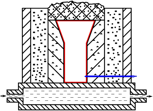
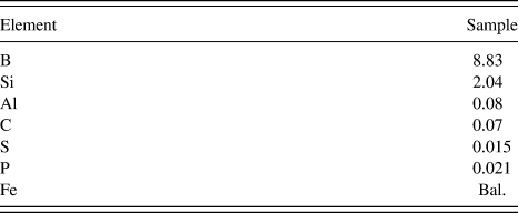
According to Fe/B ratio (2:1) in the Fe2B molecular formula, bulk Fe2B intermetallic in the present work was fabricated in a ZG-5-type vacuum medium frequency induction melting furnace with a vacuum degree of 1 Pa. The initial materials were clean pure iron and Fe–19.55 wt% B ferroalloy. Figure 1 shows a schematic diagram of the directional solidification device with a longitudinal thermal gradient to obtain unidirectional solidified microstructure of Fe2B intermetallic. The device of directional solidification consists of a copper permanent mold cooled with circulating water and a wrapper of sodium silicate-CO2 bonded sand with exothermal materials. The oriented and nonoriented Fe2B intermetallics were melted at 1480–1520 °C and then poured into a sand mold at 1430 °C, respectively, to solidify the desired microstructures. Randomly oriented grains of small size next to the wall of permanent mold (i.e., equiaxed grain zone) were removed 3 mm, and only large columnar grains were used as the oriented alloys. The chemical composition of Fe2B intermetallic is listed in Table I.
Schematic device of directional solidified bulk Fe2B intermetallic (solidification rate of about 17 °C measured by a thermocouple).

Chemical composition of Fe2B analyzed via a spark emission spectrometer (wt%).

Thermal expansion properties of bulk Fe2B intermetallic were measured using a PCY-II type thermal dilatometer. The dimensions of Fe2B intermetallic for linear expansion measurement are 50 mm in length and 5 mm in diameter. The heating rate of the tested specimens was 5 °C min−1, and the testing temperature ranged from 350 to 600 °C.
Microhardness of Fe2B intermetallic was determined by means of an HXD-type 1000 TMC/LCD Vikers-hardness tester with a load of 300 gf. Rectangular bars for fracture toughness test of Fe2B intermetallic were cut using an electro-discharge machine. Single edge notched bend specimens with V-notch precrack of a/W ratio about 0.5 were ground and polished to the final dimensions of 3 mm × 5 mm × 20 mm. Then, the fracture toughness was measured by using a three-point bending test (INSTRON-1195) with a cross-head speed of 0.5 mm min−1. The fracture toughness K IC can be characterized by using Eqs. (1) and (2) following the ASTM E399 test standard. Reference Huang, Ma, Xing and Wang19,Reference Liu, Jiang, Cao, Mei, Wu, Zhang, Xiao, Wang and Ding20
 $${K_{{\rm{IC}}}} = Y{{3PL} \over {2b{W^2}}}{a^{1/2}}\quad ,$$
 $$Y = 1.93 - 3.07{a \over W} + 14.53{\left( {{a \over W}} \right)^2} - 25.11{\left( {{a \over W}} \right)^3} + 25.80{\left( {{a \over W}} \right)^4}\quad ,$$
where Y is the geometrical factor related to the crack depth ratio, P is the maximum load, b is the width of the bar, L is the length of the bar, W is the thickness of the bar, and a is the initial crack length.
Corrosion test of Fe2B intermetallic in liquid zinc was carried out at the temperature of 460 °C. The size of tested samples ground by 2000 mesh carborundum paper was 75 mm × 10 mm × 4 mm, dipped into liquid zinc for 40 mm in depth. The volume of liquid zinc for corrosion test was 2.5 × 10⁻³ m3 (melting about 17 kg pure zinc), and the immersion corrosion test was carried out under the static condition. Corrosion depth was obtained using a thickness-loss method followed by investigations. Reference Ma, Xing, Yi, Fu, Zhang, Li, Zhang, Liu and Zhu10,Reference Wang, Lin, Wang and Chen21,Reference Ma, Xing, Fu, He, Bai, Li and Bai22 Then, the corrosion rate is characterized as follows (Eq. (3)) (Refs. Reference Ma, Xing, Fu, Yi, Zhi and Li8–Reference Ma, Xing, Yi, Fu, Zhang, Li, Zhang, Liu and Zhu10, Reference Wang, Lin, Wang and Chen21, and Reference Ma, Xing, Fu, He, Bai, Li and Bai22):
 $$R = {{a - b} \over {2t}}\quad ,$$
where R is the corrosion rate (mm·h−1), a is the original thickness (mm), b is the final thickness (mm), and t is the corrosion time (h). The factor of 1/2 in the equation is used to reflect the fact that the average thickness change of the sample is caused by the corrosion of both faces of the sample.
The microanalysis on samples was carried out by using an optical microscope (OM), a scanning electron microscope with backscattered electron image (BEI), x-ray diffraction (XRD), electron probe microanalysis (EPMA) equipped with energy dispersive x-ray and wave length dispersive x-ray (WDX) analysis to identify microstructures. For metallographic observations, all samples were etched in a 4 vol% nital solution. XRD was performed on a MXP21VAHF diffractometer with copper Kα radiation as an x-ray source using continuous scanning at 40 kV and 200 mA. The corroded sample was scanned in 2θ ranging from 20° to 60° with a scanning speed of 2°·min−1 and a step space of 0.02°.
III. RESULTS AND DISCUSSION
A. Effect of orientation on microstructure
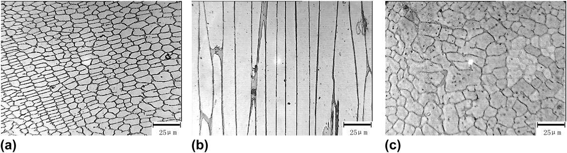
Figure 2 shows an optical microstructure of the as-cast bulk Fe2B intermetallic. From Fig. 2(a), it can be observed that the transverse section of unidirectional solidified Fe2B intermetallic shows rectangle-shaped grains with the mean size of 14.1 μm in length and 5.8 μm in width, while the longitudinal section shows columnar grains with the growth direction opposite to the heat-squeeze direction [Fig. 2(b)]. However, the ordinary microstructure of nonoriented Fe2B intermetallic by a casting method is random oriented grains (i.e., equiaxed grains) and the grain size is somewhat heterogeneous [Fig. 2(c)]. Moreover, a little Si-containing compound is found at the grain boundary among Fe2B grains, which is formed owing to the presence of about 2 wt% Si element in the raw materials of ferroboron. Reference Raghavan23–Reference Li and Chang25
Optical microstructure of the as-cast bulk Fe2B intermetallic: (a) Transverse section; (b) longitudinal section; and (c) nonoriented section.

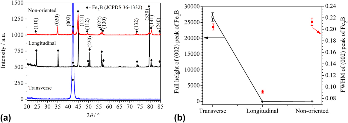
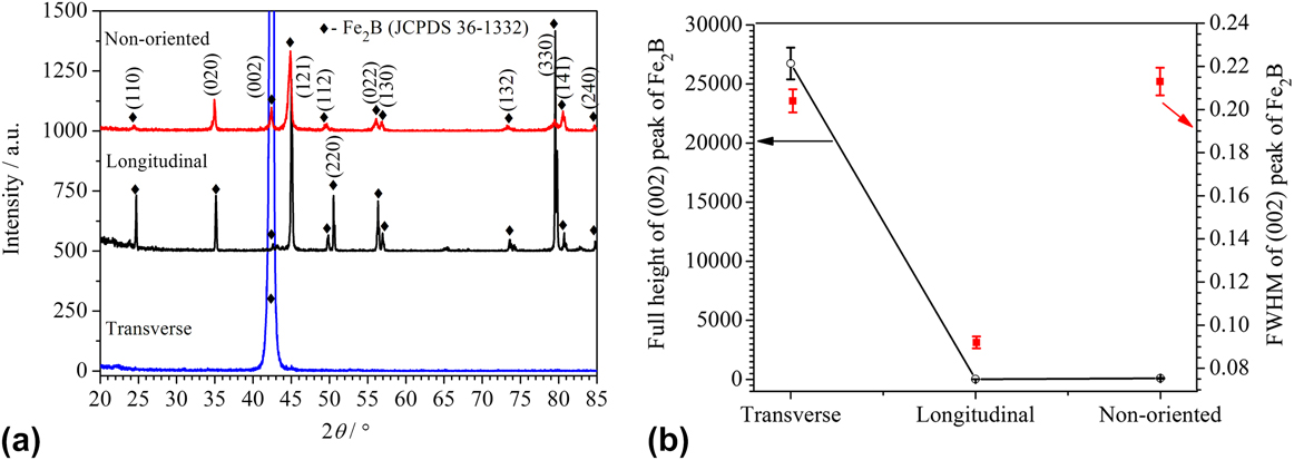
Figure 3 shows XRD analysis of Fe2B intermetallic. It can be seen that a remarkably strong peak of the (002) plane is detected from Fe2B crystal in the transverse section (JCPDS 36-1332). Nevertheless, the (002) peak in a longitudinal section is evidently disappeared and the (002) peak of nonoriented Fe2B also becomes very weak [Fig. 3(a)]. It indicates that unidirectional solidified Fe2B intermetallic shows obviously textured structure and its preferred growth direction is [002] orientation owing to orthorhombic structure of Fe2B. Reference Tsipas, Triantafyllidis, Kiplagat and Psillaki7–Reference Ma, Xing, Yi, Fu, Zhang, Li, Zhang, Liu and Zhu10 Figure 3(b) shows the full height and full width at half maximum (FWHM) of (002) peaks of Fe2B from XRD results in Fig. 3(a). It further suggests that strong Fe2B textured grains can form along their longitudinal axis and the [002] orientation is the preferred growth direction owing to the opposite heating squeezed direction (i.e., orthorhombic structure of Fe2B with a = b = 0.5109 nm and c = 0.4249 nm determined by experimental d space from XRD data).
XRD analysis of bulk Fe2B intermetallic: (a) XRD pattern and (b) full height and FWHM of (002) peaks for Fe2B.
A little Si-rich compound formed at grain boundaries is detected by WDX analysis listed in Table II. According to the Fe–Si–B ternary phase diagram and other studies, Reference Raghavan23,Reference Aronsson and Engström24 the Si-rich compound is determined to be Fe5SiB2 phase, which contains 8.53 wt% Si discovered in many investigations. Reference Raghavan23–Reference Li and Chang25
Electron microprobe analysis of borides in bulk Fe2B intermetallic.

%B is given by difference. The values are based on an average of 10 different areas per sample.
B. Effect of orientation on thermal expansion property
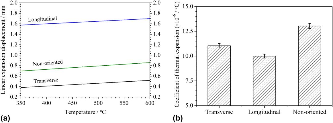
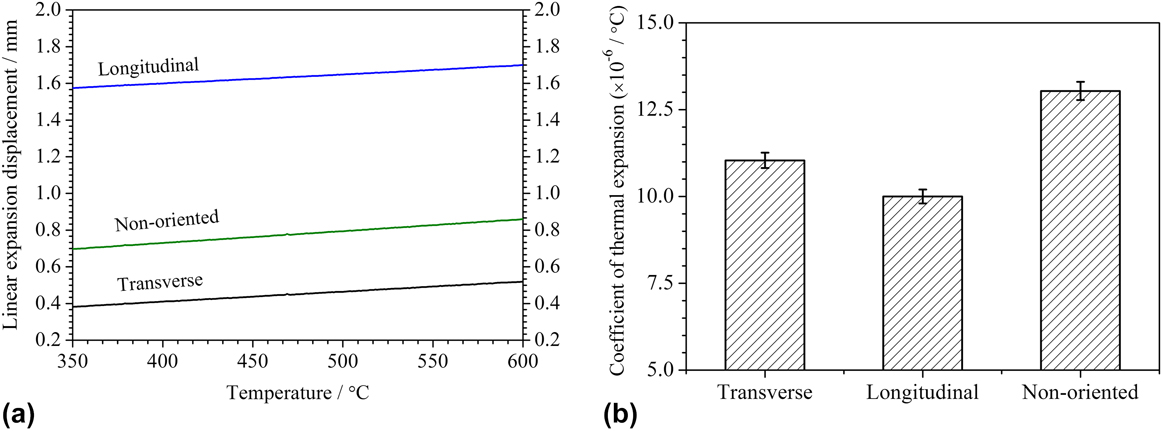
Figure 4 displays the thermal expansion property of Fe2B intermetallic. It can be seen that although the linear expansion displacement of a longitudinal sample is much larger than that of transverse and nonoriented samples as the temperatures range from 350 to 600 °C [as shown in Fig. 4(a)], the slope of linear expansion displacement of nonoriented Fe2B intermetallic is much higher than that of oriented Fe2B intermetallic (i.e., transverse and longitudinal samples). According to TEC shown in Fig. 4(b), the TEC values of bulk Fe2B intermetallic are 11.04 × 10⁻⁶, 10.00 × 10⁻⁶, and 13.04 × 10⁻⁶ °C−1 for transverse, longitudinal, and nonoriented Fe2B grains, respectively. It reveals that the thermal expansion property of Fe2B intermetallic can be strongly affected by Fe2B grain orientation which may be related to the atomic spatial distribution of Fe2B crystal. Reference Sun, Gao, Xiao, Li and Wang17,Reference Li, Fu, Xu, Zhang and Yu26
Thermal expansion property of Fe2B intermetallic with various grain orientations: (a) Linear expansion displacement and (b) TEC.
According to the crystal structure of Fe2B with a space group of I 4/mcm (No. 140) and bbc tetragonal structure (C16, CuAl2-type), eight Fe atoms are in general position (8h site along z-axis by 0.25c and 0.75c and also along x- and y-directions by 0.5a and 0.5b in Fe2B cell), while four B atoms are in special position (4a site). Reference Sun, Gao, Xiao, Li and Wang17,Reference Xiao, Xing, Ding and Su27 Therefore, the atomic density of boron along the c-direction (i.e., [002] direction) is higher than that of Fe atom, and it leads to the smaller atomic thermal motion and thermal expansion property along the longitudinal direction compared with other orientations (i.e., transverse and nonoriented samples) owing to more B–B covalent bond. Reference Sun, Gao, Xiao, Li and Wang17 On the other hand, the thermal expansion property may be affected by lattice dynamical properties and thermal–physical properties of Fe2B cell volume along various orientations caused by phonon dispersion. Sun reveals that Ti-borides possess different CETs along [100], [010], and [001] orientations owing to anharmonic effect of the thermal energy of lattice vibration, which brings about volumetric coefficient variation. Reference Sun, Gao, Xiao, Li and Wang17,Reference Van de Walle and Ceder28 That is to say, the anharmonic effect of lattice vibration for Fe2B intermetallic with various grain orientations may probably result in the differences of thermal expansion property along different Fe2B orientations as shown in Fig. 4. In addition, the anharmonic effect of lattice vibration may be significantly influenced by various defects in Fe2B intermetallic with various crystal orientations such as vacancies and site disorder. Reference Sun, Gao, Xiao, Li and Wang17,Reference Quong and Liu29 Therefore, Fe2B intermetallic along [002] orientation can generate a small thermal energy of lattice vibration compared to other crystal orientations in oriented Fe2B intermetallic, while nonoriented grains of Fe2B intermetallic may achieve more lattice dynamical properties according to the special structure and distribution of random Fe2B cell.
C. Effect of orientation on microhardness and fraction toughness
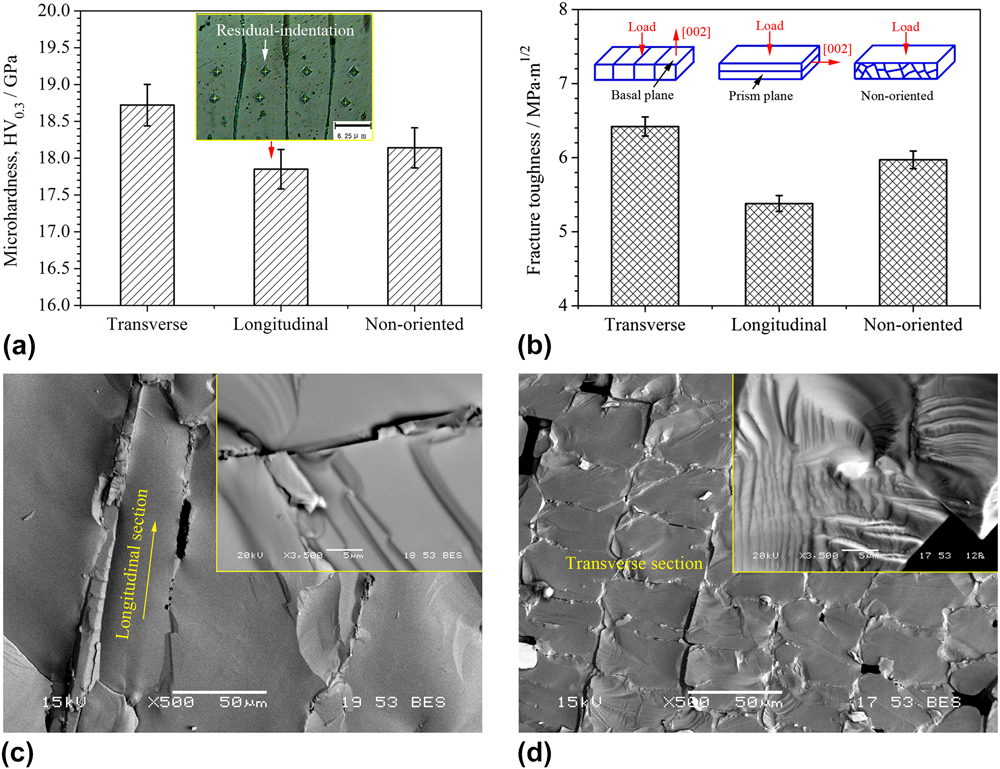
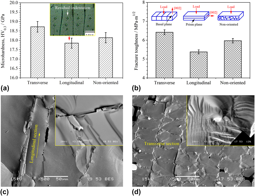
Figure 5 shows the microhardness and fracture toughness of bulk Fe2B intermetallic. From Fig. 5(a), it is clear that transverse Fe2B intermetallic possesses the highest Vickers hardness value (∼18.72 GPa) compared with longitudinal and nonoriented Fe2B intermetallics (∼17.85 and ∼18.14 GPa, respectively), which is related to atom bounding energy of different crystal planes of Fe2B lattice. Reference Li, Fu, Xu, Zhang and Yu26,Reference Xiao, Xing, Ding and Su27 From Fig. 5(b), the fracture toughness of the as-cast Fe2B intermetallic ranges from 5.97 to 6.42 MPa·m1/2 when loaded along various Fe2B orientations (i.e., transverse, longitudinal, and nonoriented sections, respectively), which is higher than that of sintered bulk Fe2B owing to the presence of a few pores among them. Moreover, the fracture toughness of transverse Fe2B intermetallic is larger than that of longitudinal and nonoriented Fe2B, which is attributed to the inherent brittleness vertical to the [002] orientation of Fe2B. Reference Li, Fu, Xu, Zhang and Yu26,Reference Xiao, Xing, Ding and Su27 Thus, more microcracks may be produced vertical to the [002] orientation under a deformation process. Reference Li, Fu, Xu, Zhang and Yu26,Reference Hernández-Sanchez, Rodriguez, Meneses-Amador, Bravo-Bárcenas, Arzate-Vazquez, Martínez-Gutiérrez, Romero-Romo and Campos-Silva30 Many investigations were carried out to investigate the large inherent brittleness perpendicular to the [002] orientation and sensibility of microcracking because of the weaker B–B covalent bond and bounding energy as well as the interaction of iron and boron atoms, which also results from the spatial heterogeneous distribution of Fe and B atoms in Fe2B lattice. Reference Li, Fu, Xu, Zhang and Yu26,Reference Xiao, Xing, Ding and Su27,Reference Guo31,Reference Ma, Xing, Liu, Yi, Fu, Zhang and Li32 Therefore, bulk Fe2B intermetallic with various orientations displays strongly anisotropy. Besides, the configurations or hybridizations of atomic orbitals depending on energy differences and symmetric properties of Fe and B in Fe2B cell may remarkably affect the mechanical properties related to its chemical structure, such as bulk modulus and fracture toughness. Reference Sun, Gao, Xiao, Li and Wang17,Reference Xiao, Xing, Ding and Su27–Reference Quong and Liu29 From Figs. 5(c) and 5(d), there are more tearing and local slipping characteristics on the (002) plane when loaded vertically. Due to the strong bounding energy and small microcracking of Fe2B intermetallic on the (002) plane, the microhardness and fracture toughness are largest along the [002] orientation. Reference Li, Fu, Xu, Zhang and Yu26,Reference Xiao, Xing, Ding and Su27 Hence, the differences among various orientations for Fe2B intermetallic depend on not only lattice structures but also microcracking sensibility of Fe2B.
Microhardness and fracture toughness of bulk Fe2B intermetallic: (a) Vickers hardness; (b) fracture toughness; (c) transverse fracture; and (d) longitudinal fracture.
D. Effect of orientation on corrosion resistance to liquid zinc
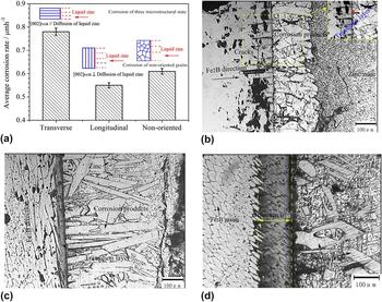
Figure 6 shows corrosion resistance and OM interfacial morphologies of bulk Fe2B intermetallic with various grain orientations against liquid zinc. From Fig. 6(a), it is obviously found that longitudinal Fe2B perpendicular to the diffusion direction of liquid zinc has the best corrosion resistance to liquid zinc owing to its beneficial barrier effect and thus strongly restricts the liquid zinc diffusion path compared with the rest orientation samples. On the other hand, the failure of bulk Fe2B intermetallics with different grain orientations can lead to various corrosion interfaces and corrosion process as well as the occurrence of microcracks around the corrosion interface. Reference Ma, Xing, Fu, Yi, Zhi and Li8,Reference Ma, Xing, Yi, Fu, Zhang, Li, Zhang, Liu and Zhu10 According to interfacial morphologies from Figs. 6(b)–6(d), it is clear that there exists a transition layer close to the inner Fe2B substrate except for Fe–Zn compounds (mainly ζ-FeZn13). Reference Ma, Xing, Fu, Yi, Zhi and Li8,Reference Ma, Xing, Yi, Fu, Zhang, Li, Zhang, Liu and Zhu10,Reference Wang, Lin, Wang and Chen21 The transition layer in a transverse sample displays an interlocking shape overlain at the interface with a mean width of ∼30 μm, while it is lath-shaped in the longitudinal sample with an interface of ∼20 μm thickness, which is approximate to the grain width of longitudinal Fe2B. Meanwhile, an obvious intergranular corrosion along the grain boundary is observed for nonoriented sample with a corrosion thickness of ∼30 μm. Therefore, the grain orientation of Fe2B intermetallic can markedly create different interfacial morphologies and result in various corrosion resistances in liquid zinc, which is mainly attributed to various zinc diffusion paths and zinc concentrations following the above corrosion manners.
Corrosion rate and OM interfacial morphologies of bulk Fe2B intermetallic in liquid zinc under static condition: (a) Corrosion rate; (b) OM interfacial morphologies of transverse section; (c) OM interfacial morphologies of longitudinal section; and (d) OM interfacial morphologies of nonoriented section.

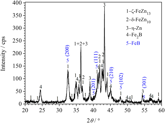
Figure 7 shows the XRD result of bulk Fe2B intermetallic corroded in liquid zinc. It is found that some FeB phases indexed by JCPDS 32-0463 and/or 65-2599 can be accurately detected except for ζ-FeZn13 (JCPDS 65-1238), δ-FeZn10 (JCPDS 65-1238), and the residual Fe2B (JCPDS 36-1332) in corrosion layers, which is well agreed with other investigations. Reference Ma, Xing, Fu, Yi, Zhi and Li8,Reference Ma, Xing, Yi, Fu, Zhang, Li, Zhang, Liu and Zhu10,Reference Yin, Ruan, Zhao, Liu and Li18,Reference Wang, Lin, Wang and Chen21
XRD result of corrosion layer for Fe2B intermetallic corroded in liquid zinc.
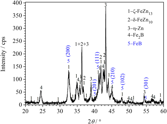
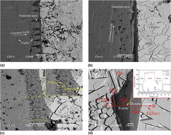
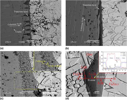
Figure 8 shows BEI morphologies and EPMA line analysis of corrosion layers. It reveals that zinc corrosion can mainly proceed along columnar grain boundaries of transverse Fe2B intermetallic as shown in Fig. 8(a), and some cracks generate through the width direction of bulk Fe2B grains accompanying slight dissolution of Fe2B and formation of transition layer FeB phase detected by XRD. Reference Ma, Xing, Fu, Yi, Zhi and Li8,Reference Ma, Xing, Yi, Fu, Zhang, Li, Zhang, Liu and Zhu10,Reference Yin, Ruan, Zhao, Liu and Li18,Reference Wang, Lin, Wang and Chen33 However, a layer-by-layer corrosion vertical to the longitudinal section of Fe2B occurs and the gray transition layer also forms as shown in Fig. 8(b). Clearly, some ζ-FeZn13 is found near the surface of corrosion layers. It indicates that the corrosion of Fe2B in liquid zinc may result in the strong release of free Fe atom to form gray transition layer FeB phase under high zinc chemical potential according to lattice reorganization. Reference Yin, Ruan, Zhao, Liu and Li18,Reference Ma, Xing, Fu, He, Bai, Li and Bai22 Simultaneously, partial released Fe can combine with Zn atom to form ζ-FeZn13 phase as reported by other studies. Reference Yin, Ruan, Zhao, Liu and Li18,Reference Ma, Xing, Fu, He, Bai, Li and Bai22,Reference Marder34 From the corrosion of nonoriented Fe2B grains in Fig. 8(c), it is clear that many Fe2B grains are corroded by liquid zinc, and grain-boundary corrosion is intensively dominant in liquid zinc. The corroded Fe2B in corrosion layers and the corresponding EPMA analysis along line segment AB on spalling Fe2B surrounded by liquid zinc in Fig. 8(d) reveal that the peripheral gray transition layer of corroded Fe2B possesses a uniform Fe content, and there is a sharp linear decrease of Fe at the Fe2B/transition layer interface [I-zone/II-zone interface and II-zone/III-zone interface shown in Fig. 8(d)]. It further suggests that the uniform FeB compound in a transition layer can naturally form. Reference Yin, Ruan, Zhao, Liu and Li18,Reference Ma, Xing, Fu, He, Bai, Li and Bai22 From the analysis above, the crucial corrosion process of all bulk Fe2B with various orientations in liquid zinc includes slight dissolution and main phase transition process from Fe2B to FeB intermetallic, which governs the corrosion of bulk Fe2B in liquid zinc.
BEI morphologies and EPMA line analysis of bulk Fe2B intermetallic in liquid zinc: (a) Transverse section; (b) longitudinal section; (c) nonoriented section; and (d) spalling Fe2B surrounded by liquid zinc and corresponding EPMA analysis along line segment AB in corrosion layers.

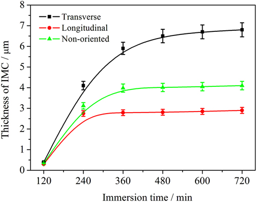
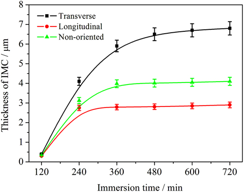
Figure 9 shows the growth thickness of FeB intermetallic compound (IMC) transformed from Fe2B intermetallic in liquid zinc corrosion. It can be seen that the growth thickness of all Fe2B with various orientations conforms to the law of approximately parabolic increase. Reference Dybkov and Duchenko35 Besides, the longitudinal Fe2B perpendicular to diffusion direction of liquid zinc (i.e., liquid zinc corrosion direction) has the slowest growth thickness compared to samples with other Fe2B orientations, which is ascribed to a small corrosion path and beneficial barrier effect of Fe2B generated by grain orientations.
Growth thickness of FeB IMC transformed from Fe2B intermetallic during liquid zinc corrosion.
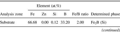
According to the Zn–Fe–B system reported by Yin, Reference Yin, Ruan, Zhao, Liu and Li18 a coexisting phase of FeB, ζ-FeZn13, and η-Zn can be established. WDX results listed in Table III also reveal that the gray transition layer is FeB phase and it is supersaturated with zinc atom, which is well agreed with XRD result and other investigations. Reference Yin, Ruan, Zhao, Liu and Li18,Reference Ma, Xing, Fu, He, Bai, Li and Bai22 Based on the microstructural analysis and observations on interfaces, it can be confirmed that zinc corrosion of bulk Fe2B intermetallic remarkably not only depends on grain orientation of Fe2B but also is affected by dissolution and FeB phase transition produced from zinc potential or concentration.
Average composition of substrate (bulk Fe2B intermetallic) and corrosion layers (transition layer and Fe–Zn layer) measured via WDX analysis at 20 different areas.

%B is given by difference. The values are based on an average of 20 different areas per samples.
IV. CONCLUSIONS
This study investigates the effects of crystal orientation on microstructure and properties of bulk as-cast Fe2B intermetallic. The results obtained are as follows.
-
(1) The unidirectional solidified Fe2B intermetallic possesses a strong (002) texture in the transverse direction with a mean grain size of 14.1 μm in length and 5.8 μm in width while random Fe2B grains produce under ordinary solidification conditions.
-
(2) The nonoriented Fe2B intermetallic has the highest linear expansion coefficient of 13.04 × 10⁻⁶ °C−1 while the microhardness and fracture toughness of transverse Fe2B intermetallic are larger than that with other grain orientations and their values are ∼18.72 GPa and 6.42 MPa·m1/2, respectively.
-
(3) Liquid zinc corrosion results indicate that unidirectional Fe2B intermetallic with Fe2B long axis perpendicular to the direction of liquid zinc corrosion displays the best corrosion resistance to liquid zinc owing to its beneficial barrier effect. The transition phase FeB can naturally form and parabolically grow during liquid zinc corrosion.
ACKNOWLEDGMENTS
The authors thank the financial support for this work from the Natural Science Foundation of China under Grant Nos. 51271142, 51301128, & 51274016, the Specialized Research Fund for the Doctoral Program of Higher Education of China under Grant Nos. 20110201130008 & 20120201120005, the National Science Foundation for Post-doctoral Scientists of China under Grant Nos. 2012M521767 & 2013T60875, the Natural Science Foundation of Shaanxi Province under Grant No. 2014JQ7281, the Shaanxi provincial post-doctoral research project, and the Fundamental Research Funds of Xi'an Jiaotong University under Grant Nos. xjj2013038 & xjj2014167.