Introduction
Spinal cord injuries (SCIs) continue to be among the most debilitating injuries because of the lack of regeneration capabilities of damaged neural tissue [Reference Ahuja, Jefferson, Nori, Kotter, Druschel, Curt and Fehlings1]. The development of a glial scar at the site of injury provides a barrier to the repair, regeneration, and reconnection of severed axons. Previous research has focused on the creation of an implantable fiber scaffold that would act as a bridge across the glial scar and provide guidance for axonal outgrowth [Reference Ingavle and Leach2]. Recently, coaxial core/sheath fiber structures have shown promise as a more advanced scaffold material [Reference Raspa, Marchini, Pugliese, Mauri, Maleki, Vasita and Gelain3]. These core/sheath fiber structures allow for delivery of external stimuli in the form of biochemical or electrical cues, in addition to topographical guidance provided by the fiber surface. In this article, we explore the use of electrospun core/sheath fibers with a conductive conjugated polymer core, insulated by a nonconductive polymer sheath. This is the first study to report a successful method for generating conductive-core/insulating-sheath fibers by coaxial electrospinning and evaluation of these fibers in vitro to aid in neuronal outgrowth and extension of chick dorsal root ganglia (DRG).
The technique of electrospinning to produce fiber scaffolds for axonal regeneration has been widely explored [Reference Schaub, Johnson, Cooper and Gilbert4, Reference Hurtado, Cregg, Wang, Wendell, Oudega, Gilbert and McDonald5, Reference Corey, Lin, Mycek, Chen, Samuel, Feldman and Martin6, Reference Wang, Mullins, Cregg, Hurtado, Oudega, Trombley and Gilbert7]. Polymer fiber scaffolds developed using poly-L-lactic acid (PLLA) [Reference Hurtado, Cregg, Wang, Wendell, Oudega, Gilbert and McDonald5, Reference Corey, Lin, Mycek, Chen, Samuel, Feldman and Martin6, Reference Wang, Mullins, Cregg, Hurtado, Oudega, Trombley and Gilbert7, Reference He, Tang, Prabhakaran, Liao, Tian, Zhang, Xue and Ramakrishna8, Reference Zhang, Zheng, Liang and Gao9, Reference Koppes, Zaccor, Rivet, Williams, Piselli, Gilbert and Thompson10], poly-caprolactone (PCL) [Reference Mohtaram, Ko, Agbay, Rattray, Neill, Rajwani, Vasandani, Thu, Jun and Willerth11, Reference Xie, Liu, MacEwan, Bridgman and Younan12, Reference Huang, Ouyang, Niu, He, Ke, Jin, Li, Fang, Liu, Fan and Lin13, Reference Xu, Miszuk, Zhao, Sun and Fong14, Reference Entekhabi, Haghbin Nazarpak, Moztarzadeh and Sadeghi15, Reference Jenkins, Laughter, Lee, Lee, Freed and Park16], poly(lactide-co-glycolide) (PLG) [Reference Pawar, Cummings, Thomas, Shea, Levine, Pfaff and Anderson17, Reference Nune, Krishnan and Sethuraman18], poly(L-lactic acid)-co-caprolactone (PLL-CL) [Reference Kijenska, Prabhakaran, Swieszkowski, Kurzydlowski and Ramakrishna19, Reference Bhutto, Zhang, Sun, El-Hamshary, Al-Deyab and Mo20], and silk fibroin [Reference Zhang, Huang, Huang, Liu, Shao, Hu and Song21] have shown potential in aiding axonal outgrowth in vitro. Unfortunately, in vivo studies have not shown the same promise as in vitro studies. An injury model performed in vivo in rats with severed spinal cords treated using implanted scaffolds made of aligned PLLA fibers showed extensive regrowth of the transected spinal cord but did not show significant restoration of hind limb motor function [Reference Hurtado, Cregg, Wang, Wendell, Oudega, Gilbert and McDonald5, Reference Wang, Mullins, Cregg, Hurtado, Oudega, Trombley and Gilbert7, Reference Hurtado, Gilbert, Wang, Cregg, Mullins and Oudega22].
Specifically, investigators have studied ways of enhancing electrospun fiber scaffolds to improve their efficacy in vivo and improve the restoration of motor function. Spinning composite scaffolds with biopolymers such as collagen [Reference Kijenska, Prabhakaran, Swieszkowski, Kurzydlowski and Ramakrishna19], laminin [Reference He, Tang, Prabhakaran, Liao, Tian, Zhang, Xue and Ramakrishna8], or hyaluronic acid [Reference Entekhabi, Haghbin Nazarpak, Moztarzadeh and Sadeghi15] to improve biocompatibility and cell adhesion have been examined. Zuidema et al. and Kuihua et al. developed fiber scaffolds with nerve growth factor (NGF) imbedded in the fibers to improve axonal outgrowth [Reference Zuidema, Provenza, Caliendo, Dutz and Gilbert23, Reference Kuihua, Chunyang, Cunyi and Xiumei24, Reference Lu, Huang, Yu, Cardenas, Wei, Wujcik and Guo25, Reference Nguyen, Ghosh, Hwang, Chanunpanich and Park26, Reference Wang, Liu, Fan, Mo, Ruan and Li27]. In addition to the use of biochemical agents to provide external stimuli during axonal regeneration during cell studies, electrical stimulation has been used to provide an additional source of stimulation for axonal outgrowth. There are several recent studies on electrospun conductive fibers including PEDOT:PSS blended with poly-vinyl alcohol (PVA) [Reference Anderson, Shelke, Manoukian, Yu, McCullough and Kumbar28], polypyrrole coated fibers [Reference Lee, Bashur, Goldstein and Schmidt29], and aniline tetramer-co-polycaprolactone fibers [Reference Guex, Spicer, Armgarth and Glemi30].
An extension of the concept of using the core material to promote axonal outgrowth would be to incorporate conducting polymers within an insulated sheath to create essentially an “artificial axon”. Previously, electrical stimulation has been shown to aid in axonal outgrowth both in vitro and in vivo [Reference Hurtado, Cregg, Wang, Wendell, Oudega, Gilbert and McDonald5, Reference Wang, Mullins, Cregg, Hurtado, Oudega, Trombley and Gilbert7, Reference Koppes, Zaccor, Rivet, Williams, Piselli, Gilbert and Thompson10, Reference Al-Majed, Neumann, Brushart and Gordon31, Reference Wood and Willits32, Reference Elzinga, Tyreman, Ladak, Savaryn, Olson and Gordon33, Reference Schmidt, Shastri, Vacanti and Langer34, Reference Xu, Kou, Zhang, Han, Yin, Deng, Chen and Jiang35] and has been proven to aid in axonal outgrowth when the stimulation is applied along nonconductive fibers [Reference Koppes, Zaccor, Rivet, Williams, Piselli, Gilbert and Thompson10]. In some cases, electrical stimulation with no topographical guidance cues have been shown to aid in axonal outgrowth, whereas some research has shown that when cells are cultured on random fiber mats and exposed to electrical stimulation, axonal outgrowth can be enhanced [Reference Koppes, Zaccor, Rivet, Williams, Piselli, Gilbert and Thompson10]. By using conductive polymers in the formation of fiber scaffolds, particularly coaxial fibers, it may be possible to provide electrical stimulation to the cells when a potential is applied along the fibers. By creating coaxial fibers with a conductive core and insulating sheath, three goals can be achieved: (i) to isolate the conductive polymer with the insulating effects of the polymer sheath, (ii) to create a type of artificial axon that mimics natural neural tissue, and (iii) to place the conductive polymer within an insulating sheath to protect the axons from being overloaded with current.
One conductive polymer with good biocompatibility is poly(3,4-ethylenedioxythiophene) (PEDOT) [Reference Moreno-Cortez, Alvarado-Castañeda, Garcia-Gutierrez, Garcia-Gomez, Sepulveda-Guzman and Garcia-Gutierrez36, Reference Jin, Wang, Feng, Leach, Wu, Mo and Jiang37, Reference Kiristi, Oksuz, Oksuz and Ulusoy38, Reference Yamato, Ohwa and Wernet39, Reference Asplund, Thaning, Lundberg, Sandberg-Nordqvist, Kostyszyn, Inganas and von Holst40]. PEDOT requires a cationic dopant to be electrically conductive [Reference Yamato, Ohwa and Wernet39]. Poly(styrene sulfonate) (PSS) is often used as a dopant-ion with PEDOT because it has low cell toxicity and improves processability [Reference Asplund, Thaning, Lundberg, Sandberg-Nordqvist, Kostyszyn, Inganas and von Holst40]. To further understand axonal interaction with microfiber materials and to improve functional recovery in vivo, we have demonstrated the formation of coaxial fiber scaffolds with a conductive PEDOT:PSS core and an insulating PLLA sheath.
Microfibers were spun using a modified coaxial electrospinning technique, utilizing a 22G/16G spinneret and a 22G/17G spinneret to create fibers with different diameters. Fibers were imaged using fluorescent optical microscopy and field-emission scanning electron microscopy (FE-SEM). Fiber scaffolds were then characterized for fiber diameter, alignment, and density. The mechanical properties of the fibers were studied using a nanoindenter to obtain hardness and Young’s moduli data, and the fibers were chemical analyzed by FTIR spectroscopy. These fibers were studied for their potential as neural tissue scaffolds in vitro using stage E9 chick DRG neural cells cultured on the aligned fiber mat. DRGs were cultured for 5 and 7 days using both single PLLA fibers and PLLA/PEDOT:PSS coaxial fibers and the results analyzed using optical and fluorescence microscopy.
Materials
PLLA was used as the sheath material in all the tests to be consistent with our previous studies demonstrating the benefits of PLLA microfiber scaffolds in aiding axonal outgrowth [Reference Wang, Mullins, Cregg, Hurtado, Oudega, Trombley and Gilbert7]. PLLA was obtained from NatureWorks LLC® and dissolved in chloroform (Sigma-Aldrich) to the desired concentration. If the sheath material can be successfully electrospun to completely contain the core, materials that have properties not usually conducive to electrospinning (e.g., low viscosity) may be used. Here, oleic acid (Sigma-Aldrich) was used as the solvent for the core solution, and the associated conductive polymer was poly(3,4-ethylenedioxythiophene) (PEDOT). Two sources of PEDOT were used. One source was PEDOT nanoparticles from Sigma-Aldrich that used dodecylbenzene sulfonic acid (DBSA) as the counterion. A second PEDOT material with polystyrene sulfonate (PSS) as the counterion was synthesized by oxidative polymerization of 3,4-ethylenedioxythiophene (EDOT) (Alfa Aesar) with styrene sulfonic acid (Alfa Aesar) and sodium sulfate (Sigma-Aldrich).
Results
Testing of core and sheath materials
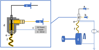
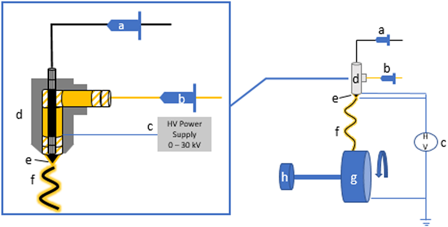
Coaxial electrospinning uses an apparatus and procedures similar to those used for single-strand fibers with a few modifications [Reference Martin, Mullins, Zhao and Qian41]. Details of the original experimental parameters can be found in Martin et al. [Reference Martin, Mullins, Zhao and Qian41] Several nozzle designs were fabricated and tested for electrospinning fibers with a core/sheath structure [Reference Lim42]. In all the designs, the two spinning solutions were placed in separate syringe pumps set at the desired flow rate. The solutions converged at the nozzle to create fibers with a core/sheath structure. Both the inner and outer solutions must be in contact with the power supply and charged at the same voltage. The coaxial nozzle designs have a separate side port for the outer solution, and the core solution is added directly through a syringe needle in the center (Fig. 1).
Schematic.
Several core solutions were tested for their compatibility with electrospinning conductive core/PLLA sheath microfibers. Numerous spinning tests were performed with PVA in distilled water/ethanol in the core, but well-defined core/sheath fibers were not achieved. The water content of this mixture made the solution conductive, causing voltage leaks that created instability in the applied voltage. This disrupted the spinning of continuous, uniform fibers. Similarly, conductive polymer/water suspensions were examined, but the high conductivity of nanoparticles in water also adversely affected the spinning process.
Cationic doped polypyrrole (PPY) is a well-studied conductive polymer and has been studied for use in creating conductive electrospun fibers [Reference Cong, Liu and Chen43]. However, PPY does not disperse well in aqueous or organic suspensions, creating clumping of particle along the fibers, and a discontinuous core structure. Using a similar approach with doped poly(3,4-ethylenedioxythiophene) (PEDOT) nanoparticles dispersed in water (Sigma-Aldrich), greater success was achieved. The nanoparticles did not agglomerate, but the aqueous suspension was still quite conductive, disrupting the production of quality core/sheath fibers. To lower the conductivity of the core solution, suspensions of PEDOT nanoparticles in oleic acid were tested. The oleic acid suspensions were stable, had a lower conductivity, reduced voltage leaks, and produced uniform coaxial fibers.
Effect of solution viscosity and flow rate
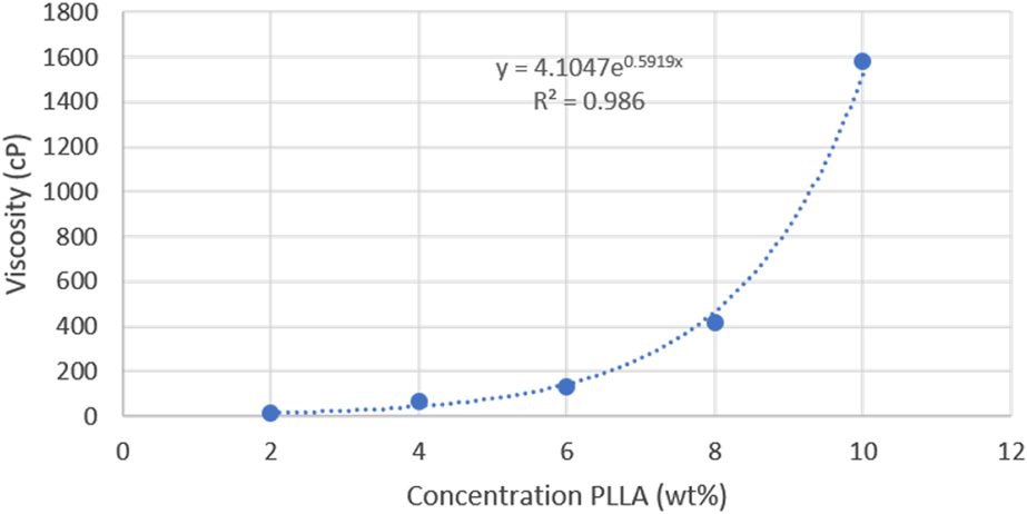
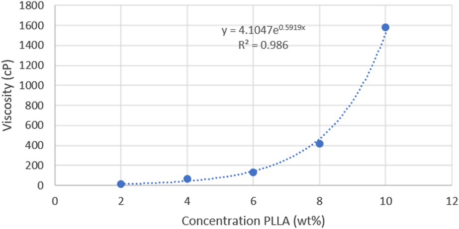
The spinning solution viscosity is a critical variable in successfully electrospinning the sheath material. Solution viscosity increases exponentially with increased concentration yielding a narrow range of suitable viscosity. Viscosity measurements were performed on a range of concentrations for PLLA in chloroform (2 to 10 wt%) and the viscosity profiles were plotted (Fig. 2). Our electrospinning tests showed a PLLA solution concentration between 6 and 8 wt% produced uniform, bead-free fibers, indicating that the ideal range of viscosity for the PLLA sheath solution is between 130 and 420 cP. The viscosity of the core oleic acid–PEDOT solution was around 27 cP; however, the viscosity of the inner solution did not greatly affect the spinning and surface morphology of the coaxial fibers, and all the fibers appeared to be bead-free. The inner solution can be of a lower viscosity because it is encapsulated in the sheath solution in the dual Taylor’s cone, where the viscosity of the sheath solution is most important. Attempts to spin low-viscosity single-stranded oleic acid/PEDOT fibers only resulted in electrospray particles instead of fibers.
Viscosity measurement.
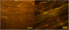
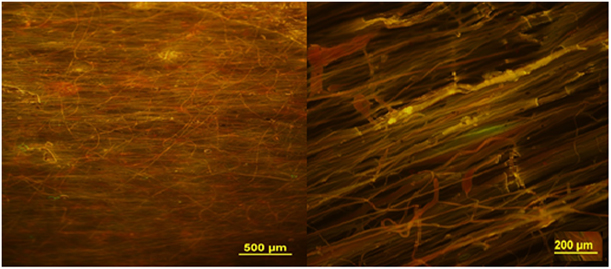
In the successfully electrospun fibers, the outer needle solution was always PLLA in chloroform to create a PLLA sheath [Reference Wang, Mullins, Cregg, Hurtado, Oudega, Trombley and Gilbert7]. Oleic acid was the only successful core solvent found for electrospinning conductive polymer solutions and suspensions. Coaxial electrospinning requires significantly larger flow rates than those for single solutions, with a larger, more elongated Taylor’s cone observed. Within the Taylor’s cone, the inner solution was entirely contained by the outer solution, and the cone encompassed both the inner and outer needles. The flow rates tested were from 0.5 to 1.0 mL/h for the core and 1.0 to 2.0 mL/h for the sheath. The optimal ratio between the outer and inner flow rates was found to be 3:1; therefore, the flow rates used for most of the spinning experiments with the 22G/16G electrospinning needle combination were 1.5 mL/h for the outer solution and 0.5 mL/h for the inner solution. Figure 3 shows the resulting fibers spun at those conditions for both the large and small needle pairs.
Coaxial fibers with different diameters.
Morphology of coaxial fibers
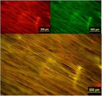
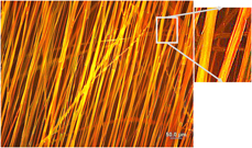
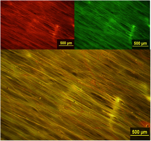
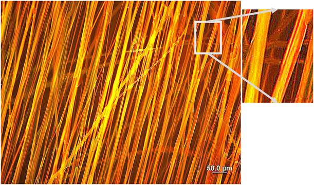
Fluorescence optical microscopy was used to image the fibers and provide evidence that coaxial fibers were achieved through electrospinning. To aid in our fluorescence microscope evaluation, the inner solution was dyed with a green fluorescing dye, coumarin 6, whereas the outer solution was dyed with a red fluorescing dye, rhodamine B. Under fluorescence microscopy, the combination of a green image overlaid with a red image, produces a yellow image where both materials coexist, such as in a core/sheath structure. To determine the success of the coaxial spinning, a red image was first taken of the fibers, then a green image using a Leica BX-15 microscope and X-Cite 120 Fluorescence Illumination System. A digital overlay was created of the two images, producing a yellow image when light passed through both the core and sheath. A yellow center in the fibers is an indication that coaxial fibers were successfully created. Figure 4 shows the red and green fluorescence images, as well as the overlay image for the same region of a PLLA/PEDOT:PSS fiber sample produced with the 22G/17G inner/outer needle combination. Figure 5 shows the digital overlay and detail for a similar sample at a higher magnification and with enhanced image contrast.
Fluorescent microscopic image.
High-contrast fluorescence image of PLLA/PEDOT:PSS coaxial fibers showing a PLLA sheath (red) and encased core (yellow).
The fibers were also analyzed through field-emission scanning electron microscopy (FE-SEM) (Hitachi S4700), and the images analyzed using ImageJ software (NIH). The DiameterJ® plug-in available for ImageJ was used to determine fiber diameter and degree of alignment using the OrientationJ® function by fast Fourier transform (FFT) analysis with the results reported as the angle of deviation from perfect alignment. The diameter of PLLA single-walled fibers, coaxial fibers spun with a 22G/16G inner/outer spinning needle combination, and coaxial fibers spun with a 22G/17G inner/outer spinning needle combination were measured and compared for 10 fibers selected from at least 12 images. The average diameter of the coaxial fibers spun with a 17G outer needle was 3.30 ± 0.96 µm. The average diameter of the fibers spun with the 16G outer needle was 6.11 ± 2.43 µm. Alignment analysis was also performed on the two different types of coaxial fibers. The smaller diameter coaxial fibers had a σ = 17.9° (2σ = 39.4°). The larger diameter coaxial fibers had a σ = 10.8° (2σ = 21.6°). This was compared to the average diameter and alignment of pure PLLA single-walled fibers. The average diameter of PLLA single-walled fibers was 2.8 ± 1.3 µm, and the fibers had a σ = 5.1° (2σ = 10.2°). Although the 2σ value for the smaller diameter coaxial fibers was quite large, further analysis showed 70% of the fibers were within 10° of the angle-of-alignment. For the larger diameter fibers, 70% were within 8° of the angle-of-alignment. This indicates that cross-fibers were present in both sets of samples, which greatly affected the overall alignment of the fibers, but most of the fibers were relatively aligned.
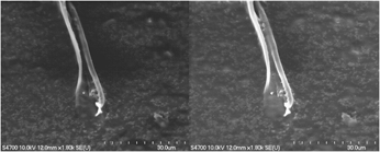
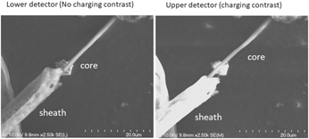
Fiber samples were collected and freeze-fractured to expose the cross section of the fibers and provide SEM images of core/sheath fiber structure. The SEM was also used to determine whether the core was conductive by scanning the sample with both higher and lower intensity electron beams and comparing the results. Under a high-intensity electron beam, insulators appear brighter because of charging at the surface, because of the buildup of electrons on the insulating material. This causes the PLLA sheath of the core/sheath fibers to appear very bright in the SEM image. Electrons are more readily removed by a conductor; thus, there is no brightening of the image with increased bean intensity. In Fig. 6, the core material is clearly exposed from the PLLA sheath. The fiber in this image was spun using the 22G/16G electrospinning needle combination and using the PEDOT:PSS nanoparticles, and freeze-fractured perpendicular to the axis of alignment. The sheath has a diameter of 6.7 µm, and the core a diameter of 1.2 µm. When the fiber was exposed to a higher intensity electron beam (Fig. 6-right), the sheath appears much brighter than under the low-intensity beam (Fig. 6-left), while the core looks unchanged and dull. The glow of the PLLA sheath compared with the PEDOT:PSS core clearly indicates an insulating sheath containing a conductive core.
SEM coaxial fibers.

The SEM images of the fibers spun with the 22G/17G electrospinning combination also indicated a core shell structure (Fig. 7). This image shows the sheath split down the center and the core in the middle. The sheath has a diameter of 4.8 µm and the core has a diameter of 1.9 µm. Direct contact probes for measuring electrical conductivity in an FE-SEM or TEM are now available and should be used in further studies to quantify the core conductivity in situ.
SEM split fiber.

Chemical and mechanical property results
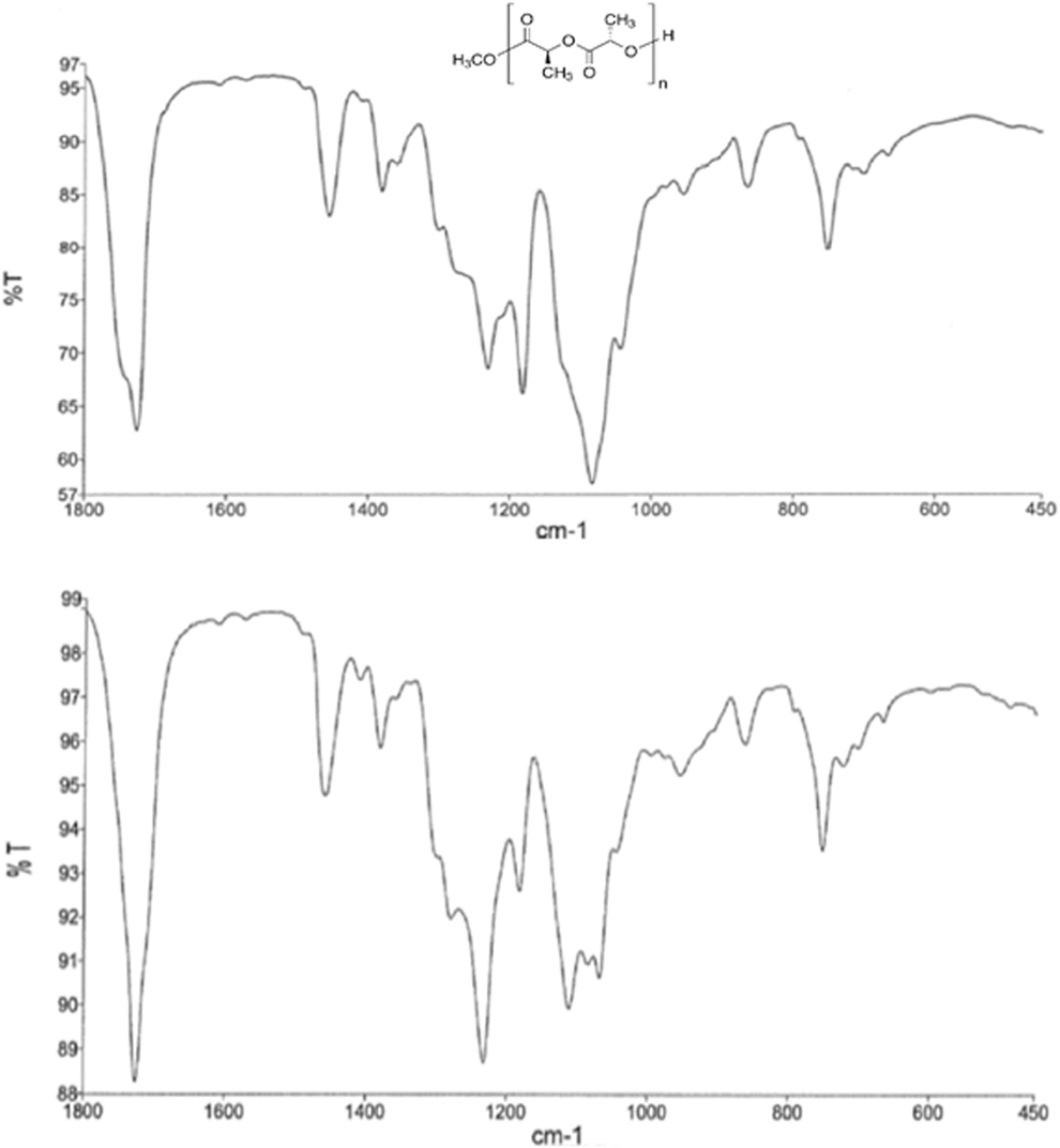
FTIR analysis was performed using a PerkinElmer Spectrum One spectrometer on the surface of both pure PLLA fibers and coaxial core/sheath fibers and their surface chemistry compared (Fig. 8). Fifty scans were performed to obtain each spectrum. The pure PLLA spectrum showed the characteristic carbonyl peak between 1800 and 1600 cm−1. There are also methyl peaks around 1300 to 1200 cm−1 and strong C–C–O and O–C–C peaks between 1150 and 1000 cm−1. The spectrum of the coaxial fiber surface shows similar peaks, with some enhanced C–H peaks around 1250 cm−1, but none of the characteristic C–S peaks indicative of PEDOT. This suggests that only PLLA was present on the surface of the coaxial fibers, and PEDOT:PSS did not occur on the surface in significant amounts. The absence of an unambiguous IR signature for PEDOT:PSS is evidence that the core is encased by the PLLA of the sheath, and that no separate single-stranded PEDOT:PSS fibers were formed.
FTIR of coax fibers.

Mechanical testing using a nanoindenter (Agilent NanoIndenter XPS) was performed on the coaxial fibers with different diameters and compared to the mechanical properties of pure PLLA fibers determined previously. The Berkovich tip makes indentations in the surface of the sample, collecting load and displacement measurements that are then used to calculate the Young’s modulus [Reference Seo44]. Pure PLLA fibers, coaxial fibers spun with a 22G/16G inner/outer spinning needle combination, and coaxial fibers spun with a 22G/17G inner/outer spinning needle combination were tested. The indentation depth was 1500 nm to maintain consistent with previous testing. Twenty points were taken per sample, over a sample area of 5 × 4, and 50 µm by 75 µm. The mechanical properties were determined using the Oliver and Pharr model [Reference Pharr, Oliver and Brotzen45].
The PLLA data were collected with a penetration depth of 1500 nm. Because of the diameter of the coaxial fibers (>3 µm), it was determined that an indentation depth of 1500 nm would be also be sufficient to collect data but would not penetrate the sample. The average modulus for pure PLLA fibers was 1.22 ± 0.19 GPa with a hardness of 0.05 ± 0.006 GPa and a density of 397.5 ± 40.3 fibers/mm. The average modulus for the smaller diameter coaxial fibers was 0.7 ± 0.04 GPa and the average hardness was 0.03 ± 0.003 GPa with a density of 53 ± 6.6 fibers/mm. The average modulus for larger diameter fibers was 0.16 ± 0.13 GPa and the average hardness was 0.022 ± 0.01 GPa, with a density of 28 ± 4.3 fibers/mm.
DRG cell cultures
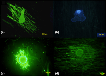
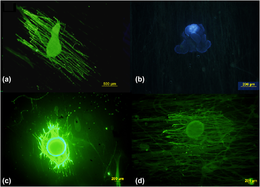
The successful use of these materials for neural tissue scaffolds depends upon their ability to promote and guide axonal outgrowth with little to no toxicity to the cell cultures. Previous research by our group demonstrated the ability of highly aligned PLLA fibers to accomplish this goal [Reference Wang, Mullins, Cregg, Hurtado, Oudega, Trombley and Gilbert7, Reference Wang, Mullins, Cregg, McCarthy and Gilbert46]. To demonstrate if a similar degree of success could be achieved with composite coaxial fibers, in vitro cell studies were performed using stage E9 chick DRG cells using the same procedures as those previous studies [Reference Hurtado, Cregg, Wang, Wendell, Oudega, Gilbert and McDonald5]. Pure PLLA fiber scaffolds were used as a control. As a control on the dopants for the coaxial fibers, DRG cultures on coaxial fibers with only oleic acid in the core (without PEDOT) and a pure PLLA sheath were conducted. Finally, DRGs were cultured on core/sheath fibers with either PEDOT:PSS and PEDOT:DBSA cores and the effect of the core material on cell toxicity and axonal outgrowth was observed. Photographs of cell cultures from each of these studies are shown in Fig. 9, where Fig. 9(a) is a 5-day cell culture on the pure PLLA control. The axons in Fig. 9(a) showed an average outgrowth of 1100 ± 220 µm. All the coaxial fibers in Figs. 9(b)–9(d) were spun using the 22G/16G combination. Figure 9(b) is a 7-day cell culture on coaxial fibers with PEDOT:DBSA nanoparticles. The axonal outgrowth here is negligible, demonstrating the toxic nature of DBSA toward the DRG cell culture. Figure 9(c) is a 5-day cell culture on coaxial fibers with PEDOT:PSS in the core. The axons of the cell in Fig. 9(c) showed an average outgrowth of 735 ± 220 µm and appear in thicker strands, possibly because of the larger fiber diameter and different surface morphology. Figure 9(d) is a 7-day cell culture on coaxial fibers with PEDOT:PSS in the core. The axons of the cell in Fig. 9(d) showed an average outgrowth of 805 ± 110 µm, comparable to the extension seen on pure PLLA fibers; but once again the axons appear in thicker strands than on the slightly smaller diameter, pure PLLA fibers in Fig. 9(a).
DRG on fibers.
Discussion
Fiber mechanical and chemical properties
In our study, the Young’s modulus was smaller for both sets of coaxial fibers than for pure PLLA. The relative thinness of the PLLA sheath around the core makes the fibers more pliable and hence allows them to bend more easily under the indenter tip. The modulus for the larger diameter fibers was smaller than the modulus for the smaller diameter fibers, because the larger sheath diameter around the core makes the fibers more flexible. This may be due to higher flexibility of the thin PLLA sheaths in the coaxial fibers, or because the nanoindenter penetration depth was on the same order as the outer sheath thickness (∼1.5 μm). The hardness was similar for all the fibers, because the same PLLA was used in the spinning of all the fibers tested and the indention depth was always the same. The standard deviations of the hardness of the two coaxial fiber samples overlapped, indicating no statistical difference between the two. For in vivo applications, it would be desirable for the mechanical properties of the fiber scaffolds to mimic the properties of the extracellular matrix (ECM) of native neural tissue; however, the modulus of the PLLA electrospun fibers is still much higher than that of natural neural tissue, which has an elasticity of 0.5–1 kPa [Reference Reilly and Engler47].
Image analysis
The combination of fluorescence images, SEM, and surface spectroscopy provide strong evidence that our electrospun fibers have a distinct core/sheath structure. Fluorescence optical imaging of the coaxial fibers with a green fluorescent core and a red fluorescent sheath, when overlaid, yields a predominately yellow image of the core, indicating the fibers were coaxial in nature. Figure 4 shows the same field of view for a sample in each color and the digital overlay. The overlay image is predominately yellow and red; however, there is almost no green to indicate exposed core PEDOT materials or separate PEDOT:PSS fibers. Any appearance of green from the core would be evidence that the core materials were exposed. Earlier, less successful studies often produced separate red and green fluorescent fibers, but under conditions that produced a stable coaxial Taylor’s cone, the separate fibers were not observed. Figure 5 shows a higher magnification of a coaxial sample spun under conditions similar to Fig. 4, but with increased contrast to highlight the image colors. This image shows separate yellow and red regions indicating that the core and shell are not simply blended together. In the detail from Fig. 5, a yellow region is seen near the center indicating the presence of both red and green dyes in the core region, with red on the edges indicating the presence of only the red fluorescing PLLA dye on the periphery. Because the PLLA refracts light well, it is difficult to see the detail of the dye distribution between the sheath and core, especially for the smaller diameter fibers. The fluorescence microscope images are not conclusive evidence for a core/sheath structure, but when combined with the other evidence from FTIR and SEM showing the absence of PEDOT in the sheath, and the coaxial morphology, the case is compelling.
For example, the FE-SEM imaging clearly shows separation of the core PEDOT:PSS and sheath PLLA, either at the ends of the fiber after freeze-fracturing or where the sheath has split, exposing the core. The FE-SEM imaging of the coaxial fibers at high and low beam strength also showed that the fibers have a conductive core with an insulating sheath (Fig. 6). This is demonstrated by the brightness of the sheath image at high beam strengths because of charging effects, versus the dullness of the core image at both high and low beam strengths because of the conductivity of the core, and thus the absence of charging. Although there are several recent articles on the electrospinning of conductive fibers [Reference Anderson, Shelke, Manoukian, Yu, McCullough and Kumbar28, Reference Lee, Bashur, Goldstein and Schmidt29, Reference Guex, Spicer, Armgarth and Glemi30], we are not aware of similar conductive core structures being reported.
Smaller diameter fibers (1–4 µm), similar in size to the axons themselves, have been shown to be best in aiding axonal outgrowth in vitro [Reference Cong, Liu and Chen43]. The diameter of the pure PLLA single fibers in this study was 2.8 ± 1.3 µm. The larger diameter (22G/16G) coaxial fibers had an average fiber diameter of 6.1 ± 2.4 µm, twice the diameter of pure PLLA fibers, whereas the smaller diameter (22G/17G) coaxial fibers had an average fiber diameter of 3.3 ± 0.9 µm. The diameters of these smaller diameter coaxial fibers fall within the standard deviation of the pure PLLA fibers. The larger fiber diameters for the coaxial fibers may not be optimal for axonal outgrowth, but the results indicate that further reducing the coaxial fiber diameter by using smaller needle sizes or adjusting other electrospinning parameters has promise.
The degree of alignment for neural scaffold materials is a key factor in promoting directed axonal outgrowth [Reference Hurtado, Cregg, Wang, Wendell, Oudega, Gilbert and McDonald5]. Optical image analysis of the alignment of our coaxial fibers showed that the overall 2σ value was relatively large for the smaller diameter fibers, at 39.4°. However, 70% of the fibers were within 10° of perfect alignment, indicating that there were a small number of cross-fibers generated during electrospinning, which unduly weighted the alignment statistics. The same was true for the larger diameter coaxial fibers. The overall 2σ was around 21°, but analysis of the deviation of individual fibers from the perfect angle of alignment showed 70% were within 8°. This again indicated the presence of a few crossed fibers, but the overall alignment was adequate for successfully directing axonal outgrowth. Both sets of coaxial fibers had a lower degree of alignment than pure PLLA fibers, which had a 2σ of approximately 10°. To attain alignment, the coaxial fibers were collected at a spinning rate much higher rate than for the pure PLLA fibers (3000 versus 1250 rpm). The higher wheel rotation rate needed for coaxial fibers may be due to the thickness of the strand pulled from the Taylor’s cone. The coaxial fibers are much thicker than the pure PLLA fibers, thus requiring more force to pull them into aligned scaffolds. The coaxial fibers also required a higher spinning voltage than the pure PLLA fibers (20 versus 17 kV) because more electrostatic force is required to overcome the surface tension in the dual droplet and distort it into a dual Taylor’s cone. The higher voltages result in more stray currents around the electrospinning apparatus, creating the opportunity for more fibers to be formed outside the axis of alignment.
DRG cell cultures
Exploratory in vitro DRG cell culture studies were performed on both the large and small diameter coaxial fibers and compared to pure PLLA fibers. When comparing the fibers containing PEDOT:DBSA nanoparticles in the core [Fig. 9(b)] versus those which contained PEDOT:PSS in the core [Figs. 9(c) and 9(d)], the difference is dramatic. The DBSA counterion in the PEDOT nanoparticles appears to hinder axonal outgrowth and to deform or kill the DRG cells, and no successful cultures were achieved after numerous trials. PEDOT:PSS coaxial fibers yielded successful cell cultures and show directed axonal outgrowth, but not quite as robustly as the single-strand pure PLLA fibers. The fluorescence microscopy photographs show less dispersed axonal outgrowth with larger diameter axon bundles extending from the DRG. This may be a result of the larger diameter of the coaxial fibers, which allow several axons to attach and grow on the surface. For fibers closer to the axon diameter, the lower surface area makes this less likely to occur. This is more evidence that smaller diameter coaxial fibers are beneficial for robust axonal outgrowth. Originally, only larger fibers spun with the 22G/16G inner/outer needle system were studied, and the larger diameter of these fibers could adversely affect axonal outgrowth. Therefore, the smaller 22G/17G inner/outer system was also used to spin fibers and the effect of coaxial fiber size on axonal outgrowth observed. The results indicate that the axonal outgrowth was somewhat better for the thinner fibers (843 μm ± 112 μm), but well within the standard deviation of the measurements for both diameter fibers.
The coaxial fibers were also not as well aligned as the single PLLA fibers, and because of the higher spinning voltages and stray currents, they contained a small number of fibers across the plane of alignment. The smaller coaxial fibers were actually less aligned (2σ = 39.4°) than the large diameter fibers (2σ = 21.6°). Misaligned or crossing fibers have been shown to significantly impede axonal extension; however, our results do not clearly differentiate whether the fiber composition, diameter, or alignment is the key factor in axonal outgrowth.
The success of these initial in vitro studies indicates that the coaxial fibers with a PEDOT:PSS core are compatible with successful culturing of neuronal DRGs, resulting in axonal outgrowth and extension comparable to pure PLLA fibers. The axonal outgrowth on our coaxial fibers occurs in larger strands than on pure PLLA, perhaps because even the smallest diameter coaxial fibers in this study may be too large to optimally aid in well-dispersed axonal outgrowth. Because of the higher voltages used, additional stray currents are generated around the spinning device, and the resulting coaxial fibers are not as closely aligned as the single fibers. The image analysis shows more random crossing fibers in the coaxial samples, perhaps enough to inhibit outgrowth or to promote axon clusters or bundles at the fiber intersections.
Conclusion
For the first time, the electrospinning of highly aligned coaxial fibers with an insulating sheath and a conductive core has been demonstrated. An electrospinning apparatus was designed to create highly aligned, coaxial microfibers, and the effect of process parameters on the fiber morphology, alignment, and mechanical properties studied. Key process and solution parameters were found to be the sheath solution composition and viscosity, the electrical properties of the core solution, the collection wheel rotation rate, and the ratio of the core-to-sheath flow rates. A novel, highly aligned core/sheath fiber structure with a conductive polymer core and an insulating sheath was successfully produced and characterized. Coaxial fibers of different outer diameters were spun using two combinations of core/sheath needles, 22G/16G inner/outer and 22G/17G inner/outer combinations. Core/sheath flow rates of 0.5/1.5 mL/h (3:1) created the most uniform coaxial fibers for this system. Coaxial fibers with an even smaller diameter may be spun by using a higher voltage, and if the rotation rate of the spinning wheel is increased, the degree of alignment of the scaffolds may also be increased.
Fluorescence microscopy, FE-SEM imaging, and ATR-FTIR surface analysis all indicated coaxial microfibers with a conductive, PEDOT:PSS core completely contained within an insulating PLLA sheath. Analysis of the surface charging from SEM images of the core/sheath freeze-fractured surface provided evidence of the conductivity of the core (Fig. 6). Although the core conductivity was not quantified in situ, the original PEDOT:PSS suspension conductivity was 54 mS/cm. The coaxial fiber process required higher flow rates and, correspondingly, higher electric field strengths. When performing DRG cell cultures in vitro, it was shown that the coaxial fibers aided in axonal outgrowth and guidance, while providing low biotoxicity. Additional in vitro DRG cell cultures studies are needed to evaluate the impact that each of these electrospinning process parameters has on the final fiber morphology and the overall fiber scaffold. Additional factors affecting neuronal growth include the core composition and diameter, the surface texture of the sheath, and the fiber density.
Methods
PEDOT particle synthesis
Poly(3,4-ethylenedioxythiophene) with poly(styrene sulfonate) was synthesized from 3,4-ethylenedioxythiophene (EDOT) and styrene sulfonic acid monomers. The procedure used an oxidative polymerization reaction with sodium sulfate as the oxidizing agent. A 1:1:2 molar ratio of EDOT:styrene sulfonic acid:sodium sulfate was the mixture used. The 1.4252 g of EDOT, 1.8371 g of styrene sulfonic acid, and 2.3848 g of sodium sulfate were added to a beaker. The liquid EDOT monomer was mixed with 25 mL of distilled water before addition to the reaction solution. The styrene sulfonic acid was mixed with 25 mL of distilled water and was also added to the reaction solution. Finally, sodium sulfate was mixed with 25 mL of distilled water before being added to the reaction solution. All three components were added to distilled water for a total volume of 100 mL of reaction solution, achieving a concentration of each reactant in solution of 0.1 M. The solution was placed in a covered beaker in a temperature-controlled bath at a constant 25 °C and left to react overnight. A resulting dark blue solid precipitate was observed at the bottom of the beaker. The product solution was filtered to collect the fine particles of the precipitate. After the product was filtered, it was rinsed thoroughly with distilled water to remove residual sodium sulfate ions from the product and allowed to dry before weighing. After drying, the product was a hard, dark blue solid. Multiple polymerizations were done to obtain enough material. The total yield of the product ranged from 53 to 69% of the original EDOT monomer.
Coaxial electrospinning procedure
Several coaxial electrospinning nozzle designs were tested for this research. In all the nozzle designs, a smaller needle, e.g., 22G (0.413 mm I.D.), was placed through the center of the nozzle to direct the core fluid. There were two separate nozzle designs that allowed for the delivery of the outer sheath solution. The first had an annular housing with a syringe needle through the center, simultaneously delivering electrical potential to both solutions. The second design consisted of two nested syringe needles with the outer needle being large enough to pass the core needle through, with potential being applied to both needles.
Using syringe needles allowed the power supply to be easily connected to both the inner and outer needles, with the needles being held in a Teflon® support to reduce stray currents and allow easier alignment of the spinning system. To further reduce stray current, a small piece of Tygon® tubing was placed over the outer needle, insulating it from the environment. The second nozzle design allowed for the most consistent spinning of coaxial fibers and the fiber diameters could be manipulated by selecting needles with different diameters. Fibers spun using a 22G/16G (16G = 1.194 mm I.D.) spinning needle pair had a significantly larger diameter, whereas the 22G/17G (17G = 1.067 mm I.D.) spinning needle combination allowed for smaller diameter fibers to be spun. Coaxial microfiber samples were spun at the previously determined flow rates for 10 min and dried in a vacuum oven at 50 °C for 30 min to evaporate residual solvent.
With coaxial spinning, the number of process parameters necessary for consistent electrospinning are much larger and include the flow rates of the inner and outer solutions, the viscosity of the sheath material, and the electrical and chemical properties of the solvents. The coaxial needle arrangement was placed with the tip 10 cm above a spinning aluminum ground electrode (1250 rpm) with a diameter of 12 cm and a width of 1.2 cm (Fig. 1). The entire apparatus is inside a Plexiglas chamber, allowing for control of the spinning environment. A Glassman high-voltage power supply was connected to the spinning needles and operated at +17 to +20 kV. The process was monitored by a microscopic video camera, allowing for visualization of the fiber being spun and assuring proper formation of a Taylor’s cone.
Viscosity testing
For coaxial spinning, the viscosity of the inner solution is not as important because it is encapsulated in the sheath. However, the viscosity of the sheath solution, or the solution in single-stranded fiber electrospinning, is a vital parameter for achieving bead-free consistent fibers and can affect the diameter of the fibers as well. Viscosity testing was done on the PLLA polymer sheath solution to determine the optimum viscosity range for spinning consistent fiber scaffolds. An SV-10 Vibro Viscometer was used to perform the viscosity testing at a frequency of 30 Hz and amplitude of 1 mm (i.e., a fixed shear rate). A 10 wt% stock solution of PLLA was made to be diluted to use for the viscosity profile. Then, 4.1427 g of PLLA were dissolved in 25 mL of chloroform to make a 10 wt% solution. The solution was placed on a combination stir/heat plate for approximately 1 h until all the PLLA was dissolved.
Image analysis
The diameter of the fibers was measured using ImageJ with the DiameterJ plug-in. The diameter of PLLA single-walled fibers, coaxial fibers spun with a 22G/16G inner/outer spinning needle combination, and coaxial fibers spun with a 22G/17G inner/outer spinning needle combination were measured and compared for 10 fibers selected from at least 12 images. The average diameter of the coaxial fibers spun with a 17G outer needle was 3.30 ± 0.96 µm. The average diameter of the fibers spun with the 16G outer needle was 6.11 ± 2.43 µm. Alignment analysis was also performed on the two different types of coaxial fibers. The smaller diameter coaxial fibers had a σ = 17.9° (2σ = 39.4°). The larger diameter coaxial fibers had a σ = 10.8° (2σ = 21.6°). This was compared to the average diameter and alignment of pure PLLA single-walled fibers. The average diameter of PLLA single-walled fibers was 2.8 ± 1.3 µm, and the fibers had a σ = 5.1° (2σ = 10.2°). Figure 3 shows optical images obtained comparing the smaller and larger fiber diameter coaxial fibers. Although the 2σ value for the smaller diameter coaxial fibers was quite large, further analysis showed 70% of the fibers were within 10° of the angle-of-alignment. For the larger diameter fibers, 70% were within 8° of the angle-of-alignment. This indicates that a small number of cross-fibers were present in both sets of samples, weighting the statistics on the overall alignment of the fibers.
DRG cell cultures
Coverslips with deposited fiber samples were sterilized with an ethylene oxide sterilization chamber. Samples were placed in a sterilization bag with a vial of ethylene oxide. The bag was purged of air and the vial was broken. The samples remained in the chamber for 12 h. Chick DRG cells were isolated from stage E9 chick embryos. The eggs were incubated at 37 °C for 9 days before isolation. The incubator was filled with distilled water supplemented with water bath cleaner. More distilled water was added when necessary. When the DRGs were isolated in accordance with the protocol established by the Institutional Animal Care and Use Committee (IACUC) at the Michigan Technological University. The DRGs were placed through Pasteur pipette on top of the fiber samples and cultured with neurobasal medium supplemented with 10 ng/mL mouse 2.5S native nerve growth factor (Thermo Fisher Scientific, Waltham, Massachusetts). The samples were incubated for 3–5 days, with the medium changed every 48 h.
Once culturing was complete, the cells were treated and stained for imaging. The culture media were removed from the plates and the samples were fixed in a formalin solution of 3.7% formaldehyde in PBS buffer for 30 min. The fixing solution was removed and cells were rinsed twice with 1 mL PBS buffer. Cells were then blocked with 1% BSA in 50 mL of fixing buffer for 1 h to prevent protein binding of the immunochemistry staining. The buffer was then removed and 50 μL solution of primary antibody TUG 1 in a ratio of 1:200 in blocking buffer was added to the cells. The samples were wrapped in Parafilm® and placed in the refrigerator overnight. The antibody solution was then drained from the samples and rinsed three times with 1 mL of blocking buffer for 5 min each. The secondary antibody, goat anti-mouse IgG antibody, was then added to the cells and kept away from direct light. A 1:200 dilution of antibody in blocking buffer was made, and 100 μL of solution was added to the samples directly over the cells. The samples were then covered with aluminum foil and left to incubate at room temperature for 40 min, and then rinsed three times with 0.2% Triton in PBS to remove excess unbound antibodies. Approximately 1 mL of solution was added to each well and each rinse lasted for 5 min. The cells were then stained with DAPI to stain for cell nuclei. A 1:1000 dilution of DAPI in PBS was made and 1 mL was added to each well. The samples were allowed to sit for 10 min before being rinsed once with PBS. The samples were mounted onto cover slides with Mountant®, sealed with nail polish, and allowed to dry for 30 min before being imaged with fluorescence optical microscopy. Statistical testing was performed on the axonal outgrowth of the in vitro cell cultures to determine statistical differences between the samples. Tukey’s test compared the average outgrowth of the different samples with each other and grouped them based on statistical similarity.