1. Introduction
When an object is lifted out of a liquid bath, it displaces and entrains a certain quantity of liquid, part of which may be eventually left on the object’s surface as a liquid film (Wilson Reference Wilson1982; Weinstein & Ruschak Reference Weinstein and Ruschak2004; Zhang, Lyu & Fan Reference Zhang, Lyu and Fan2022). The exit also induces quickly varying forces on the object that may vastly differ from the hydrodynamic load of the completely submerged object moving at the same speed, as extensively analysed for spheres (Truscott, Epps & Munns Reference Truscott, Epps and Munns2016; Wu et al. Reference Wu, Ni, Bai, Cui and Sun2017; Chang et al. Reference Chang, Myeong, Virot, Clanet, Kim and Jung2019; Wei et al. Reference Wei, Li, Lei, Li, Rivero-Rodríguez, Lin, Wang and Scheid2024). To ultimately predict the coated film characteristics and the exit forces, one needs to resolve the various stages leading to it, from the formation of a bulge ahead of the object to the gravity-induced drainage of the film as the object crosses the interface. The entire process is complex and the dynamics as a whole is not amenable to analytical predictions. This calls for experimental and numerical approaches to gain further insight into specific systems in the route of finding general conclusions. This paper aims to elucidate the main physical processes at play during water exit of a cylinder by means of direct numerical simulations. In particular, we propose predictions of both free-surface deformation and forces during the water exit of a two-dimensional (2D) horizontal cylinder.
1.1. Water exit problems
Water exit problems are ubiquitous in nature and industrial processes, and as such their range of applications is extremely wide. For instance, the quantity of liquid deposited on the surface may be of interest for the coating industry (Weinstein & Ruschak Reference Weinstein and Ruschak2004), sensor design (Liju, Machane & Cartellier Reference Liju, Machane and Cartellier2001) or stereo-lithographic printing (Tumbleston et al. Reference Tumbleston2015), while the force acting on the exiting object and the resulting dynamics may be of concern for offshore structures such as pipelines, naval engineering (boat design, sea-to-air missiles), the design of amphibious flying vessels undergoing air/water transition (Zufferey et al. Reference Zufferey, Ancel, Farinha, Siddall, Armanini, Nasr, Brahmal, Kennedy and Kovac2019; Weisler et al. Reference Weisler, Waghela, Granlund and Bryant2021) or other applications of work involving the retrieval of a structure from a liquid (Faltinsen Reference Faltinsen1993).
In contrast to water entry problems (objects impacting the liquid surface), water exit problems have received relatively little attention to date. Perhaps less appealing and more straightforward at first glance than their ‘entry’ counterpart, they come with their own load of subtle interplay that, arguably, makes them also challenging. For instance, while both classes of problems involve thin films impacting the dynamics (Greenhow Reference Greenhow1988; Vincent et al. Reference Vincent, Xiao, Yohann, Jung and Kanso2018), the role of gravity can usually be neglected for water entry problems, when it is crucial for (comparatively slower) water exit problems – in the latter case, it is even the main driver of the drainage of the coated film (Telste Reference Telste1987). Moreover, the relative slow motion of the object implies that effects at the scale of the container are likely to play a role. Finally, as expressed by Wu et al. (Reference Wu, Ni, Bai, Cui and Sun2017), the evolution of the force acting on the object during the water entry phase is often seen as an abrupt loading, versus a comparatively less abrupt off-loading for the exit phase, justifying a focus on the entry phase. However, a closer look at the exit phase reveals non-trivial and rapid load variations that are equally important to consider for structural sizing. All of these points are further illustrated in the present paper.
Accurate experimental measurements, theoretical analyses and numerical simulations of water exit problems of a rigid body all turn out to be very challenging. It is thus not surprising that most of the recent studies addressing these problems are still of a fundamental nature and take place within a canonical frame, e.g. a cylindrical (Greenhow & Lin Reference Greenhow and Lin1983; Telste Reference Telste1987; Zhu, Faltinsen & Hu Reference Zhu, Faltinsen and Hu2007; Moshari, Nikseresht & Mehryar Reference Moshari, Nikseresht and Mehryar2014; Kostikov & Makarenko Reference Kostikov and Makarenko2018) or a spherical object (Chateau & Pitois Reference Chateau and Pitois2003; Truscott et al. Reference Truscott, Epps and Munns2016; Wu et al. Reference Wu, Ni, Bai, Cui and Sun2017; Pierson & Magnaudet Reference Pierson and Magnaudet2018), subject to its own buoyancy for the majority of these studies, or moved with a controlled sequence: constant exit velocity (Telste Reference Telste1987; Greenhow Reference Greenhow1988; Gorlov Reference Gorlov2000; Wu et al. Reference Wu, Ni, Bai, Cui and Sun2017), constant acceleration (Rajavaheinthan & Greenhow Reference Rajavaheinthan and Greenhow2015; Kostikov & Makarenko Reference Kostikov and Makarenko2018).
Experimental work is still surprisingly scarce to date, and often narrow in scope or parameter range. Objects considered in such experimental studies are, for the vast majority, either spheres or circular cylinders positioned horizontally (see, for instance, Greenhow & Lin Reference Greenhow and Lin1983; Manga & Stone Reference Manga and Stone1995; Colicchio et al. Reference Colicchio, Greco, Miozzi and Lugni2009; Truscott et al. Reference Truscott, Epps and Munns2016; Wu et al. Reference Wu, Ni, Bai, Cui and Sun2017; Champougny et al. Reference Champougny, Rio, Restagno and Scheid2017). Controlling motion experimentally can turn out to be challenging and in many studies the object’s motion is driven instead by buoyancy. Only a small subset of the studies features controlled motion, usually constant velocity (Miao Reference Miao1989; Wu et al. Reference Wu, Ni, Bai, Cui and Sun2017; Champougny et al. Reference Champougny, Rio, Restagno and Scheid2017). Ranges of Reynolds number are often at one or the other end of the spectrum, either at the low end (
 $\textit{Re} \sim 1$
) (Manga & Stone Reference Manga and Stone1995; Pitois, Moucheront & Weill Reference Pitois, Moucheront and Weill1999; Champougny et al. Reference Champougny, Rio, Restagno and Scheid2017) or the high end (
 $\textit{Re} \sim 1000$
) (Greenhow & Lin Reference Greenhow and Lin1983; Miao Reference Miao1989; Colicchio et al. Reference Colicchio, Greco, Miozzi and Lugni2009; Truscott et al. Reference Truscott, Epps and Munns2016; Truscott et al. Reference Truscott, Epps and Munns2016; Wu et al. Reference Wu, Ni, Bai, Cui and Sun2017), with typical applications in the coating industry for the former and to the naval industry for the latter. There are challenges at both ends, namely the interplay of viscous effects and inertial entrainment at small
 $\textit{Re}$
and the transition linked to turbulence at large
 $\textit{Re}$
.
1.2. Water exit of an horizontal cylinder
On the theoretical front, simplified models have been developed in the potential flow limit for the deformation of the free surface due to the upward motion of a submerged horizontal cylinder, either at constant acceleration (Makarenko Reference Makarenko2003; Kostikov & Makarenko Reference Kostikov and Makarenko2018) or at constant speed (Tyvand & Miloh Reference Tyvand and Miloh1995a ). However, when pushed beyond their range of applicability, these theoretical models quickly predict non-physical interfacial deformations, showing, for example, an exaggerated flattening of the interface near the apex, which further develop into an unrealistic downward dimple (see Kostikov & Makarenko Reference Kostikov and Makarenko2018, figures 4,5). The shortcomings of these simplified models, which stem from the highly nonlinear nature of the water exit problem, thus call for direct numerical simulations.
Seminal work on the free-surface deformation during the exit of a cylinder in an inviscid fluid was first presented by Telste (Reference Telste1987) and Greenhow (Reference Greenhow1988) in separate publications by means of related methods. Following up on experimental work by Greenhow & Lin (Reference Greenhow and Lin1983), Telste’ and Greenhow’s studies examined surface deformation, pressure distribution and force evolution for a cylinder quickly accelerated to a terminal velocity. Telste’s analysis focused on early interface crossing and made meaningful comparisons to a cylinder approaching a fixed wall (low-velocity exit) or travelling in an infinite fluid (high-velocity exit). Because of the inviscid nature of the calculations, both authors were able to isolate the influence of the interface crossing on the force evolution, which they found to be resistive overall for a range of Froude numbers from 0.01 to 2. These studies also pointed out the small but noticeable effect of surface waves, both on the fluid deformation and on the resistive force. Telste’s calculations were pushed further in time by Gorlov (Reference Gorlov2000) and Moyo & Greenhow (Reference Moyo and Greenhow2000), who highlighted the near-uniform coating of the cylinder as it continues crossing the free surface.
These earlier studies focused on inviscid flows and, therefore, were not able to account for any viscous effects (most notably: wake and drag), which prevented direct comparison to experiments. Some attempts were made in that direction when computational resources started to allowed it, either by means of direct 2D or three-dimensional (3D) Navier–Stokes solvers (Zhu et al. Reference Zhu, Faltinsen and Hu2007; Colicchio et al. Reference Colicchio, Greco, Miozzi and Lugni2009; Panahi Reference Panahi2012; Moshari et al. Reference Moshari, Nikseresht and Mehryar2014), or using adapted smoothed particle hydrodynamics methods (Basic, Degiuli & Werner Reference Basic, Degiuli and Werner2014; Buruchenko & Canelas Reference Buruchenko and Canelas2017). Most notably, these improvements allowed quantitative comparisons for the force and revealed unexpectedly quick variations of the flow resistance as the object was raised through the interface. While useful to make meaningful comparisons, these studies often feature a few test cases derived from existing experiments. Particularly, no systematic exploration of the parameter space was attempted to draw general conclusions from the simulations, and more specifically for large Froude numbers, i.e.
 $\textit{Fr}\gt 2$
.
To summarise, previous theoretical, experimental and computational studies on water exit highlight several important points:
-
(i) First, high-fidelity simulations, set in a canonical frame and able to resolve all the stages of the exit, are still much needed. Ideally, the computations should resolve the strong gradients and small scales encountered in the immediate proximity of the object (a major breakdown trigger of earlier simulations; see, e.g. Telste Reference Telste1987; Greenhow Reference Greenhow1988; Gorlov Reference Gorlov2000), but should also remain sufficiently quick to allow systematic exploration of the parameter space.
-
(ii) Second, while theoretical developments can be helpful to predict short-time dynamics, they turn out to be of little help as soon as the free-surface deformation is important, for instance, when the object crosses the interface. When pushed beyond their range of applicability, these theoretical models quickly predict non-physical interface shapes.
-
(iii) Third, while some authors do mention the development of surface gravity waves at moderate Froude numbers (Telste Reference Telste1987; Tyvand & Miloh Reference Tyvand and Miloh1995a ; Liju et al. Reference Liju, Machane and Cartellier2001), they do not provide further quantitative information on their dynamics and there influence on the key aspects such as the liquid thickness above the cylinder.
-
(iv) Fourth and last, sensitivity of the interface deformation to the body motion history is usually quickly discarded, provided a sufficiently deep start is chosen (see, e.g. Liju et al. Reference Liju, Machane and Cartellier2001).
In the present paper, we present a thorough study with a systematic sweep of parameters to investigate more thoroughly the last two points.
1.3. Transient wakes
Like any object moving through a real fluid, the upward motion of the cylinder generates a wake behind it. As we emphasise in the present paper, this wake, although discarded or ignored in many studies, has a palpable influence on the water exit process as a whole, and on the coated layer thickness in particular.
The flow past a circular cylinder is a widely studied topic, with researchers showing continuing interest since seminal work by Prandtl (Reference Prandtl1925) almost one century ago. Most of the work has been focused on the established regime characterised by a regular shedding of vortices (Von Karman vortices) over a wide range of Reynolds numbers. In contrast, comparatively little attention has been directed to the study of the transient regime, e.g. resulting from the impulsive start or acceleration of the cylinder from complete rest. As a result, the characteristics of this transient regime are still scarcely documented despite a recent regain of interest (Kalita & Sen Reference Kalita and Sen2017; Lynch & Wagner Reference Lynch and Wagner2018; Wagner et al. Reference Wagner, DeMauro, Casper, Beresh, Lynch and Pruett2018; Wu et al. Reference Wu, Kinnas, Li and Wu2019a ; Chatzimanolakis, Weber & Koumoutsakos Reference Chatzimanolakis, Weber and Koumoutsakos2022).
For small and intermediate initial depths, we expect the latter to play a significant role in the exit dynamics. In the next section, we review the existing literature on the influence of initial depth, and more generally, body motion history before crossing.
1.4. Interplay between body motion history and interface crossing
To our knowledge, the literature offers little quantitative information on the interplay between initial transient and water exit. Some comments and results, however, suggest that the initial transient is an important part of the exit process and deserve a quantitative analysis.
Telste (Reference Telste1987) performed inviscid boundary integral simulations of a cylinder exiting a bath and claimed that, while the initial acceleration of a cylinder triggers the displacement of the free surface, an initial depth of
 $10$
radii was enough to ensure that the free-surface dynamics was unperturbed by the start-up sequence. Liju et al. (Reference Liju, Machane and Cartellier2001) investigated experimentally the water exit of a vertical axisymmetric object, and assessed that the minimum depth needed for the deformation to be independent of the starting depth (transient effect) was
 $10$
radii regardless of viscosity and exit speed. On the other hand, Greenhow & Lin (Reference Greenhow and Lin1983) anticipated that vortices shed by the cylinder would influence the free surface as the latter crosses the interface due to the low pressure inside the wake. Additionally, Greenhow (Reference Greenhow1988) conceded that the viscous drag on the cylinder should, in turn, be affected by the free surface during exit due to the formation of the coated film, jeopardising any meaningful comparison between experiments and (inviscid) computations. Truscott et al. (Reference Truscott, Epps and Munns2016) recorded the trajectory of buoyant spheres rising to an interface. The authors noticed that the highly reproducible oscillatory path of the spheres is a result of their wake, and that the sphere’s pop-up height after crossing the interface strongly depends on it. More specifically, they noticed that pop-up heights are significantly smaller for spheres that reach the interface in the phase of vortex shedding, and that it results in a sideway pop-up.
1.5. Objectives of the present study
Here we propose a combined theoretical and numerical approach that focuses on the fluid flow induced by the lifting of a horizontal circular cylinder out of a liquid bath. We examine the two main stages of the exit: the initial rise, characterised by the formation of a bulge at the free surface, and the film wrapping and thinning as the object crosses the interface. While we focus on the inertial regime, we also quantify the effect of the object’s wake, an unavoidable viscous effect that affects the interface deformation well before the cylinder crosses the interface. It should be emphasised that, because only 2D simulations are carried out, 3D effects are neglected. Direct comparison with experimental measurements is thus expected to show discrepancies, which should nevertheless decrease with increasing cylinder aspect ratio.
After setting the problem in § 2 and validating the code in § 3, we lay out the general picture in § 4 and then address the characteristics of the inertial surge ahead of the cylinder in § 5. Next we analyse the characteristic bulge height during the interface crossing in § 6, starting with the free-slip reference case (§ 6.1), then addressing the influence of the lateral bounding (§ 6.2), the influence of the wake (§ 6.3) and the thinning of the coated film (§ 6.4). Finally, the evolution of the vertical force during the exit is discussed in § 7.
2. Problem description
2.1. Non-dimensional parameters
We consider the 2D problem described in figure 1, consisting of a horizontal cylinder of radius
 $a=1$
vertically lifted out of a bath of liquid at a velocity
 $U$
, released from a depth
 $d$
below the free surface, in a tank of lateral dimension
 $2W$
and depth
 $H$
. In the inviscid limit, the water exit dynamics is known to be governed by inertia and gravity (Telste Reference Telste1987; Liju et al. Reference Liju, Machane and Cartellier2001); their relative effect can be expressed as the Froude number
 $\textit{Fr} = U^2 / g a$
, where
 $g$
is the acceleration of gravity. When the cylinder is initially close to the interface, the next parameter by order of importance is the starting depth
 $d$
. It is commonly assumed that transient effects do not impact the exit dynamics if
 $d$
is sufficiently large, whereas gravitational waves are triggered at the interface when
 $d$
is small. In the latter case, they can have noticeable effects on the bulge height and the hydrodynamic force (Tyvand & Miloh Reference Tyvand and Miloh1995a
; Telste Reference Telste1987). Wake characteristics are controlled by the Reynolds number, defined as
 $\textit{Re} = \rho (2a) U / \mu$
, where
 $\rho$
is the liquid density and
 $\mu$
its dynamic viscosity. For large Reynolds numbers, we expect viscosity not only to affect the wake development (growth and stability), but also to play a hindering role in the drainage phase.
(a) Problem description in dimensionless parameters: a horizontal circular cylinder of radius
 $a=1$
is lifted out of a liquid bath of initial height
 $H$
and width
 $2W$
at a constant velocity
 $U=1$
, starting from rest at a depth
 $d$
below the free surface. A bulge is formed at short times. (b) As the cylinder crosses the interface, a liquid film of quasi-uniform thickness wraps around the cylinder while draining. A symmetric wake is formed below the cylinder. Here
 $y_c$
is the cylinder vertical position, while
 $y_s$
and
 $h$
are the free-surface elevation and film thickness directly above the cylinder (
 $y_s = y_c + 1 + h$
).

All lengths in figure 1 are non-dimensionalised by the cylinder radius
 $a$
and the fluid velocity by the nominal cylinder velocity
 $U$
. Consistently, the time is normalised by the inertial time scale
 $a/U$
and the force by the inertial force scale
 $({1}/{2}) \rho S U^2$
, where
 $S = (2 a) L$
is the cross-sectional area of the cylinder in the direction of motion and
 $L$
is the cylinder length. Note that in this 2D problem,
 $L$
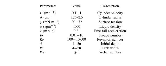
is irrelevant. In what follows, all quantities (variables and parameters) are dimensionless unless otherwise stated. The range of non-dimensional numbers considered in our work is shown in table 1, along with typical dimensional equivalents for reference.
Typical ranges of dimensional parameters (see Ashraf et al. (Reference Ashraf, Vincent, Falla, Terrapon, Scheid and Dorbolo2024)) and dimensionless numbers considered in the present work.

The effect of surface tension is disregarded in this work. This choice is supported by both physical and numerical arguments. Our work is geared towards a comparison with future in-house experiments and focuses on exit cases of macroscopic (centimetre-sized) cylinders from water and 50-cSt silicone oil at speeds between 0.1–1.3 m s−1. Taking
 $a = 25$
mm and typical parameters for water (density
 $\rho = 1000$
kg m
 $^{-3}$
, surface tension
 $\sigma = 72$
mN m−1), we can verify that the object is significantly larger than the capillary length
 $\sqrt {\sigma / \rho g} = 2.7$
mm. Moreover, the balance between surface tension and inertia can be written in terms of a Weber number,
 $W\!e = \rho a U^2 / \sigma$
, which varies between
 $4$
and
 $714$
with the above velocity range. This result suggests that, while low-velocity cases may be affected by the effect of surface tension, moderate- and high-velocity cases should not. Finally, we confirmed our order-of-magnitude approach by running simulations with and without surface tension for specific cases. We quantified and checked that the effects of surface tension on the variables of interest were negligibly small compared with all other effects already taken into account. Due to curvature calculations, these simulations with surface tension are significantly slower, right from the start, and even more so when the cylinder reaches the interface and the free surface is subjected to strong deformations, which would have effectively prevented the systematic parameter screening we propose in this work.
We anticipate, however, that surface tension may play a role in the later stages of water exit, e.g. stages that involve large local surface curvature or where volumes of fluid detach from the free surface. These events are beyond the scope of this work and inaccessible with our current numerical method that does not handle an intersecting or folding interface. To allow exploring beyond surface folding events and the later stages of exit, we developed a significantly more resource-intensive in-house method that handles topological changes. This more robust method is used to validate our present numerical method; see Appendix A.
2.2. Governing equations
The flow around the rising cylinder can be modelled with the continuity and the Navier–Stokes equations, which have been rendered dimensionless using the characteristic length
 $a$
, the characteristic velocity
 $U$
and characteristic stress
 $\rho U^2$
as
 \begin{align} \boldsymbol{\nabla } \boldsymbol{\cdot }\boldsymbol{v} = 0, \quad \partial _t \boldsymbol{v} +\left ( \boldsymbol{v} \boldsymbol{\cdot }\boldsymbol{\nabla }\right ) \boldsymbol{v} = \boldsymbol{\nabla } \boldsymbol{\cdot }\tau - \frac {1}{\textit{Fr}} \boldsymbol{e}_{\!y} \quad \mbox{in} \quad \mathcal V , \end{align}
where
 $\tau =-p \mathcal I + 2 \textit{Re}^{-1} [ \boldsymbol{\nabla } \boldsymbol{v} + (\boldsymbol{\nabla } \boldsymbol{v})^T ]$
is the stress tensor,
 $\boldsymbol{v}=(u,v)$
the velocity and
 $p$
the pressure (the factor 2 stands for the fact that the length scale is the cylinder radius whereas the Reynolds number is based on the cylinder diameter). These equations hold at any position,
 $\boldsymbol{x}$
, in the deformable liquid domain
 $\mathcal{V}(t)$
, initially of width
 $2W$
and uniform depth
 $H$
.
Let
 $\varSigma _{w\textit{all}}$
be the lateral and bottom boundaries of the container,
 $\varSigma _{\textit{cyl}}$
the interface between the 2D cylinder and the liquid, and
 $\varSigma$
the free surface. The boundary conditions on each of these surfaces are the no-penetration conditions at the tank bottom and slide walls, the no-slip condition at the cylinder surface and the stress-free condition at the free surface:
 \begin{align} \tau \boldsymbol{\cdot }\boldsymbol{n} = \frac {1}{\textit{Fr}} y \, \boldsymbol{n} \, &\quad \mbox{at} \quad \varSigma _{w\textit{all}} , \end{align}
 \begin{align} \boldsymbol{v} = \, \boldsymbol{e}_{\!y} \, &\quad \mbox{at} \quad \varSigma _{\textit{cyl}}(t) , \end{align}
 \begin{align} \tau \boldsymbol{\cdot }\boldsymbol{n} = 0 \, &\quad \mbox{at} \quad \varSigma (t) . \end{align}
Here
 $\boldsymbol{n}$
is the unit vector normal to the surface and pointing into the liquid domain. As an initial condition, the system is considered at rest, i.e.
 \begin{align} \boldsymbol{v} &= \boldsymbol{0} \quad \mbox{in} \quad \mathcal{V}(0). \end{align}
Additionally, simulations with free slip at the cylinder surface offer a reference scenario that will alternatively be used in this work to probe the influence of the wake. This free-slip condition substitutes to the no-slip condition (2.2b ) and writes
 \begin{align} \tau \boldsymbol{\cdot }\boldsymbol{n} = -p_s \boldsymbol{n} &\quad \mbox{at}\quad \varSigma _{\textit{cyl}}(t) , \end{align}
 \begin{align} \boldsymbol{v} \boldsymbol{\cdot }\boldsymbol{n} = \boldsymbol{e}_{\!y} \boldsymbol{\cdot }\boldsymbol{n} &\quad \mbox{at}\quad \varSigma _{\textit{cyl}}(t), \end{align}
where
 $p_s$
is the pressure at the cylinder surface necessary to prevent liquid penetration and, therefore, acts as a Lagrangian multiplier.
To deal with the deformable domain, the arbitrary Lagrangian–Eulerian method is used. In this method, any point
 $\boldsymbol{X}$
of the initial domain
 $\mathcal{V}(0)$
is transformed into one in the actual domain, such that
 $\boldsymbol{x}=\boldsymbol{x}(\boldsymbol{X},t) \in \mathcal{V}(t)$
and
 $\boldsymbol{X}=\boldsymbol{x}(\boldsymbol{X},0) \in \mathcal{V}(0)$
. We choose the mesh displacement
 $ \boldsymbol{q} = \boldsymbol{x}-\boldsymbol{X}$
to fulfil
 \begin{align} {\nabla }^2 \boldsymbol{q} = 0 \quad \mbox{in} \quad \mathcal V(t) , \end{align}
for which boundary conditions must be imposed on each of the domain boundaries, i.e. no deformation of the tank walls, specified velocity at the cylinder surface and a kinematic condition at the free surface:
 \begin{align} \boldsymbol{q} &= \boldsymbol{0} \qquad\, \mbox{at} \quad \varSigma _{w\textit{all}}, \end{align}
 \begin{align} \boldsymbol{q} &= \,t\, \boldsymbol{e}_{\!y} \quad \mbox{at}\quad \varSigma _{\textit{cyl}}(t), \end{align}
 \begin{align} \partial _t \boldsymbol{q} &= v_n \boldsymbol{n} \quad\, \mbox{at} \quad \varSigma (t) . \end{align}
Here
 $v_n=\boldsymbol{v} \boldsymbol{\cdot }\boldsymbol{n}$
is the normal component of the velocity. The initial condition writes
 \begin{equation} \boldsymbol {q} = \textbf {0} \quad \mbox{in } \quad \mathcal{V}(0). \end{equation}
2.3. Numerical method
The system of equations (2.1)–(2.7) is solved by means of the finite element software Comsol Multiphysics, with the moving mesh and ‘weak form PDE’ modules. Linear Lagrangian interpolants are used for the pressure and quadratic interpolants for the velocity and geometry. For the moving mesh, we use an arbitrary Lagrangian–Eulerian (ALE) formulation with a specific mesh treatment at the boundary, named the BALE method (Rivero-Rodríguez et al. Reference Rivero-Rodríguez, Pérez-Saborid and Scheid2021). The mesh is locally refined in the vicinity of the cylinder and on curved free-surface sections by setting a curvature-based criterion, leading to a uniform mesh size
 $\Delta x/a$
around the cylinder. This minimum mesh size is coupled with a growth factor
 $m$
from one layer of elements to the next. Typical parameters are
 $\Delta x/a=0.01$
and
 $m=1.04$
for the no-slip cases, and
 $\Delta x/a=0.05$
and
 $m=1.08$
for the free-slip cases at
 $\varSigma _{\textit{cyl}}$
. In addition, we set a minimum mesh size of
 $0.75a$
on the free surface to avoid excessive smoothing of the free surface when the cylinder is far (which may affect surface wave propagation). The good quality of the mesh is maintained by periodically remeshing when the mesh distortion exceeds a certain threshold (
 $20\,\%$
), resulting in a typical remeshing frequency of one event per radius travelled by the cylinder. The time stepping is done via the adaptive backward differentiation formula, with minimum order
 $2$
and maximum order
 $5$
. We performed a convergence study and checked that the results were independent of the mesh parameters, element size and time stepping, for every set of physical parameters. For the highest Reynolds number tested,
 $\textit{Re}=10\,000$
, converged results were obtained for a mesh size
 $\Delta x/a=5 \times 10^{-3}$
and a time step
 $\Delta t=10^{-3}$
. Simulations are run until topological changes (e.g. interface folding) are detected at the free surface. A single run typically takes a few hours on a standard laptop computer.
Finally, we chose to constrain the domain to a half-plane (
 $x\gt 0$
) and use the mirror condition in x = 0. This choice improves computational efficiency and allows us to explore more of the parameter space; besides, it is consistent with our focus on symmetric, transient wakes. However, it implies that the faithfulness of our simulations will degrade when, at longer times, the real wake is no longer symmetric (vortex shedding). This transition to an asymmetric flow is sensitive to physical parameters such as Reynolds number and pre-existing turbulence in the tank. For cylinders, it happens typically after 10–20 radii travelled, with evidence showings symmetric transient wakes up to 36 travelled radii (Ashraf et al. Reference Ashraf, Vincent, Falla, Terrapon, Scheid and Dorbolo2024).
3. Code validation
In this section we seek to validate our Comsol code with benchmark simulations and experiments from the literature. For clarity, we split the validation section into two subsections. In the first subsection we run tests corresponding to the canonical case of an impulsively started cylinder in an infinite medium (no free surface) at a Reynolds number between 500 and 9500, and compare it to both high-fidelity simulations and baseline experiments. In the second subsection we bring the free surface back into the picture and compare our code to water exit simulations with the free-slip boundary condition (existing literature) and to in-house numerical computations based on the particle finite element method (PFEM; see Falla et al. Reference Falla, Bobach, Boman, Ponthot and Terrapon2023).
3.1. Impulsively started cylinder
In this first set of comparisons, we seek to validate our code’s performance against well-studied cases of impulsively started cylinders in an infinite fluid medium. In the absence of the interface, the problem is set by three non-dimensional numbers, namely the Reynolds number
 $\textit{Re} = (2 a) U / \nu$
, the tank width
 $W$
and the initial distance from the cylinder to the bottom wall, that is,
 $H{-}d$
with our notation. We ran a preliminary analysis showing that this last parameter did not matter if greater than 5, and we kept that condition true for all simulations. In contrast, the tank width and Reynolds number do have a noticeable effect, and we matched them exactly when their values were available.
3.1.1. Comparison with experiments
Transient wake after impulsive start, shown by the streamlines in the cylinder’s frame of reference (left and right) and coloured vorticity contour (left). Left: our work; right: experiments from Lin et al. (Reference Lin, Hsieh, Lin and Raikar2012).
 $\textit{Re} = 500$
,
 $W =28$
.

We start with a moderate/low Reynolds number (
 $\textit{Re} = 500$
) comparison, representative of a slow water exit situation. Figure 2 compares our work (left panels) to experiments by Lin et al. (Reference Lin, Hsieh, Lin and Raikar2012) (right panels), for several time snapshots up to
 $t = 11.2$
(that is, when the cylinder travelled 11.2 radii). In spite of the eventual and inevitable loss of symmetry observed in experiments, the simulation-to-experiment agreement is excellent throughout the wake development. In particular, the bottom stagnation point in the wake, the locii of the vortex centres and the wake width all compare quantitatively well for all three time snapshots.
For larger Reynolds numbers characteristic of fast water exits, figures 3 and 4 compare our work (left panels) to long-exposure experimental snapshots from the seminal work of Bouard & Coutanceau (Reference Bouard and Coutanceau1980) (right panels), for several time snapshots up to
 $t = 5$
. Here again, the simulation-to-experiment agreement is excellent for all snapshots. We observe the faithful reproduction of even the smallest features in the wake close to the cylinder wall. It should be emphasised that the experiments of Bouard & Coutanceau (Reference Bouard and Coutanceau1980) were performed in a relatively narrow tank, i.e.
 $W=8$
, a width for which the lateral bounding has a sizeable influence on the wake development, namely a quicker wake development than the infinite-medium situation. Thus, exact matching of
 $W$
was proven necessary for relevant comparison. We note that no experimental snapshot was provided for
 $t \gt 5$
(
 $\textit{Re} = 5000$
) and
 $t \gt 3$
(
 $\textit{Re} = 9500$
). A plausible reason for this omission is the inevitable symmetry breaking of the initial 2D wake by 3D destabilisation mechanisms for these longer times.
Transient wake after the impulsive start, shown by the streamlines in the cylinder’s frame of reference (left and right) and vorticity contour (left). Left: our work; right: experiments from Bouard & Coutanceau (Reference Bouard and Coutanceau1980). Here
 $\textit{Re} = 5000$
,
 $W =8$
. The thin white circle in the left panel marks the initial position of the cylinder.

Transient wake after the impulsive start, shown by the streamlines in the cylinder’s frame of reference (left and right) and vorticity contour (left). Left: our work; right: experiments from Bouard & Coutanceau (Reference Bouard and Coutanceau1980). Here
 $\textit{Re} = 9500$
,
 $t = 3$
,
 $W =8$
.

3.1.2. Comparison with simulations
There exists a wide array of impulsive start simulations (in an infinite medium) with sufficient details to allow quantitative comparisons. For the sake of brevity, we selected for this comparison the work of Wu et al. (Reference Wu, Carvalho and Kumar2019b ), but stress that this work is a good representation of the state-of-the-art in terms of computational development for impulsive wakes; most notably, it compares favourably with the seminal computational work of Koumoutsakos & Leonard (Reference Koumoutsakos and Leonard1995). The comparison between Wu et al. (Reference Wu, Carvalho and Kumar2019b ) and our simulations shows in figure 5 a near-perfect agreement for both Reynolds numbers, 550 and 3000.
This first set of comparisons demonstrates that our numerical code faithfully reproduces the wake development following an impulsive start of a cylinder, and provides a benchmark for the wake-related effects (including forces) that will be represented henceforth.
Transient wake after impulsive start, shown by the streamlines in the cylinder’s frame of reference. Left: our work; right: simulations from Wu et al. (Reference Wu, Carvalho and Kumar2019b
) for (a)
 $\textit{Re} = 550$
and (b)
 $\textit{Re} = 3000$
, and
 $W =28$
,
 $t = 5$
.

3.2. Water exit
In order to validate our free-surface simulations, we now compare our numerical results to the less proficient literature of water exit.
Several studies in the literature feature the computationally lighter free slip case, i.e. with no shear stress at the surface of the cylinder. We present the three most relevant comparisons in the first part of this section.
In contrast, a very limited amount of literature is available with no-slip conditions at the cylinder surface. Among this limited amount, and restricting to forced motion studies (constant velocity or acceleration), no publication provided enough information or detailed enough figures to allow direct comparison. Therefore, we used instead an in-house solver (Cerquaglia et al. Reference Cerquaglia, Deliége, Boman, Terrapon and Ponthot2017; Falla et al. Reference Falla, Bobach, Boman, Ponthot and Terrapon2023) based on the PFEM (Oñate et al. Reference Oñate, Idelsohn, Del Pin and Aubry2004; Cremonesi et al. Reference Cremonesi, Franci, Idelsohn and Oñate2020) that was developed to resolve the full Navier–Stokes equations in the presence of a deformable free surface that can undergo topological changes.
For Comsol simulations, and unless otherwise specified, we used the following values for the bath width and height: W = 28 and H = 48. These values are large enough to effectively mimic an infinite bath for the sake of comparison.
3.2.1. Free slip
For these comparisons, we also use the free-slip boundary condition on the cylinder (2.4), and the largest value of Reynolds number for which we have validated the numerical convergence,
 $\textit{Re} = 10\,000$
, in order to approach the inviscid limit. Note however that, for our simulations, the viscosity, albeit small, is not zero in the bulk.
Validation of water exit with the free-slip boundary condition at the cylinder surface. Generalised vortex method simulations by Telste (Reference Telste1987) (a) and our work (b) coloured by vertical velocity; streamlines are drawn in thin grey lines. Results are shown for (a)
 $\textit{Fr} = 0.2$
and (b)
 $\textit{Fr} = 2$
. The initial depth is
 $d = 2$
.

The first comparison is with the reference work of Telste (Reference Telste1987), who studied the water exit of a 2D cylinder at a constant velocity by means of a generalised vortex method for four Froude numbers from 1/100 to 2. We selected the two largest Froude numbers,
 $\textit{Fr} = 0.2$
and
 $2$
, that both show large surface deformations. As can be seen in figure 6, our results compare very well with Telste’s computations, only showing minor differences in streamlines and free-surface location close to the points of strongest curvature and for the latest time snapshot available.
Validation of water exit with the free-slip boundary condition at the cylinder surface. Boundary integral method simulations by Gorlov (Reference Gorlov2000) (a) and our work (b), coloured by vertical velocity, superimposed on the right half of each panel. Results are shown for
 $\textit{Fr} = 0.2$
(a) and
 $\textit{Fr} = 2$
(b), for
 $d = 5$
.

The second comparison shown in figure 7 is with the work of Gorlov (Reference Gorlov2000), slightly posterior to Telste’s computations, based on a boundary integral method at the same conditions (except for
 $d=5$
) and pushing the simulations further in time. There again, the comparison with our results holds remarkably well up to the last available snapshots provided in Gorlov’s work, for
 $\textit{Fr} = 0.2$
and 2.
Validation of water exit with the free-slip boundary condition at the cylinder surface. Boundary integral method simulations by Greenhow (Reference Greenhow1988) superimposed with our work coloured by the vertical velocity at
 $y_c=0$
(left) and
 $y_c=0.5$
(right). Results are shown for
 $\textit{Fr} = 0.51$
and
 $d = 2$
.

The last comparison is with the work of Greenhow (Reference Greenhow1988) for the test case most relevant to our problem of interest, namely
 $\textit{Fr} = 0.51$
and
 $d = 2$
. Two snapshots in time (
 $y_c = 0$
and
 $y_c = 0.5$
) are shown in figure 8. Again, the agreement is overall very good. However, Greenhow’s zoomed-in figure provides an opportunity to focus on the small differences occurring at the point of largest curvature, a common feature seen in all three free-slip comparisons previously described. More specifically, the fluid neck directly below the base of the cylinder predicted by our simulations, at later times and large
 $\textit{Fr}$
, is always a little bit thinner in our results. Two possible reasons can be put forward to explain this difference: the presence of non-zero (albeit small) viscosity in our numerical simulations and the difference in resolution. Note that the surface tension is not taken into account in any of these simulations. The region in which the difference occurs presents large gradients and small scales, which suggests a high spatial resolution needed to resolve it. This second reason is supported by Greenhow’s own account of computational blowup occurring just after the last snapshot he presented. By design, our numerical approach allows a very fine meshing in this area (due to the proximity of the cylinder), which gives us confidence in the higher accuracy.
3.2.2. No-slip
To conclude our validation in the case of no-slip boundary condition on the cylinder (2.2b
), we compare our numerical approach with results obtained using another in-house solver based on the PFEM (Cerquaglia et al. Reference Cerquaglia, Deliége, Boman, Terrapon and Ponthot2017; Falla et al. Reference Falla, Bobach, Boman, Ponthot and Terrapon2023). We tested two representative set of conditions: a deep start with
 $d=10$
at an intermediate Reynolds number of 2500 and two large Froude numbers,
 $\textit{Fr} = 2$
and
 $\textit{Fr} = 10$
. Very reassuringly, PFEM and Comsol simulations are indistinguishably close. The full comparison can be found in Appendix A.
In summary, all comparisons above show very good agreements, giving us confidence in our numerical code to explore a wide range of parameters in both no-slip and free-slip conditions.
4. A typical water exit case: free-slip and no-slip
Representative half-plane (symmetric) computations for free-slip (left panels) and no-slip (right panels) boundary conditions at
 $\varSigma _{\textit{cyl}}$
. Contour of the vertical velocity for
 $\textit{Fr}=10$
,
 $\textit{Re}=10\,000$
,
 $d=7$
and
 $W=28$
. (a,b) Inertial bulging phase, (c) transition stage, and (d,e) drainage phase. The presence of a prominent wake (characteristic of no-slip conditions) induces significant changes, the most striking being a larger liquid entrainment, both above and below the cylinder. The corresponding vorticity fields and pressure fields are shown in figures 10 and 20, respectively. The thin black circle corresponds to the initial position of the cylinder.

Figure 9 shows two representative computations at the same conditions except for the boundary conditions at the cylinder surface: free-slip (left panels) and no-slip (right panels). The parameters were set to
 $\textit{Fr}=10$
,
 $\textit{Re}=10\,000$
,
 $d=7$
,
 $W=28$
and
 $H=48$
, characteristic of a large exit velocity in a wide and deep tank from a relatively shallow starting position.
The exit sequence unfolds as follows. Ahead of the cylinder reaching the free surface (figure 9
a–b), an inertial bulge forms directly above it. Barring gravity-related oscillations (studied in detail in § 5), this bulge swells continuously until the cylinder crosses the interface. Around
 $y_c=-1$
(panel c), when the cylinder top reaches the undisturbed interface level, a transition between bulging and drainage occurs; the position at
 $y_c=-1$
also serves as a reference snapshot for many measurements, such as the bulge height
 $h^*=h(y_c=-1)$
. The next stages involve strong interactions between the traversing object and the free surface: the bulge wraps around the cylinder (figure 9
c,d), creating a coated film that spreads and drains towards the bath (figure 9
d,e).
Free-slip and no-slip simulations are similar in many aspects, especially at earlier instants, but they quickly become dissimilar as the cylinder approaches the interface. The most notable difference is the formation of a strong wake for no-slip simulations (figure 9
b), whose presence is underlined by a larger-than-unity (dark red) velocity area immediately below the object. The wake progressively grows with time until the cylinder crosses the interface, at which point it typically starts shrinking quite abruptly in a Froude-dependent manner (see § 6.3 for details). In the range of parameters covered in the present work, the wake invariably consists of two large counter-rotating vortices (only one is shown in figure 9 due to only a half-plane being shown), sometimes accompanied by much smaller secondary vortices at large
 $\textit{Re}$
(as in figure 9). The nature of the flow in the vicinity of the cylinder is better shown by the vorticity fields (figure 10) that further expose the fundamental differences between no-slip and free-slip runs. The no-slip run shows strong shear layers shedding downstream and coiling in the wake, giving birth to both clockwise (red) and counter-clockwise (blue) vortices. In contrast, the free-slip run only shows a faint shear layer around and immediately below the cylinder; the presence of this small shear layer is a consequence of the small-but-non-zero viscosity used in free-slip simulations.
The strong wake, characteristic of the no-slip configuration, induces important changes in the exit dynamics. First and foremost, it greatly affects the amount of fluid the cylinder entrains as it crosses the interface; this is particularly evident in figure 9(e). Additionally, and although it primarily extends in the downstream direction (below the object), the large wake redistributes the pressure field and bends streamlines everywhere in the close vicinity of the cylinder, hence, impacting the inertial bulging.
Same as figure 9 but showing vorticity fields. The no-slip run shows strong shear layers shedding and coiling in the cylinder wake. The free-slip run only shows a small area of weak vorticity around and immediately below the cylinder.

The no-slip wake is also accompanied by a thin boundary layer on the upper half of the cylinder, whose presence is betrayed by the strong vorticity generation in this area; see figure 10. This layer of slow-moving fluid (in the cylinder’s frame of reference) increases the apparent diameter of the cylinder, and thus, naturally induces a thicker bulge height by an amount comparable to the boundary layer thickness. However, given the range of Reynolds numbers considered in this work (
 $\textit{Re}= 500 {-} 2500$
), the boundary layer thickness,
 $\propto 1/\sqrt {\textit{Re}}$
, is therefore much smaller than the bulge height, so we safely neglect its effect in the following discussion.
As these first two representative cases show, water exit is an intricate and rich sequence of events. Moreover, there are several differences between free-slip and no-slip conditions, the most striking of which is the presence (or the absence) of a wake made of two counter-rotating vortices directly below the cylinder, which in turn induces important topological changes.
We now investigate more thoroughly each step of this sequence, starting with the free-surface dynamics following the motion inception.
5. Free-surface dynamics after initial impulse (free-slip)
Inertial surge phase: (a) streamlines and free surface at
 $t=0.1$
(exaggerated surface deflection), and (b) surface elevation at the centreline
 $x=0$
, for
 $d=7$
and tank widths
 $W=7$
(teal) and
 $W=28$
(purple), representative of narrow and wide tank conditions, respectively. The inset in (b) represents a zoom of the region highlighted by the grey rectangle. The surface initially swells with a constant velocity
 $c^*$
independent of
 $\textit{Fr}$
but strongly dependent on
 $W$
in presence of lateral bounding (see figure 12 for details). For small
 $\textit{Fr}$
and large enough
 $d$
, the restoring effect of gravity results in a local maximum
 $b^*$
of surface elevation occurring at
 $t=\tau ^*$
(see figure 13 for details). The effect of lateral bounding (
 $W$
) is dominant at short times, while at longer times,
 $\textit{Fr}$
takes over as the dominant parameter. Transient surface waves are apparent for small
 $\textit{Fr}$
.

We first focus on the initial dynamics of the free surface shortly after setting the cylinder in motion. In this section we use the free-slip boundary condition at all solid boundaries: lateral and bottom walls and cylinder surface, i.e. replacing (2.2b ) by (2.4). We show that the presence of lateral walls has a noticeable effect on the surface dynamics.
When the cylinder is impulsively set in motion, the resulting dipole-like flow field provokes an upward motion of the free surface directly above the cylinder (figure 11
a). Figure 11(b) shows the corresponding surface elevation
 $y_{s}$
from the inception of the motion (
 $y_c = -d$
) to the start of the interface crossing (
 $y_c = -1$
) for an initial depth
 $d=7$
, two tank widths
 $W=7$
(narrow tank) and
 $W=28$
(wide tank) and three Froude numbers, from
 $0.1$
(slow exit) to
 $10$
(fast exit). The general trend for all conditions is a swelling of the interface as the cylinder gets closer to it. However, oscillations appear for the lower Froude number, and the dependence of the elevation to the control parameters
 $\textit{Fr}$
and
 $W$
is different at short and longer times.
At short times, the dynamics is independent of
 $\textit{Fr}$
and entirely conditioned by the tank width
 $W$
, as shown by the collapse and segregation (by
 $W$
) of all curves in the vicinity of
 $t=0$
(see inset in figure 11
b). The initial surge velocity
 $c^*$
of the interface is shown in detail in figure 12(a) for a wide range of
 $d$
and
 $W$
. The raw value indicates that the data are well fitted by
 $c^*=2.0/d^{2}$
for sufficiently large
 $W$
(or small
 $d$
). This
 $d^{-2}$
trend is seemingly in agreement with the expected
 $y^{-2}$
decay of the vertical velocity of the potential flow around a 2D object in an unbounded domain (Batchelor Reference Batchelor2000). Yet, the prefactor
 $2$
, instead of the expected
 $1$
for an infinite domain, indicates that the interface plays a role. This observation is supported by inspecting the streamlines in figure 11(a). Upper and lower half flows are not vertical reflections of each other, as it would be in an unbounded domain. In contrast to the diverging streamlines everywhere below the cylinder, representative of an unbounded flow, the streamlines above the cylinder straighten close to the free surface, which is also indicative of a slower decrease of vertical velocity in this area.
Initial surge velocity
 $c^*$
(grey lines in the inset of figure 11
b): (a) raw and (b) renormalised data in log–log scale (main) and linear–log scale (inset). At values of
 $\bar {d} = d/W$
exceeding the
 $0.5$
threshold (green dots), the surge velocity becomes more hindered by lateral bounding and the dependence in
 $\bar {d}$
changes, from an algebraic relationship
 $\bar {c} = 2 \bar {d}^{-2}$
(small
 $\bar {d}$
) to an exponential decay
 $\bar {c} = 20 e^{-3.14 \bar {d}}$
(large
 $\bar {d}$
). Both scaling laws are fitted to the data.

Initial surge: (a) raw and (b) renormalised amplitude
 $b^*$
in log–log scale (main) and linear–log scale (inset), and (d) corresponding renormalised time stamp
 $\tau ^*$
of the first maximum surge height. Line width indicates
 $W$
and shade of grey indicates
 $\textit{Fr}$
. Here T-shaped markers delineate the limit of existence of
 $b^*$
; a local maximum is only observed for a combination of large
 $\bar {d}$
and small
 $\textit{Fr}$
. At values of
 $\bar {d} = d/W$
exceeding the
 $0.5$
threshold (green dots), the surge amplitude becomes more hindered by lateral bounding, and the dependence in
 $\bar {d}$
changes from an algebraic relationship
 $\bar {c}=3.5\bar {d}^{-3/5}$
(small
 $\bar {d}$
) to an exponential decay
 $\bar {c} = 30 e^{-3.14 \bar {d}}$
(large
 $\bar {d}$
). All scaling laws are fitted to the data. (c) Schematic of surge waves for unbounded (left) and laterally bounded situations (right).

We also notice in figure 12(a) that the
 $d^{-2}$
trend is only valid for large
 $W$
and/or small
 $d$
; outside these ranges,
 $c^*$
follows instead a quicker exponential decay. Introducing the renormalised starting depth
 $\bar {d} = d/W$
and surge velocity
 $\bar {c}=c^*W^2$
, all results collapse onto a single master curve, implying the dependencies in both
 $d$
and
 $W$
have been correctly identified (figure 12
b). The algebraic and exponential trends are thus clearly separated by a small transition region occurring around
 $\bar {d}=0.5$
separating the unbounded regime (
 $\bar {d} \lt 0.5$
) where
 $\bar {c} = 2 \bar {d}^{-2}$
(or equivalently
 $c^* = 2 d^{-2}$
), from a regime dominated by lateral bounding where
 $\bar {c} = 20 e^{-3.14 \bar {d}}$
as obtained by fitting.
As time proceeds, two effects are competing: the restoring effect of gravity, which tends to curb the free-surface surge, and the promoting effect of the cylinder’s flow field (inertia), which gets stronger as the cylinder approaches the interface. For the fast motion of the cylinder (
 $\textit{Fr} \gt 1$
), inertia dominates and the surface always rises. In contrast, for slow motion (
 $\textit{Fr} \lt 1$
), gravity-induced drainage is quicker and its effect dominates. In this latter case, the elevation reaches a local maximum
 $b^*$
at a time
 $\tau ^*$
. The value of
 $b^*$
and
 $\tau ^*$
are respectively shown in figures 13(a,b) and 13(d).
Rather intuitively, a larger
 $W$
(weaker lateral bounding) and larger
 $\textit{Fr}$
(quicker rise) induce a larger surge amplitude, and so does a smaller
 $d$
(stronger flow field); as confirmed by figure 13(a). Once again, it is possible to collapse the scattered data for various
 $\textit{Fr}$
and
 $W$
using the reduced depth
 $\bar {d}$
, and renormalising
 $b^*$
by
 $\textit{Fr}^{1.5} / W^{2.5}$
, both obtained by fitting (figure 13
b). Laterally bounded and unbounded regimes appear clearly again, with a similar transition between an algebraic dependence for
 $\bar {d} \lt 0.5$
(
 $\bar {c}=3.5\bar {d}^{-3/5}$
) and exponential decay for
 $\bar {d} \gt 0.5$
(
 $\bar {c} = 30 e^{-3.14 \bar {d}}$
). Note that, unlike the surge velocity
 $c^*$
, which has no dependence on
 $\textit{Fr}$
, the initial surge amplitude
 $b^*$
shows a strong dependence to both
 $\textit{Fr}$
and
 $W$
.
We now turn to
 $\tau ^*$
, the time at which the first surging maximum occurs. Its value can be anticipated in both bounded and unbounded regimes by carrying out reasoning based on the theoretical surface wave dispersion relation (Ibrahim Reference Ibrahim2005):
 \begin{equation} 2 \pi (\lambda a) = g \left ( \frac {a}{U} \right )^2 T^2 \tanh {\left (\frac {2\pi H}{\lambda }\right )}. \end{equation}
Here,
 $\lambda$
is the wavelength,
 $T$
is the wave period and
 $H$
is the height of the (2D and unbounded) reservoir. The prefactors
 $a$
and
 $(a/U)$
account for the length and time scales used throughout this paper. Now, as suggested by figure 11(b), we assume that the local maximum of elevation occurs at a quarter wave period, namely at
 $\tau ^* = (T/4)$
. We can rewrite (5.1) in its full non-dimensional form, corresponding to the unbounded limit:
 \begin{equation} \frac {\tau ^*}{\sqrt {{\textit{Fr}} W}} = \sqrt {\frac {\pi }{8} \frac {\lambda }{W} \tanh ^{-1}{\left (\frac {2\pi H}{\lambda }\right )}} . \end{equation}
Here the wavelength
 $\lambda$
remains to be determined. In an unbounded situation, the bulge’s lateral extension is set by the starting depth such that its half-width is precisely
 $d$
(Tyvand & Miloh Reference Tyvand and Miloh1995a
,
Reference Tyvand and Milohb
). Assuming the half-width is a quarter wavelength, as suggested by figure 13(c), we get
 $\lambda = 4 d = 4 W \bar {d}$
. In contrast, in a laterally bounded situation, the wavelength is constrained by
 $W$
such that
 $\lambda = 2 W$
. In either case, given the reservoir height
 $H=48$
used in our computations, we satisfy in all cases
 $\tanh ({2 \pi H / \lambda }) \gt 0.97$
, and therefore, we assume that
 $\tanh ({2 \pi H / \lambda }) \approx 1$
(deep water approximation). Finally, we can express
 $\tau ^*$
for each situation:
 \begin{align} \frac {\tau ^*}{\sqrt {\textit{Fr W}}} &\approx \sqrt {(\pi /2) \bar {d}} \quad \textrm {(unbounded),} \end{align}
 \begin{align} \frac {\tau ^*}{\sqrt {\textit{Fr W}}} &\approx \sqrt {\pi /4} \quad \textrm {(laterally bounded).} \end{align}
Moreover, relationship (5.3) can be rewritten in its
 $W$
-independent form:
 \begin{equation} \tau ^* = \sqrt { (\pi /2) d \textit{Fr} }. \end{equation}
Figure 13(d) shows
 $\tau ^* / \sqrt {\textit{W Fr}}$
as a function of
 $\bar {d}$
, along with the theoretical predictions (thick teal and purple lines). We observe a good agreement between the computed
 $\tau ^*$
and the theoretical predictions, particularly for small
 $\textit{Fr}$
. Once again, there is a clear transition between unbounded and laterally bounded regimes occurring at
 $\bar {d} = 0.5$
.
As time progresses further and the cylinder approaches the free surface, the surface deformation above the object may or may not continue to bear the mark of the initial dynamics. This depends on both
 $d$
and
 $\textit{Fr}$
. The effect of
 $\textit{Fr}$
and
 $W$
at later times is shown in figure 11(b). We see that the effect of the tank width, dominant at short times (inset), quickly fades, while the effect of
 $\textit{Fr}$
takes over and stays dominant for the remainder of the ascent. However, for moderate and high Froude numbers (
 $\textit{Fr} = 1 - 10$
), the effect of
 $W$
is still felt, suggesting that the bulge height at later times is still affected by the initial surface wave dynamics.
The results of this section were obtained for an impulsively started cylinder, and one may wonder how they would change if the cylinder is smoothly accelerated instead. We identified that the free surface possesses an inherent time period (namely,
 $\tau$
) when responding to an infinitely short stimuli. We expect that a ‘fast-enough’ acceleration, that is, shorter than
 $\tau$
, will be felt as impulsive and the picture drawn in this section will remain strictly valid. However, acceleration slower than
 $\tau$
may change the dynamics significantly, likely with a smaller surge velocity and amplitude, and quickly vanishing free-surface oscillations.
5.1. Initial surface dynamics: conclusion
In this section we characterised the free-surface dynamics that follows the cylinder motion inception. We found that the dynamics is primarily conditioned by the tank width
 $W$
, and we identified two regimes: a regime of strong lateral bonding (depth-to-width ratio
 $\gt$
0.5) and an ‘unbounded’ regime (depth-to-width ratio
 $\lt$
0.5). Then, we identified regime-dependent scaling laws for two macroscopic observables: the initial surge velocity
 $c^*$
and the maximum surge amplitude
 $b^*$
. The maximum surge amplitude occurs at a time
 $\tau$
after the motion inception, which we predicted based on wave theory.
We expect the initial surface dynamics to have a limited impact on the free-surface behaviour if the cylinder’s starting depth is large enough, giving time for the impulsively started surface waves to settle and damp. In contrast, the initial surge is expected to have a sensible effect for a shallow starting position (small
 $d$
) or a fast motion (large
 $\textit{Fr}$
), for which an excess or deficit of bulge height is expected when the cylinder reaches the free surface. This aspect is analysed further in the next section.
6. Characteristic bulge height and free-surface shape during interface crossing
As the cylinder approaches the free surface, a prominent bulge is formed above its apex. The exact size and shape of the bulge are a function of many parameters such as the cylinder’s motion history and the fluid properties. In this section we detail the relationship between its characteristic height and the various parameters defining the problems in the general case (regardless of wake strength):
 $\textit{Fr}$
,
 $d$
,
 $W$
,
 $H$
and
 $\textit{Re}$
.
We define the characteristic bulge height
 $h^*$
as the thickness of the water layer directly above the cylinder when the cylinder’s top coincides with the undisturbed water level, i.e.
 $h^*=h(y_c=-1)$
, as illustrated in figure 9(c). From the parameter values, we expect
 $h^*$
to primarily reflect the balance between inertia and gravity-driven drainage: a faster motion (larger
 $\textit{Fr}$
) leaves less time for the drainage to take place, hence leading to a larger bulge. We also expect
 $h^*$
to depend on the starting depth
 $d$
, but in a non-trivial way: while a larger
 $d$
means a larger amount of fluid available to be displaced above the cylinder, increasing
 $d$
also increases the drainage time, and thus, promotes a smaller
 $h^*$
. Even less trivial is the influence of the wake size, a viscous phenomenon that modifies streamlines not only below the object but also above, thus affecting the bulge height. We measure and rationalise
 $h^*$
based on our understanding of transient free-surface dynamics and establish correlations between changes of wake size and increase of bulge height.
6.1. Reference case: free-slip, unbounded domain
Characteristic bulge height
 $h^*=h(y_c=-1)$
for the free-slip case and an unbounded domain and
 $\textit{Re} = 10^4$
. For large values of
 $d$
(black dashed line),
 $h^*$
follows an algebraic trend for
 $\textit{Fr} \leqslant 0.2$
and a logarithmic trend for
 $\textit{Fr}\gt 0.2$
. Surface colour indicates the distance to the best logarithmic fit for large
 $d$
(red line). The ridge betrays transient dynamics; see § 6.2. The thick faded lines mark the approximate boundaries of areas where
 $h^*$
becomes independent of either
 $d$
(continuous line) or
 $\textit{Fr}$
(dashed line). The solid line on the crest corresponds to the relation (6.2). Insets show snapshots colour coded with upwards velocity, with the initial condition d = 36.

Figure 14 shows the dependence of
 $h^*$
on the Froude number
 $\textit{Fr}$
(exit velocity) and starting depth
 $d$
. Here, in order to show the most general results, we present data using the free-slip condition and for an impulsive start in a simulated unbounded domain (
 $W=\infty$
) by using permeable side and bottom boundaries set at hydrostatic pressure (respectively placed at
 $W=28$
and
 $H=48$
). Several trends can be observed.
First, as anticipated,
 $h^*$
monotonically increases with
 $\textit{Fr}$
regardless of
 $d$
over the entire parameter space. For
 $0.2 \leqslant \textit{Fr} \leqslant 10$
and a large enough
 $d$
that we specify further below, the value of
 $h^*$
matches the logarithmic fit
 $h^*_{\textit{sf,log}} = 0.17 \log (\textit{Fr}) + 0.55$
within
 $\pm 0.02$
. The ‘sf’ subscript denotes free-slip condition at the cylinder’s surface. The corresponding region is coloured teal in figure 14. For
 $\textit{Fr} \lt 0.2$
, however, the logarithmic trend is lost and the dependence becomes instead algebraic: a reasonable fit is
 $h^*_{\textit{sf, po}w} = 0.6 \textit{Fr}^{0.45}$
. Figure 14 also reveals that
 $h^*$
is a non-monotonic function of
 $d$
, increasing from
 $d=1$
(a limit value for which the layer above the cylinder is non-existent), and reaching a plateau for
 $d=36$
at all
 $\textit{Fr}$
, indicating that the effect of transient dynamics has faded out.
We first focus on the small-
 $d$
(shallow start) region. First, the rise of
 $h^*$
for small
 $d$
is a strong function of
 $d$
, but is initially independent of the Froude number. However, segregation by
 $\textit{Fr}$
soon follows: for
 $\textit{Fr} \geqslant 10$
, the rise is seemingly monotonic until the large-depth plateau is reached, whereas for
 $\textit{Fr} \leqslant 1$
, the sharp rise is followed by a local maximum and a subsequent dip. This pattern is stretched to larger
 $d$
values as
 $\textit{Fr}$
is increased while becoming less prominent both in relative and absolute intensity. This non-monotonic behaviour reflects the presence of gravity-induced wave dynamics triggered by the impulsive start, which we have explained in more detail in § 5. Taking a step further, we propose a prediction of the locus of the local maxima. We go with the intuitive idea that, for a fixed
 $\textit{Fr}$
, the maximum value of
 $h^*$
occurs when the cylinder’s top reaches the free surface at the same time as the surface surge hits its maximum elevation, that is,
 \begin{equation} d-1 = \tau ^*. \end{equation}
The underlying assumption allowing us to write (6.1) is that the rise of the cylinder does not modify appreciably the surface wave behaviour, even as the cylinder approaches the surface. Combining (6.1) with (5.5) yields a quadratic equation; solving it produces two roots, of which only one makes physical sense (
 $d\gt 1$
):
 \begin{equation} d = m + \sqrt { m^2 - 1} ,\quad m = \frac {\pi }{4} \textit{Fr} + 1. \end{equation}
This relationship, plotted in figure 14 as a solid line, is very close to the observed crest, suggesting that this approach provides a good estimate of the starting depth that would lead to the maximum
 $h^*$
.
After reaching a local maximum and a local minimum, the value of
 $h^*$
eventually reaches a plateau as
 $d$
increases. It is useful to define the boundary separating the region of
 $d$
impacted by transient effects from the ‘deep-enough’ region where initial dynamics no longer matter. We follow the intuitive idea that the ridge-and-trough pattern (and its damping in time or, equivalently, in starting depth) scales with
 $\tau ^*$
, and we propose that the boundary lays at a value of
 $d$
that is simply twice (6.2), that is,
 $d=2(m+\sqrt {m^2-1})$
. This boundary is represented in figure 14 with a thick faded line and seems to satisfactorily separate the two regions. Beyond this limit, we expect that surface transient effects no longer impact
 $h^*$
. It is worth noting, however, that the threshold value of
 $d$
increases steadily with
 $\textit{Fr}$
; the gain is particularly pronounced for larger-than-unity
 $\textit{Fr}$
values for which
 $d \simeq ({\pi }/{2}) \textit{Fr}$
according to (6.2): as a result, the ‘deep-enough’ limit drifts to unexpectedly large values of
 $d$
for high-speed exits.
In conclusion, we have characterised the bulge height
 $h^*$
above the cylinder in a canonical setting (unbounded domain and free-slip boundary condition), and we proposed predictions of
 $h^*(\textit{Fr})$
in both low-
 $\textit{Fr}$
(algebraic) and moderate-to-high-
 $\textit{Fr}$
(logarithmic) regimes. We also rationalised the existence of a local maximum when considering increasing starting depths based on transient surface dynamics, and proposed predictions of the starting depth
 $d$
leading to this maximum, as well as the minimum value of
 $d$
needed to reach the ‘deep-enough’ behaviour for which transient wave dynamics no longer matters. Because these results have been obtained in a simplified idealised setting, we now delve into the influence of several important parameters on
 $h^*$
: lateral bounding (§ 6.2) and wake strength (§ 6.3)
6.2. Influence of lateral bounding
Effect of lateral bounding on the bulge height
 $h^*$
using the free-slip boundary condition. (a) Raw bulge height, (b) bulge height corrected for the effect of lateral bounding using
 $\delta _0$
from relation (6.4), (c) schematic, and (d) computed free surface for
 $y_c=-1$
, renormalised by
 $h^*$
in the
 $x$
direction. In a finite-size tank, volume conservation implies that the bulge (magenta area) is accompanied by a level drop
 $\delta _W$
, which in turn causes a reduction of
 $h^*$
by an amount
 $\delta _0 \approx 0.4 \delta _W$
. The bulge width is
 $w^* \approx 3 h^*$
for all
 $\textit{Fr}$
.

In § 6.1 results were obtained in an unbounded domain. However, the bulge height is affected by the lateral bounding, as figure 15(a) shows by reporting
 $h^*$
as a function of the starting depth
 $d$
for several Froude numbers and decreasing tank widths
 $W$
, from
 $W=\infty$
(unbounded) to
 $W=7$
(strong bounding). The results show that the bounding almost always plays a moderating role: a decrease of
 $W$
leads to a reduction of
 $h^*$
for almost all values of
 $\textit{Fr}$
and
 $d$
, even though marginal gains are observed in some narrow range of parameters due to transient effects. The intensity of the global reduction is shown to increase sharply with
 $\textit{Fr}$
: its effect is almost imperceptible for
 $\textit{Fr} = 0.1$
, noticeable for
 $\textit{Fr} = 1$
and strong for
 $\textit{Fr} = 10$
with up to a
 $15 \,\%$
drop at
 $W=7$
compared with
 $W=\infty$
.
We rationalise the drop in bulge height in the presence of lateral bounding and predict its magnitude
 $\delta _0$
using an argument based on volume conservation. We follow a two-step process: we first estimate the level drop
 $\delta _W$
in the bath, then we identify and use the relationship between
 $\delta _W$
and the decrease in bulge height
 $\delta _0$
. The creation of the bulge implies the elevation of a fluid volume directly above the cylinder. Due to volume conservation, this elevated volume is balanced by an average drop in level away from the bulge. The volume of fluid pushed above the initial fluid surface, assuming a roughly triangular shape, is approximated by
 $({1}/{2}) w^* h^*$
, where
 $w^*$
is the width of the bulge taken at
 $y=0$
. Making the additional assumption that the level change
 $\delta _W$
is uniform everywhere away from the bulge, the volume conservation reads
 \begin{equation} \frac {1}{2} w^* h^* = \delta _W (W-w^*). \end{equation}
This relationship involves the unknown bulge width
 $w^*$
. Free-surface profiles for various Froude numbers and various
 $W$
, shown in figure 15(d), suggest that there exists a proportionality between
 $w^*$
and
 $h^*$
, namely
 $w^* \approx 3 h^*$
. To close the reasoning, we need a relationship between the level drop
 $\delta _0$
and the level drop in the bulk
 $\delta _W$
(see schematic in figure 15
c). Measurements suggest that they are simply proportional, i.e.
 $\delta _0 \approx 0.4 \delta _W$
, and we can now rewrite (6.3) in its final form:
 \begin{equation} \delta _0 \approx 0.6 h^{*2} / (W-3h^*). \end{equation}
To check the validity of this prediction, we plot in figure 15(b) the quantity
 $h^* + \delta _0 = h^* [ 1 + 0.6 h^{*2} / (W-3h^*) ]$
as a function of
 $d$
. We observe a satisfying collapse of the data for the various lateral widths
 $W$
at each
 $\textit{Fr}$
, suggesting (6.4) provides a reliable way to predict the effect of the tank width, and hence, the lateral bounding, on bulge height.
The quadratic rise of
 $\delta _0$
with
 $h^*$
implies that the effect of
 $W$
can quickly become important as
 $\textit{Fr}$
is raised. Consequently, as the exit velocity (and
 $h^*$
) becomes larger, the minimum tank width needed for the system to behave as ‘infinitely wide’ increases quickly as well. At
 $\textit{Fr} = 10$
, a tank at least
 $13$
cylinder radii wide is necessary for the effect of lateral bounding to drop below
 $5\,\%$
, while
 $30$
radii are needed to ensure a deviation smaller than
 $2\,\%$
compared with the ‘infinitely wide’ reference value.
6.3. Influence of wake
Wake-induced surge excess. (a) Characteristic bulge height
 $h^*$
as a function of the Froude number for various starting depths, with and without wake. (b) Wake-induced surge normalised by
 $\sqrt {j^*}$
, where
 $j^*$
is the characteristic jet area. A deeper starting depth induces a larger wake at the time of crossing, which in turn promotes additional swelling
 $\delta _{{wake}}$
of the water layer above the cylinder. Here
 $W=28$
,
 $H=48$
,
 $\textit{Re}=10\,000$
.

Until now, all simulations have been performed using the free-slip boundary condition. However, in reality, the friction at the cylinder surface creates a wake (absent in the previous results), which alters the surge dynamics. The effect of the wake is thus now investigated by considering simulations with no-slip boundary conditions at the cylinder surface. Figure 16 shows the bulge height
 $h^*$
as a function of the Froude number for varying starting depths
 $d$
. When
 $d$
increases, we observe for all Froude numbers an increasing increment
 $\delta _{w\textit{ake}}$
of the bulge height with respect to the free-slip situation (red-edged symbols and red line), suggesting that the presence of the wake increases the bulge height.
Larger starting depths correlate with a larger wake size: because the cylinder starts from a lower position, the wake is given additional time to develop. Figure 17(a) shows the time evolution of the ‘jet area’
 $j$
, a representative measurement of wake size defined as the area where the vertical velocity
 $v$
equals or exceeds that of the cylinder (
 $v/U \geqslant 1$
).
Wake size and jet area (no-slip). (a) Time evolution of the jet area
 $j$
for various
 $\textit{Fr}$
(colour bar),
 $d$
and two values of
 $\textit{Re}$
, and (b) characteristic value of the jet area at the crossing,
 $j^*=j(y_c=-1)$
, as a function of
 $\textit{Fr}$
for various
 $d$
and
 $\textit{Re}$
. The jet area, proportional to the wake size, undergoes a quasi-algebraic
 $\textit{Fr}$
-independent (but
 $\textit{Re}$
-dependent) growth until the cylinder crosses the interface, followed by a quick
 $\textit{Fr}$
-dependent decay. Both the growth and the characteristic wake size exhibit a slight dependence on
 $\textit{Re}$
.

Our measurements show that during the cylinder’s submerged phase, the jet area monotonically increases with time, just as we would expect for a submerged cylinder. It is, remarkably, independent of
 $\textit{Fr}$
. We characterised the growth by fitting a
 $\textit{Re}$
-dependent algebraic relationship of the form
 $j \propto (t-\delta (\textit{Re}))^\alpha$
, where
 $\delta (\textit{Re})$
is a small
 $\textit{Re}$
-related delay. This delay reflects the fact that the wake does not immediately start growing as the cylinder starts to move. Indeed, during a short-time period, there exist a potential-like flow pattern around the cylinder; then the boundary layers on the bottom part of the cylinder gradually grow and give way to the main counter-rotating vortices Koumoutsakos & Leonard (Reference Koumoutsakos and Leonard1995).
The initial growth is substantially quicker for
 $\textit{Re}=500$
(exponent
 $\approx 0.77$
) than for
 $\textit{Re}=2500$
(exponent
 $\approx 0.68$
). Data for
 $\textit{Re}=10\,000$
, not shown in figure 17(a), closely follows the trend for
 $\textit{Re}=2500$
; however, it appears significantly noisier due to the larger influence of small vortical structures in the wake at that Reynolds number.
As a result, the characteristic jet area
 $j^*$
(the jet area at
 $y_c = -1$
) does not depend on
 $\textit{Fr}$
either, but instead bears a strong dependence on
 $d$
and almost no dependence on
 $\textit{Re}$
as figure 17(b) shows.
Following the growth, shortly after the cylinder reaches the interface (
 $y_c=-1$
), the wake growth turns into a rapid
 $\textit{Fr}$
-dependent decay, fuelled by the rapid draining of the water around the cylinder.
Taken together, these results suggest that the free surface does not influence the wake until after the cylinder reaches the interface. On the other hand, the influence of the wake on the free surface is significant: the wake bends the streamlines in the vicinity of the cylinder, both below and above, and interferes with the bulge formation. We pushed the correlation further and identified a relationship between the characteristic jet size
 $j^*$
and the surge increment
 $\delta _{w\textit{ake}}$
. Normalising the latter by
 $\sqrt {j^*}$
, we obtain an excellent collapse of the data for Froude numbers
 $\textit{Fr} \lesssim d/3$
, as illustrated in figure 16(b). The master curve is a logarithmic function of
 $\textit{Fr}$
, suggesting that the free surface is virtually insensitive to the wake size for a small exit velocity, whereas it is very sensitive to it for large exit velocities (figure 16
a). To put this result in perspective, for
 $\textit{Fr}=10$
and
 $d=36$
, up to
 $30\,\%$
of the bulge height is due to the cylinder’s wake (figure 16
a). For
 $\textit{Fr} \gtrsim d/3$
however, the data deviates significantly from the master curve and seems to reach a plateau at large
 $\textit{Fr}$
(
 $\textit{Fr}$
independent), whose level increases with
 $d$
.
In the numerical results presented above, the wake, symmetric by construction, stays attached to the cylinder regardless of the distance travelled (up to
 $36a$
). We find it important to point out that in typical experimental conditions, a stable symmetric wake is only observed for up to approximately 10–15 radii travelled. Beyond this limit, one vortex usually grows at the expense of the other (Bouard & Coutanceau Reference Bouard and Coutanceau1980; Lin et al. Reference Lin, Hsieh, Lin and Raikar2012), followed by its shedding, and the eventual transition to an alternating vortex street (von Karman vortices). Nonetheless, we believe that our results beyond this typical
 $15R$
limit are still valuable, for two reasons: (i) for large initial depths, the effect of the wake size is stronger, which allows us to verify correlations over a larger range of
 $d$
(see figure 16
b); and (ii) because this symmetrically growing wake is representative of what one would observe in the absence of finite perturbations. One could imagine that very careful experiments could maintain that symmetry state up to large values of
 $d$
, especially at moderate Reynolds numbers where viscous effects damp symmetry-breaking perturbations.
6.4. Film spreading and entrained volume (slip condition, no wake)
(a) Raw and (b) renormalised angular extent
 $\alpha$
of the liquid film, from the inertial bulging phase to the drainage phase. A transition occurs at
 $h/\textit{Fr}^{0.25}\sim 1$
, after which (i.e. for lower
 $h$
) the evolution converges to a self-similar spreading phase.

We now shift the focus to the later stage of the exit and aim to characterise with global characteristics the dynamics of the quasi-uniform liquid film spreading and thinning on the cylinder. In particular, we look for a renormalisation able to provide a global picture of the coating process. We define the liquid film as the region comprised between the cylinder apex and the point of curvature change at the base.
In figure 18 we first look at the angular extent of the film
 $\alpha$
for Froude numbers comprised between 0.02 and 2. Panel (a) shows the raw data as a function of the film thickness at the apex
 $h$
. We use the film thickness
 $h$
instead of
 $y_c$
as a measurement of drainage progression; as a result, time goes from right to left. Far ahead of the crossing, when
 $h \sim 2{-}3$
, all
 $\alpha$
are varying little in time and seemingly converge to a single value around
 $0.5$
rad. A constant angle is a synonym of a bulge whose lateral dimensions are proportional to the object’s depth, consistent with the literature.
As time progresses, the general trend is an accelerating spreading of the liquid film; that acceleration is progressive and earlier for large Froude numbers (top curves) and much sharper for small Froude numbers (bottom curves), consistent with the rapid free-surface modifications observed when the cylinder approaches the free surface at small
 $\textit{Fr}$
. Renormalising both the film thickness and the angular extent by
 $\textit{Fr}^{1/4}$
reveals a self-similar spreading behaviour in the later phase (figure 19
b). Moreover, we observe for all
 $\textit{Fr}$
a sharp transition from a slow progressive spreading (earlier times) to a quickly accelerating spreading (later times), happening around
 $h/\textit{Fr}^{0.25} \simeq 1$
for all
 $\textit{Fr}$
. We interpret this behavioural shift as a transition between a bulging regime and a drainage/spreading regime.
(a) Raw and (b) renormalised non-dimensional volume
 $\varOmega$
of the film during the drainage phase. The renormalisation allows a prediction of the film volume eventually deposited on the cylinder for all Froude numbers:
 $\varOmega ^* \approx 0.22 \textit{Fr}^{1/2}$
.

To gain further insight into the changes occurring in the liquid film, figure 19 shows the evolution of the volume
 $\varOmega$
contained in the liquid film, measured as the integration of
 $h(\alpha )$
, from
 $\alpha = 0$
to
 $\alpha _C$
, where
 $\alpha _C$
is the angular position of the curvature change.
Raw results of
 $\varOmega$
vs
 $h$
are shown in (figure 19
a) for Froude numbers comprised between 0.02 and 2. We observe that, for a given
 $h$
, increasing the Froude number leads to a moderate increase of
 $\varOmega$
, suggesting a larger Froude is associated with a thicker film.
Renormalising both the film thickness and the film volume by
 $\textit{Fr}^{1/4}$
and
 $\textit{Fr}^{1/2}$
, respectively, we uncover a self-similar drainage behaviour (figure 19
b). Extrapolating the master curve to
 $h = 0$
leads to a single value of
 $\varOmega / \textit{Fr}^{1/2} \approx 0.22$
, which can be interpreted as an approximation of the volume coated on the cylinder; strictly speaking, the latter would be
 $\varOmega (\alpha = \pi )$
, which would correspond to a slightly different
 $h$
for each
 $\textit{Fr}$
.
As a final note, let us note that these results were obtained with the free-slip condition on the cylinder. We made no attempt to extend these results to no-slip cases, and we expect the results to be noticeably different due to the importance of viscous effects in thin layers.
6.5. Free-surface shape during crossing: conclusion
In this section we characterised the bulge height and interface shape during interface crossing. First, we laid out a map of the characteristic bulge height
 $h^*$
as a function of the Froude number
 $\textit{Fr}$
and initial depth
 $d$
, which we rationalised by making use of findings from § 5. This map allows us to extract scaling laws and discriminate a window of
 $\textit{Fr}$
,
 $d$
where initial dynamics still affect the free-surface dynamics when the cylinder reaches it. We also quantified and modelled the influence of the bounding
 $W$
, which induces a measurable liquid depletion above the cylinder. Most importantly, we identified the leading role of wake size in setting the characteristic film thickness above the cylinder, characterised its growth (rise and fall) and assessed its effect. Finally, we analysed the spreading of the liquid film during interface crossing, and we were able to propose a prediction of the volume of liquid coating the cylinder after crossing.
7. Force on the cylinder during interface crossing
Pressure fields and streamlines obtained with free-slip (left panels) and no-slip conditions (right panels) for the same case and time stamps as in figure 9:
 $\textit{Fr} = 10$
,
 $d = 7$
,
 $\textit{Re} = 10\,000$
,
 $W = 28$
. Colour codes for dynamic pressure
 $p+\rho (1/\textit{Fr})y$
. In no-slip simulations (right panels), the presence of the wake is characterised by low-pressure zones moving and developing underneath the cylinder. The thin circular black line indicates the initial cylinder position.

Finally, we now consider the force acting on the cylinder during the interface crossing.
In its most general form, the force on the cylinder can be expressed as the sum of the pressure drag
 $F_{\!p}$
and the friction drag
 $F_{\!f}$
(Koumoutsakos & Leonard Reference Koumoutsakos and Leonard1995). The pressure drag and friction drag in the vertical direction can respectively be expressed as
 \begin{align} F_{\!p} &= \int _{\textit{cyl}}^{} p(\theta ) \boldsymbol{n} . \boldsymbol{e}_{\!y}, \end{align}
 \begin{align} F_{\!p} &= \int _{\textit{cyl}}^{} (2/\textit{Re}) \omega \boldsymbol{n} . \boldsymbol{e}_{\!y}, \end{align}
where
 $p$
is the total pressure,
 $\omega$
is the vorticity,
 $\boldsymbol{n}$
is the outward unit vector attached to the cylinder surface and
 $\boldsymbol{e}_{\!y}$
is the vertical unit vector. As figure 20 illustrates, the pressure field in the neighbourhood of the cylinder strongly depends on the boundary conditions at the cylinder surface. For free-slip simulations, the flow and pressure fields approximately retain an up–down symmetry until the cylinder reaches the interface. Conversely, for no-slip simulations, the recirculation past the cylinder induces a pair of low-pressure areas directly below it, generating what is commonly referred to as pressure drag. This dominant pressure drag is supplemented by normal and tangential viscous stresses. Tangential stresses are zero by construction when using the free-slip condition on the cylinder and small (but not negligible) when using the no-slip condition. Normal stresses, on the other hand, are very small in both free-slip and no-slip conditions due to the large Reynolds number.
We first detail the main characteristics of the force evolution for free-slip cases, then turn to no-slip simulations to single out the contributions of both the large vortical wake on one hand and the interface crossing on the other hand.
7.1. Free slip
(a) Evolution of the force acting on the cylinder at
 $\textit{Fr} = 0.1$
, 0.2, 1, 5 and 10, and (b,c) typical pressure fields for
 $\textit{Fr} = 0.1$
and 10 during interface crossing under slip conditions, all other parameters being identical to figure 20. The flat-interface (loss of) buoyancy (7.4) is represented as solid thin lines for reference for each
 $\textit{Fr}$
. Results from `no interface’ simulations (simulations where the cylinder stays submerged and far from the free surface) are also represented with a thick line for reference. The inset in (a) presents renormalised data using the buoyant force as scale instead of the dynamic force. Squares indicate occurrences of free-surface folding and halting computations. Arrows denote the intensity of the net downward (blue) or upward (green) force felt by the cylinder.

In this section, tangential viscous stress and, thus, skin friction drag are zero as a result of the free-slip condition on the cylinder.
Consequently, we choose to follow a completely inviscid approach and simply define the vertical force
 $F$
as the integral of the dynamic pressure,
 $p_{\textit{dyn}} = p + \rho y / \textit{Fr}$
. Making use of the left–right flow symmetry of the free-slip condition and following the convention that a resistive force (i.e. a force acting vertically downwards) is positive, the force per unit length in the transverse direction reads (Telste Reference Telste1987)
 \begin{equation} F = 2 \int _{0}^{\pi } p(\theta ) \cos {(\theta )}\, {\rm d}\theta + \frac {\pi }{\textit{Fr}}. \end{equation}
Using this definition, a submerged cylinder at rest experiences no force (
 $F=0$
), while a dry cylinder outside the bath is subjected to a downward force equal to the buoyancy of the immersed cylinder, that is,
 $F = \pi / \textit{Fr}$
in our non-dimensional framework. Now, assuming that the cylinder is pulled out of the bath in a quasi-steady fashion and that the interface remains flat and pinned at
 $y_c = 0$
, the resistive force felt by the cylinder during interface crossing can be estimated as the complement of the buoyancy on the wet area:
 \begin{align} F_b (y_c) = \frac {\pi }{\textit{Fr}}\! \left [ 1 - \frac {1}{\pi }\! \left ( \arccos (y_c)-y_c \sqrt {2(1-y_c)-(1-y_c)^2} \right ) \right ]\!, \quad -1 \leqslant y_c \leqslant 1. \end{align}
This baseline is represented by thin solid lines in figure 21(a). It corresponds to the force evolution we expect for an infinitely slow cylinder crossing the undisturbed interface (no liquid entrained by the cylinder, neither below or above).
Figure 21(a) presents the computed force evolution for five representative cases of cylinder exit at finite speed, from
 $\textit{Fr} = 0.1$
to
 $10$
. As expected, the force
 $F$
is vanishingly small when the cylinder is deep enough. Moreover, when the cylinder is outside the bath, well past the interface crossing, the force eventually settles to the expected value of
 $\pi / \textit{Fr}$
for a dry cylinder (see inset), at least for computations that were able to run that far (interface folding halts the runs at smaller Froude numbers; see figure 21
b). Also note that in our simulations the cylinder is always covered by liquid (at the least by a very thin layer), in contrast to the underlying assumption behind (7.4).
Between these two extreme points in time, figure 21(a) immediately makes clear that both small and large Froude cases show substantial differences to the hydrostatic reference (7.4): small Froude values are associated with a relative excess of resistive force at a given
 $y_c$
, while large Froude values show instead a deficit during crossing. This is further exemplified by renormalising the force by
 $\pi /\textit{Fr}$
, which sets the buoyancy as the reference force (inset of figure 21
a). A second general remark is that, while the terminal value of
 $\pi /\textit{Fr}$
is met starting at
 $\textit{Fr} \simeq 1$
, larger-than-unity
 $\textit{Fr}$
cases reach this terminal value with a delay that appears to increase with
 $\textit{Fr}$
. We now take a closer look and lay out the physical mechanisms behind these variations.
For small Froude numbers (
 $\textit{Fr} \leqslant 1$
), the force is nearly always larger than the hydrostatic reference (7.4). We rationalise this overall force excess by invoking two distinct contributions. Firstly, in the earlier stages of the exit, the free surface resists deformation due to gravity (dominant for that
 $\textit{Fr}$
range) and pressure builds up in the region between the cylinder and the surface (figure 21
b), inducing an overall increase of resistance prior to the cylinder reaching the interface. This is analogous to the case of a cylinder approaching a slip wall. This effect was previously identified by Telste (Reference Telste1987); see figure 9 and accompanying text in that reference. Secondly, during the late stages of the exit, inertial effects draw the free surface downwards on both sides of the cylinder, which only leaves a thin, dynamically inert film on the cylinder (last panel of figure 21
b). The loss of buoyancy thus occurs comparatively earlier (at a smaller
 $y_c$
) than for a quasi-static exit, and contributes to a comparatively larger force in these late stages. Past the simulation breakdown point, we expect the force level to reconnect with the ‘dry’ reference with no or little overshoot, just as we see for the
 $\textit{Fr} = 1$
case.
For larger Froude numbers, the force evolution also deviates from the hydrostatic reference (7.4). Perhaps counter-intuitively, the resistance decreases as
 $\textit{Fr}$
or velocity increases. We attribute this striking change of behaviour to a favourable net top-to-bottom pressure difference setting around the cylinder at a high Froude number. This pressure gradient is driven in part by a relative pressure drop ahead of the cylinder that we impute to a thinning layer: as the amount of fluid pushed forward by the cylinder decreases, so does the pressure needed to sustain the fluid’s outward motion. This gradient is also fuelled by the pressure increase below the cylinder, as highlighted in figure 21(c). This boosting effect becomes very strong for large Froude numbers: around
 $\textit{Fr} = 5$
, it cancels out the buoyancy loss during the crossing phase (zero average force from
 $y_c = -1$
to
 $y_c = 1$
), and at
 $\textit{Fr} = 10$
the cylinder now experiences an assisting force of the same order as the buoyancy loss!
To our knowledge, this favourable effect has never been identified. We hypothesise that this is due to the limited range of Froude numbers considered in previous controlled studies of water exit or to a lack of appropriate renormalisation of the force data. Indeed, renormalising force data based on the inertial force (such as in the main plot in figure 21
a), makes the high-
 $\textit{Fr}$
force changes look deceptively small compared with the low-
 $\textit{Fr}$
ones. Additionally, the effect can be partially obscured by wake-induced drag, as we show in § 7.2.
7.2. No-slip
(a) Evolution of the force acting on the cylinder at
 $\textit{Fr} = 0.08$
, 0.33, 1.3, 5.22 and 10, and (b,c) typical pressure fields for
 $\textit{Fr} = 0.08$
and 10 during interface crossing under a no-slip condition at
 $\textit{Re} = 500$
, all other conditions being identical to figure 20. See figure 21 for full caption.

We now characterise the force during interface crossing for no-slip simulations. The major difference in this case is the development of a prominent wake downstream of the cylinder, as emphasised by the side-to-side comparison of figure 20. The presence of this strong wake significantly affects the pressure acting on the cylinder’s surface, and thus, induces important changes for the vertical force. Most notably, the pair of large symmetric vortices directly in the cylinder’s wake creates a low-pressure area below the cylinder (shown in figure 22
b,c). As a result, the net resistive force quickly rises, reaching a first maximum (around
 $y_c=-4$
for all
 $\textit{Fr}$
values) before plummeting to smaller values (figure 22
a), in stark contrast to the flat start of the ‘free-slip’ behaviour. A second contribution to drag is the skin friction arising from the no-slip boundary condition at the cylinder’s surface; this contribution is smaller, but nonetheless present over the range of Reynolds numbers tested in this work (
 $\textit{Re} = 500 {-} 10\,000$
).
Closer to the interface crossing, several phenomena take place simultaneously. First, in a trend similar to the free-slip simulations (see § 7.1), the force evolution for small Froude numbers (
 $\textit{Fr} = 0.08$
and
 $0.33$
) loosely follows the loss of buoyancy occurring around interface crossing, with a sharp rise of resistive force starting shortly before
 $y_c=-1$
. Conversely, for larger Froude numbers, the loss of buoyancy is barely noticeable in the force evolution: indeed, for the
 $\textit{Fr} = 5.22$
and
 $10$
cases, the cylinder experiences a large and steady decrease of force before and across the
 $y_c = 0$
region (inset). At first glance, this decrease is not necessarily the result of interface crossing. For a submerged cylinder, as the wake grows, the low-pressure area is slowly pushed away from the cylinder’s surface, weakening its contribution to drag. Yet, this explanation is insufficient. In figure 22(a) we plotted in faded lines the drag corresponding to simulations for which the free surface is far enough to not play any role in the force evolution, simulating a submerged cylinder. Looking at the inset of figure 23(a) whose renormalisation by
 $\pi /\textit{Fr}$
better separates various
 $\textit{Fr}$
, we notice that indeed the natural evolution of the wake is only responsible for a moderate force drop, compared with the steep total drop in the presence of an interface. The mechanism at play is suggested by wake size measurements of figure 17(c): as the cylinder approaches the free surface, the wake growth stalls and sharply reverses, and the low-pressure areas are pushed further away (not shown): as a consequence, the drag sharply decreases. Lastly, the inertial and free-slip mechanism described in § 7.1 is still expected to play a role, and one could wonder about its relative contribution to the total force drop.
Net downward force excess due to interface crossing under the no-slip condition for
 $\textit{Fr} = 0.08$
, 0.33, 1.3, 5.22 and 10, and compared with the corresponding free-slip case for
 $\textit{Fr} = 5.22$
and
 $10$
(inset). All other parameters are identical to figure 22. The force reference is that of a submerged cylinder moving at the same speed. Wake weakening shortly before and during the interface crossing is responsible for an important drop of force during interface crossing.

In order to gauge more precisely the net effect of the interface crossing, and compare it to the free-slip case, we represent in figure 23 the next force excess
 $\Delta F$
between a submerged case and an interface-crossing case, both in no-slip conditions. As anticipated, the interface only starts to have an impact a few radii before the cylinder reaches it, in a fashion similar to the free-slip case for small Froude numbers (see figure 21): a sharp rise loosely matching the theoretical buoyancy loss variation. Large-Froude-numbers cases also share the similarity that the force is decreasing significantly during crossing; however, the comparison stops there.
The inset figure presents the renormalised force excess
 $\Delta F / (\pi / \textit{Fr} )$
, as well as the force evolution for the free-slip cases from figure 21 in faded lines (only shown for
 $\textit{Fr} = 5.22$
and
 $10$
for clarity). We emphasise that this comparison makes more physical sense for
 $y_c\lt 1$
, when the free-surface location is comparable between a free-slip (vanishingly small wake) and a no-slip situation. Regardless, the results show that the contribution of wake-related effects is large, overpowering that of the free-slip effect identified in § 7.1.
Finally, to support the generality of these observations, we present in figure 24 the force evolution for various
 $\textit{Re}$
from
 $500$
to
 $10\,000$
and for two values of
 $\textit{Fr}$
,
 $1.3$
and
 $10$
. We also choose a deeper start for these simulations (
 $d = 14$
vs
 $d = 7$
) in order to capture more details during the immersed phase.
Evolution of the force acting on the cylinder for various
 $\textit{Re}$
, two representative Froude numbers
 $\textit{Fr} = 1.3, 10$
and
 $d = 14$
, all other parameters are identical to figure 22. Data for different
 $\textit{Re}$
at a given
 $\textit{Fr}$
show similar variations, but large oscillations are present for
 $\textit{Re} = 10\,000$
due to wake instabilities. Inset shows the dynamic pressure fields near the cylinder for one representative pair of successive maximum and minimum downward forces; note the growing distance from the main low-pressure system to the cylinder surface (green arrows). Like for shallower start cases, the interface starts to play a role around
 $y_c = -5$
, after which segregation by
 $\textit{Fr}$
occurs.

Reynolds number
 $500$
and
 $2500$
cases have very similar time variations, the
 $\textit{Re} = 500$
case being smoother (due to viscous damping) and with substantially larger values (due to larger skin friction). Reynolds number
 $10\,000$
cases, however, show large, virtually undamped oscillations, evidence of a chaotic wake. Yet, seeing through these oscillations, one can read an underlying evolution close to the
 $\textit{Re}=2500$
case, characterised by a local maximum a few radii after start-up followed by a steady drop that accelerates around
 $y_c = 0$
. Segregation by
 $\textit{Fr}$
occurs around 3–5 radii before interface crossing for all cases.
Taken together, these observations suggest that the mechanisms leading to force change, identified and rationalised for
 $\textit{Re} = 500$
and
 $d=7$
, are relevant throughout the entire range of parameters explored in our work.
7.3. Force evolution through interface crossing: conclusion and applications
In this section we analysed the resistive force felt by the cylinder as it rises, approaches and crosses the interface, starting with the free-slip cases (§ 7.1) and then the no-slip cases (§ 7.2). Low and intermediate Froude cases generally follow loss-of-buoyancy pattern, with a sharp rise followed by a plateau. For large Froude numbers, we observe a radically different picture: a pronounced decrease of resistive force during interface crossing, present in both free-slip and no-slip conditions, but stronger in no-slip conditions due to the wake being stripped away during crossing. This conclusion is applicable to the entire parameter range.
The striking force boost during interface crossing is foreseen to be fairly general. Specifically, it is expected to hold (at various degrees) for any bluff or streamlined object and should play an important role in situations where the wake (pressure) drag is relatively small. Such a situation can arise, for instance, when the wake is only given little time to develop (e.g. for objects starting close enough to the interface) or when the object is travelling at Reynolds numbers past the drag crisis threshold (
 $\textit{Re} \approx 3\times 10^5$
for a sphere, Van Dyke Reference Van Dyke2008). This positive contribution is expected to play a role in various fast exit situations, for instance, the pop-up of buoyant spheres (Bourrier, Guyon & Jorre Reference Bourrier, Guyon and Jorre1984; Truscott et al. Reference Truscott, Epps and Munns2016). In this situation, we expect interface crossing at large Froude numbers to show unusually large pop-up heights, which is precisely what the authors observe (Truscott et al. Reference Truscott, Epps and Munns2016). We hypothesise that the effect contributes to this anomaly.
8. Conclusion
We propose a numerical study of the water exit of a 2D horizontal circular cylinder in the inertial regime, characteristic of fast water exit events. After validating our novel numerical code, we focused on four interconnected features of the water exit: (i) initial free-surface dynamics following the motion inception, (ii) free-surface bulging when the cylinder reaches the undisturbed interface, (iii) liquid deposition on the cylinder’s surface during the crossing, and (iv) the force felt by the cylinder throughout the water exit.
We showed in § 5 that initial free-surface dynamics is rich and very sensitive to some experimental parameters. In particular, lateral bounding is crucial: we identified a clear transition occurring for a reduced depth
 $\bar {d} = d/W$
(where
 $W$
is the bath half-width) around 0.5. Dynamics is sensitive to the reduced depth on both sides of this threshold, but above the latter, surging velocity and the amplitude’s dependency on
 $\bar {d}$
dramatically change in favour of a faster decay. We were also able to propose a semi-analytical prediction of the initial surge: amplitude and time of occurrence based on the wave dispersion relation.
In § 6 we then focused on a characteristic feature of free-surface deformation during the crossing, namely the bulge height
 $h^*$
when the cylinder just brushes the undisturbed water line level (
 $y_c = -1$
). In the first fundamental approach, we investigated a quasi-inviscid situation using the ‘free-slip’ boundary condition on the cylinder. We showed that
 $h^*$
is a strong and monotonic function of the Froude number, but also a non-monotonic function of the starting depth
 $d$
; finally, it also depends on lateral bounding
 $W$
. We linked the non-monotonic
 $d$
dependency to the initial dynamics explored in § 5 and rationalised the
 $W$
dependency with a volume conservation-based argument.
Building upon this fundamental result, we then investigated the ‘no-slip’ case and compared it to the ‘free-slip’ case. We showed that the bulge height
 $h^*$
is the sum of two parts: a ‘free-slip’ contribution, characterised previously, and a vortex-induced contribution that arises from the bending of streamlines in the vicinity of the cylinder. The wake-induced increment becomes proportionally larger as the Froude number increases, and was shown to be directly related to the wake size at
 $y_c = -1$
. To close the loop, we then characterised the wake size evolution from the start and beyond the interface crossing; in particular, we proposed a scaling law describing the wake growth prior to reaching the interface.
To complete our investigation on free-surface shape during the crossing, we investigated liquid deposition by characterising the time dependence of angular coverage and deposited volume. We identified a self-similar behaviour and a bulging-to-drainage transition, made apparent by representing data as a function of the film height
 $h$
at the apex and normalising by a power of Froude (
 $\textit{Fr}^{1/4}$
). Following the same analysis framework, we evaluated the volume
 $\varOmega$
deposited on the cylinder and proposed a renormalisation allowing the prediction of the liquid volume deposited on the cylinder:
 $\varOmega \approx 0.22 \textit{Fr}^{1/2}$
.
Finally, in § 7 we investigated the resistive (downward) force during exit from the point of view of the cylinder. Again, we started with the quasi-inviscid free-slip case as a reference. For a small exit velocity (small
 $\textit{Fr}$
), our result corroborates existing literature results, showing a sharp increase driven by several factors including an increased pressure in the liquid region between the cylinder and the free surface. However, raising the Froude number allows us to uncover an unexpected effect: a large exit speed (
 $\textit{Fr}\gt 5$
) results in a momentary upward force boost of the cylinder’s motion through the interface.
Reintroducing the wake into the picture does not suppress this effect, but instead introduces a supplementary force drop during interface crossing that is driven by wake weakening and wake distancing. While this vortex-related effect is comparable in strength to the cumulative free-slip effect, it is not as strong as to reverse the overall force sign (i.e. still providing an actual boost) even for the largest Froude numbers considered here. Yet, even a temporary force drop this strong could have noticeable effects, for example, on the pop-up height of a freely moving buoyant object.
To extend this work towards longer times (e.g., times well beyond crossing), one possible direction is to develop a numerical method that takes into account topological changes, such as intersection and folding free surface. Indeed, interface folding currently causes our simulation to stop prematurely for small
 $\textit{Fr}$
. Towards that goal, we are currently improving the PFEM (which is used in the present paper for validation) to handle topological changes such as interface folding and drop formation.
For these longer simulations, however, surface tension will need to be included, as it is expected to become locally important due to the large curvature of the free surface observed in some locations close to the cylinder. Additionally, capillarity becomes a major player for long-time drainage dynamics around the cylinder (Eghbali, Djambov & Gallaire Reference Eghbali, Djambov and Gallaire2024). This calls for strong numerical optimisation as we anticipate these simulations to be computationally intensive due to costly curvature calculations. We foresee, however, that surface tension will have no global impact on the force and the overall free-surface shape given the large sizes considered (larger than the capillary length).
Lastly, we should mention that real-life experiments of a constant-velocity cylinder exit usually feature an acceleration period. While the study of such a parameter falls outside the scope of this work (due to its possible coupling with nearly all the other aspects discussed here), we expect it to have a small impact overall on the characteristics of the crossing itself, as long as the acceleration period remains short with respect to the submerged phase.
Acknowledgements
The financial support of the Belgian Fund for Scientific Research under research project WOLFLOW (F.R.S.-FNRS, PDR T.0021.18) is gratefully acknowledged. S.D. and B.S. are FNRS senior research associate and research director, respectively.
Declaration of interests
The authors report no conflict of interest.
Appendix.
Because no benchmark simulation combining interface crossing and no-slip condition (that is, with a large wake) could be found in literature, we complete our validation by comparing our numerical approach with results obtained using another in-house solver based on the PFEM (Cerquaglia et al. Reference Cerquaglia, Deliége, Boman, Terrapon and Ponthot2017; Falla et al. Reference Falla, Bobach, Boman, Ponthot and Terrapon2023). We chose two test cases most relevant to the present work: a deep start with
 $d=10$
at an intermediate Reynolds number of 2500 and two large Froude numbers,
 $\textit{Fr} = 2$
and
 $\textit{Fr} = 10$
, as shown in figures 25 and 26, respectively.
Validation of water exit with the no-slip condition at the cylinder surface. The present numerical approach (top row) is compared with PFEM simulations (bottom row) for a typical water exit case with a moderately deep start:
 $d=10$
,
 $\textit{Re} = 2500$
and
 $\textit{Fr}=2$
.

Same as figure 25, but for
 $\textit{Fr}=10$
.

Very reassuringly, PFEM and Comsol simulations are indistinguishably close for both
 $\textit{Fr} = 2$
and
 $\textit{Fr} = 10$
, any difference simply owing to display settings. To further emphasise how close the simulations are, figure 27 shows two global quantities extensively discussed in the rest of this work, namely the thickness
 $h$
of the fluid layer above the cylinder and the downward force
 $F$
, as a function of the cylinder’s vertical position
 $y_c$
. For these two quantities, the difference remains very minor for both
 $\textit{Fr}$
over the entire range of
 $y_c$
(up to
 $10$
for
 $\textit{Fr} = 10$
).
The computational cost of PFEM simulations made them unsuitable for a systematic exploration of the parameter space such as that of this work. However, our numerical approach cannot handle topological changes such as interface folding, the occurrence of which halts the simulation prematurely (blue square in figure 27). The PFEM thus remains a promising way to further integrate in time difficult simulations and is thus a useful complementary tool in investigating free-surface problems.
Validation of water exit with a no-slip boundary condition at the cylinder surface. Film height
 $h$
above the cylinder (a) and downward force
 $F$
(b) during exit are compared between the present numerical approach and PFEM simulations for
 $d=10$
,
 $\textit{Re} = 2500$
, and two values of the Froude number,
 $\textit{Fr} = 2$
and
 $10$
.