Composite magnetoelectric effect for magnetic field sensing
Single-phase magnetoelectrics (MEs) have the potential to function as magnetic field sensors. However, this is impractical, as the Curie temperatures of MEs are low. Equivalently, two-phase ME composites can serve this purpose. This idea, that an artificial, top-down, ferroelectric/ferromagnetic composite would transduce a magnetic signal directly into a voltage originated at The Pennsylvania State UniversityReference Harshé, Dougherty and Newnham1 whereas natural, bottom-up ME composites were first developed at Phillips Laboratories.Reference van Suchtelen2–Reference Boomgaard, van Run and Suchtelen4 In such a composite, the two phases are stress-coupled, thereby producing the desired ME signal.
The zero-order magnitude of the ME susceptibility, α, is given by the product rule:Reference Boomgaard, van Run and Suchtelen3
 $${\rm{\alpha }} = {{\partial P} \over {\partial H}} = {{\partial P} \over {\partial {\rm{\sigma }}}} \times {{\partial {\rm{\sigma }}} \over {\partial {{\rm{\lambda }}_{\rm{M}}}}} \times {{\partial {{\rm{\lambda }}_{\rm{M}}}} \over {\partial H}}$$ .
Here, ∂λΜ/∂H describes the magnetostrictive susceptibility (i.e., the magnetostriction, λΜ, induced by the magnetic field, H); ∂σ/∂λΜ is the transduction of the magnetostrictive strain to a stress, σ, in the piezoelectric material, and the polarization change with stress, ∂P/∂σ, is the piezoelectric effect in the piezoelectric phase. Thus, these three partial derivatives are equal to the piezomagnetic coefficient d m, the coupling coefficient k c, and the piezoelectric coefficient d, respectively. Enhancing AC susceptibility requires additional attention to the imaginary part of α (i.e., to the damping of the composite). This article reviews the various approaches used to achieve a good performance as sensitive magnetic field sensors, especially for low-frequency magnetic fields.
General properties of ME magnetic field sensors
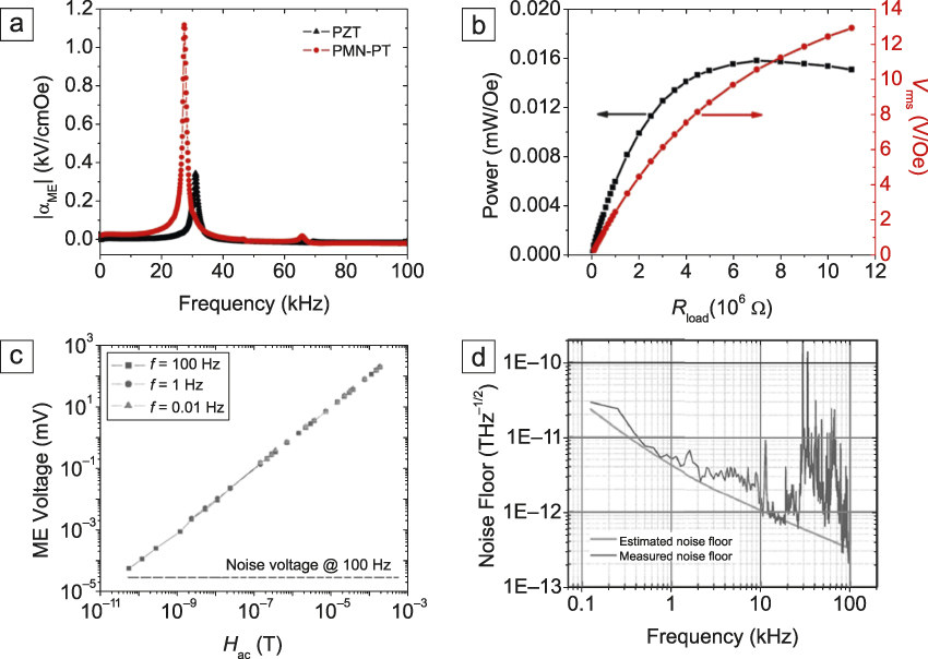
The ME effect in composite structures is mediated through an elastic interaction between the magnetostrictive and piezoelectric phases. The material is driven into excitation while two types of layers are configured in one of various operational modes, such as L–L, L–T, T–T, and c–c (where L is longitudinal, T is transverse, and c is circumferential). The ME voltage coefficient (αME) primarily depends upon the materials combination, interface quality, DC magnetic bias, and operational mode.Reference Bichurin and Viehland5,Reference Nan, Bichurin, Dong, Viehland and Srinivasan6 The highest value of αME (f = 1–103 Hz) reported to date in laminated composites is ∼20 V/cm-Oe.Reference Gao, Shen, Wang, Gray, Li and Viehland7 As first shown in 2003,Reference Dong, Cheng, Li and Viehland8 αME is dramatically enhanced by nearly 100× near the electromechanical resonance frequency, f r. At f r, laminated composites have been found to have maximum values of αME > 1000 V/cm-Oe,Reference Gao, Shen, Wang, Gray, Li and Viehland7 as illustrated in Figure 1a, which shows αME as a function of frequency for Fe-Co-Si-B (Metglas)/PZT and Metglas/Pb(Mg1/3Mb2/3)O3-xPbTiO3 (x in at.%) laminates, a thin amorphous metal alloy ribbon. This resonance gain in the ME coefficient, in addition to a correspondingly large gain in the ME charge coefficient, results in the ability of ME laminated composites to efficiently transduce magnetic to electric energies.Reference Leung, Zhuang, Xu, Srinivasan, Li and Viehland9
Summary of some of the properties of magnetoelectric (ME) laminate composites and sensors. (a) ME voltage coefficient, αME, as a function of frequency between 1 and 105 Hz for Metglas/PMN-PT (red) and Metglas/PZT (black) ME laminates. These data show the resonance enhancement of αME.Reference Gao, Shen, Wang, Gray, Li and Viehland7 (b) Power consumption as a function of load resistance (R load) for a Metglas/PZT ME sensor using an operational amplifier detection circuit.Reference Gao, Hasanyan, Shen, Wang, Li and Viehland10 The data demonstrate a power consumption of about 10–20 mW. (c) ME voltage as a function of alternating current (AC) magnetic signal (H ac), demonstrating linearity over a wide range.Reference Dong, Zhai, Xing, Li and Viehland12 Data are shown for various frequencies, where the equivalent voltage noise floor at 100 Hz is shown as a dashed line. (d) Noise spectral density for a Metglas/PMN-PT laminate sensor tested in a magnetically shielded chamber, including both laminate and detection circuit noise contributions. Both experimental and calculated data are shown.Reference Wang, Li and Viehland11 Note: PZT, Pb(ZrxTi1–x)O3; PMN-PT, Pb(Mg1/3Mb2/3)O3-xPbTiO3 (x in at.%); f, frequency; V rms, root mean square voltage.

Operation at f < f r offers a passive mode of operation that consumes little power. Power consumption of approximately 10–20 μW is typical for a ME laminated composite (see Figure 1b).Reference Gao, Hasanyan, Shen, Wang, Li and Viehland10 Noise floors are approximately 1–10 pT/Hz1/2 at f = 1 Hz.Reference Wang, Li and Viehland11 This passive mode of operation offers the potential to make battery-operated magnetic sensors for long-term deployment. Resonant operation potentially offers about a 5× reduction in the noise floor, but at increased power consumption of ∼1 mW. The voltage output from a ME laminate is a linear function of signal amplitude over eight decades of magnetic fields from 10–10 to 10–4 T,Reference Dong, Zhai, Xing, Li and Viehland12 as shown in Figure 1c. Near field levels of 10 pT, the output signal begins to approach the noise floor. The signal can still be recovered from the noise by increased averaging times, but at the cost of decreased detection responsivity.
Much effort has been focused on determining the noise floor of ME detection units (laminate and battery-operated charge amplifier circuits). It has proven difficult to attain an intrinsic noise floor below 1 pT/Hz1/2 in a passive mode. Noise models have been developed to study the intrinsic noise limits,Reference Wang, Li and Viehland11 as illustrated in Figure 1d. These studies have shown that the dielectric loss of the piezoelectric phase and the dissipation of the charge amplifier represent the limiting noise sources. Extrinsic noise floors can be reduced by use of a gradiometer (pair) of sensors, as long as the environmental noise source is coherent. In addition, other operational modes have been developed to reject particular noise sources, such as the push–pull configuration for pyroelectric contributions.Reference Bichurin and Viehland5,Reference Nan, Bichurin, Dong, Viehland and Srinivasan6
Materials development
Since the performance of composite ME sensors depends on the product of the constituent properties, the piezoelectric and magnetostrictive components are discussed in turn followed by an approach for self-organization of these components.
Piezoelectric component
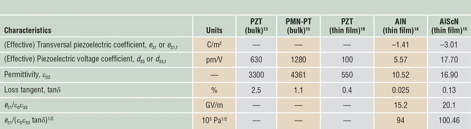
The choice of the piezoelectric material is governed by the characteristics of the ME coefficient, which favors large ratios of the piezoelectric voltage coefficient and the dielectric constant. Further criteria include loss of the piezoelectric phase described by its loss tangent (tanδ value, the achievable electrode distance, and in the case of thin-film composites, the required processing temperature. The materials of choice for the piezoelectric component are (Pb1–xZrx)TiO3 (PZT) or PMN-xPTReference Wang, Luo, Zhou, Zhao and Luo13 for bulk composites and AlN,Reference Yarar, Hrkac, Zamponi, Piorra, Kienle and Quandt14 AlScN,Reference Fichtner, Reimer, Chemnitz, Lofink and Wagner15 and PZTReference Piorra, Jahns, Teliban, Gugat, Gerken, Knöchel and Quandt16 for thin-film composites. Their main characteristics are summarized in Table I.
Typical piezoelectric properties of materials used in magnetoelectric composites.

Note: PZT, Pb(ZrxTi1–x)O3; PMN-PT, Pb(Mg1/3Mb2/3)O3-xPbTiO3 (x in at.%); ε0, dielectric constant in vacuum.
Magnetostrictive component
The requirements for the magnetostrictive component are linked to the piezomagnetic coefficient of the ferromagnetic material dλΜ/dH, which depends on the saturation magnetostriction, λΜs, and the permeability with field behavior of the piezomagnetic phase. High magnetostrictive magnetic alloys such as Terfenol-D (Tb0.7Dy0.3Fe2), FeGa, CoFe2O4, and FeCo/TbFe multilayers,Reference Quandt and Ludwig17 appear to be a natural choice for ME sensor applications. Yet, these materials display relatively low permeabilities. Hence, amorphous soft-magnetic alloys with significantly high values of positive λΜs and high permeability, such as FeGaB and FeCoSiB prepared from melt-spun ribbons or as films by sputter deposition, are mostly utilized for current sensor structures. High magnetostriction values of λΜs ≈ 70 • 10–6 together with maximum piezomagnetic coefficients of up to (dλΜ/dH)max ≈ 11 • 10–6/Oe have been achieved for state-of-the-art metallic glass alloys.Reference Lou, Insignares, Cai, Ziemer, Liu and Sun18
Laminating the materials in thin-film sensors provides another option to improve the soft magnetic characteristics. The use of magnetostrictive exchange-biased multilayers such as FeCoSiB/IrMnReference Lage, Kirchhof, Hrkac, Kienle, Jahns, Knöchel, Quandt and Meyners19 allows for the self-biasing of ME sensors and provides the preconditions for magnetic vector field sensors. The effective bias provided by the ferromagnetic-antiferromagnetic layered structures reduces the magnetic domain activity in the piezomagnetic phase. Despite decreasing the sensitivity, this reduces the magnetic sensor noise and thereby leads to an improved limit of detection as compared to unbiased ME sensors.Reference Röbisch, Yarar, Urs, Teliban, Knöchel, McCord, Quandt and Meyners20
Self-organized ME composites
ME composites can also be synthesized using a solid-state reaction (i.e., in a self-organizing manner). Spinodal decomposition separates a solid solution into phases of the same symmetry.Reference Cahn23 The spinodal decomposition reaction of a [Pb1.1(Zr0.53Ti0.47)O3]50/[NiFe2O4]50 (PZT/NFO) gelReference Ren and Wuttig21 and the templating of Pb1.1(Zr0.53Ti0.47)O3/CoFe2O4 through doping and ordering of polystyrene-block-poly(ethylene oxide) (PS-b-PEO) diblock copolymersReference Ren, Briber and Wuttig22 was shown. The 12-nm wavelength of the generated lamellate, the wave-like periodicity seen in Figure 2a, agrees with the theoretical expectation for transverse waves, which scales with the ratio of the exchange energy and the saturation magnetization of the magnetic phase.Reference Cahn24 The repulsive energy of dissimilar polymers leads to self-organized patterns when those polymers are linked.Reference Parka, Yoon and Thomas25 This phenomenon was exploited by selectively decorating the blocks of a diblock copolymer of different hydrophilicity with precursors of a ferroelectric and ferromagnetic perovskite and subsequently equilibrating the mixture. Using different ratios of the blocks, nanolamellar or nanocolumnar magnetoelectric composites (Figure 2b) could be created. In all cases, the nanostructures could be oriented via a magnetic field applied during decomposition/ordering.Reference Shenqiang, Briber and Wuttig26
(a) Magnetic force microscope image of Pb1.1[(Zr0.53Ti0.47)O3]50/[NiFe2O4]50 (PZT)(light)/(NFO)(dark) film prepared by spin-coating of a PbZrTiNiFe gel and annealing it for 12 h @ ( $T_{\rm{C}}^{{\rm{NFO}}}$–100 K) in a magnetic field, H a = 0.6 T. (b) Atomic force microscope nanodomain pattern of doped polystyrene-block-poly(ethylene oxide) (PS-b-PEO) sol-gel precursor thin film, PEO/PS = 0.35 after heating 30 min at 500°C. (c) Magnetoelectric (ME) characteristic of PZT/NFO nanocomposite film in a field of 0.6 T parallel (red) and normal (black) to the decomposition wave. The inset shows the ME coefficient as a function of the applied magnetic direct current (DC) bias field. The results demonstrate that for the inverse effect, the permeability (slope of the curves) can change by a factor of five with the application of an electrical field that even exceeds the application of a DC magnetic bias field. (d) ME characteristic of a PZT/CFO ME nanocomposite synthesized by annealing a templated PZT/CFO through doping and ordering a PS-b-PEO diblock copolymer with PEO/PS = 0.35. Note: CFO, CoFe2O4;
 $T_{\rm{C}}^{{\rm{NFO}}}$, Curie temperature of NFO; H 1, applied magnetic field in the perpendicular direction;
 ${H_\parallel }$, magnetic field parallel to the longitudinal axis; P, polarization; M, magnetization; E 1, applied electric field.

The DC ME characteristics of sample devices using the techniques previously discussed are shown in Figure 2c–d. Figure 2c displays the ME responses of spinodally decomposed PZT/NFO. The ME response coefficient is largest if the magnetic field is directed normal to the vector.Reference Kimura, Goto, Shintani, Ishizaka, Arima and Tokura27,Reference Srinivasan, Rasmussen, Gallegos and Srinivasan28 This ratio is independent of the wavelength of the lamellate, which, however, does affect the total charge that is accumulated at the electrodes. Figure 2d displays the ME characteristics of a nanocolumnar device fabricated by doped diblock copolymer templating. This configuration corresponds to a columnar (1–3) composite (where 1 = one-dimensional columns and 3 = three-dimensional matrix) that optimizes the ME interaction.Reference Ramesh29 The ME characteristics are anisotropic, as they depend on the relative direction of the fields with respect to the geometry of the nanostructure. It can be seen how an applied electric field changes the ME characteristics; the magnetization curve for H being parallel (H ǁ) to the long axis of the nanocylinders can be compared with that for H ǁ with an applied bias electric field E 1, which introduces an additional electrostrictive anisotropy field. The figure indicates a ratio of the initial permeabilities of the CFO nanocylinder array by a factor of 5 corresponding to a 500% tuning capability. At saturation, the average ME coupling coefficient equals an electric field-induced ME coefficient of 20 V/A. Its magnitude is the result of the balanced magnetic, magneto-, and electromechanical energies, the absence of epitaxial bias stresses, and the rigidity of the interface.
No sensors have been built using the self-organized devices previously described, and the dispersion of their ME characteristics has not been tested. Their potentially small size and the magneto- and electroacoustic resonances in the near terahertz range might be of interest.
Examples of ME magnetic field sensors
Bulk ME magnetic field sensors
Both passive and active magnetic sensors have been developed using bulk ME laminate structures. The passive sensor is based on charge amplifier detection and was designed to operate in the bandwidth range of 0.1 to 20 Hz.Reference Wang, Li and Viehland11,Reference Wang, Gray, Berry, Gao, Li, Li and Viehland30 Since ME sensors are also sensitive to external vibrations, an active detection method has been developed based upon modulation-demodulation.Reference Zhuang, Sing, Dolabdjian, Finkel, Li and Viehland31 In this technique, a modulation field with a carrier frequency (f c ≫ f o, where f o is the signal frequency) is applied to the sensor, shifting the magnetic signal to be close to that of the carrier. This enhances the rejection of low-frequency environmental noise, but is not a perfect solution. Improved vibration noise rejection is an important and essential aspect of future ME magnetic sensor research.
The magnetic field-level range detectable by bulk ME sensors (>1–10 pT at f = 1 Hz) is suitable for magnetic anomaly detection, geomagnetic and DC signal detection, and dipole localization. These sensors have been made into arrays and gradiometers.Reference Shen, McLaughlin, Gao, Li, Li and Viehland32 They have also been studied as electric current sensors, tunable transformers, and current–voltage (I–V) gyrator converters.Reference Nan, Bichurin, Dong, Viehland and Srinivasan6,Reference Leung, Zhuang, Xu, Srinivasan, Li and Viehland9
Thin-film ME magnetic field sensors
Thin-film ME sensors usually consist of micromachined Si cantilevers coated with piezoelectric (AlN or PZT) and magnetostrictive layers (multi- and single layers with magnetostrictive glasses), as discussed in the “Materials development” section.Reference Marauska, Jahns, Kirchhof, Claus, Quandt, Knöchel and Wagner33 They benefit from perfect mechanical coupling between the piezoelectric and magnetostrictive layers and from their mechanical resonance features. These special features include high-quality factors that can be further enhanced by vacuum sealingReference Kirchhof, Krantz, Teliban, Jahns, Marauska, Wagner, Knöchel, Gerken, Meyners and Quandt34 and the possibility to adjust the resonance frequency in the range from approximately 100 Hz to 100 kHz by the design of the cantilever. Furthermore, thin-film ME cantilever-type sensors, compared to bulk sensors, represent an important reduction in size that is essential for any spatially resolved measurement or for sensor arrays. In addition, by using thin-film magnetostrictive layers with in-plane anisotropy, it is possible to obtain magnetic field sensitivity in only one direction, which is a prerequisite for vector field measurement of magnetic fields.
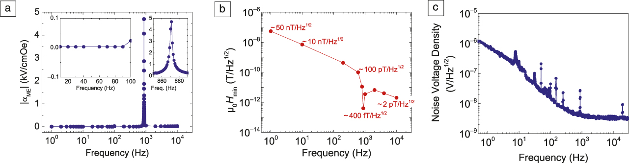
The frequency dependence of the limit of detection (LOD) is determined by the ratio of the frequency-dependent ME voltage to noise voltage density. Calculations and measurements of the noise voltage densityReference Jahns, Greve, Woltermann, Quandt and Knöchel35 have revealed three major contributing noise sources for the sensor and amplifier, namely Johnson–Nyquist noise for the sensor, as well as voltage and current noise for the amplifier, each dominant in different frequency regimes. Most importantly, typical ME thin-film sensors show a 1/f dependency in the low-frequency regime (approximately below 100 Hz) due to dominant current noise of the amplifier. Assuming a frequency-independent ME voltage outside of mechanical resonances, the LOD displays the same frequency dependence as the noise density level, except that the LOD is enhanced by the quality factor at the mechanical resonance. Detailed investigation at the mechanical resonancesReference Durdaut, Salzer, Reermann, Roebisch, Hayes, Piorra, Meyners, Quandt, Schmidt, Knoechel and Hoeft36 revealed that a further noise source has to be accounted for the thermomechanical noise of the cantilever.
Successful strategies to improve the LOD include the use of tuning fork ME cantilever-type sensors by reducing cross sensitivities to acoustics and vibrations, the deposition of the magnetostrictive layer on a smooth surface by enhancing the piezomagnetic coefficient, and an appropriate adjustment of the top electrode size by matching the regions of highest piezoelectric stresses. Using these approaches, an LOD of approximately 400 fT/Hz1/2 can be achieved in mechanical resonance, while in the low-frequency regime (<100 Hz) the LOD is in the nT/Hz1/2 range and suffering from the higher 1/f noise and the lower signal level (typically proportional to the quality factor of the resonator)Reference Yarar, Salzer, Hrkac, Piorra, Höft, Knöchel, Kienle and Quandt37 (Figure 3).
(a) Magnetoelectric (ME) coefficient (αME) (the insets show the values [left] outside of resonance and [right] a magnified view of the resonance), (b) limit of detection (LOD), and (c) noise voltage density, all as a function of frequency, of a cantilever-type thin-film ME sensor composed of AlN and FeCoSiB layers. The obtained frequency-dependent LOD in (b) can be derived from the ratio of the noise density level in (c) to the size of the ME effect in (a). Thus, the LOD minimum corresponds to the effect enhancement by the mechanical resonance. Note: μ0, permeability in vacuum; H min, minimum detectable magnetic field.Reference Yarar, Salzer, Hrkac, Piorra, Höft, Knöchel, Kienle and Quandt37

Operation of ME magnetic field sensors
Magnetic and electric frequency conversion
Overcoming the previously mentioned limitations at low frequencies for ME magnetic field sensors is possible by applying magnetic or electric frequency conversion (MFC or EFC)Reference Jahns, Zabel, Marauska, Gojdka, Wagner, Knöchel, Adelung and Faupel38,Reference Hayes, Salzer, Reermann, Yarar, Röbisch, Piorra, Meyners, Höft, Knöchel, Schmidt and Quandt39 techniques that allow transferring an arbitrary frequency outside resonance to the mechanical resonance frequency of the sensor. In the case of MFC, the nonlinear characteristics of the magnetostriction curve are utilized, which changes almost quadratically with the magnetic field in a certain range around zero field. If an alternating bias is applied instead of the common constant bias field, the superposition of this alternating bias and the measurement field contains a product term, which expresses a frequency conversion. If the modulation frequency is adjusted such that the sum of the modulation frequency and the signal frequency exactly equal the mechanical resonance of the sensor, this frequency conversion can offer the possibility for resonant operation of the sensor at a virtually arbitrary signal frequency.
In the case of the EFC, a piezoelectric-induced periodic actuation of the sensor is used, whereby inverse magnetostriction results in periodic change of the magnetic state of the magnetostrictive component. Correspondingly, it leads to a similar frequency conversion by superposition with the measurement field. These approaches lead to an improvement of the LOD by many orders of magnitude compared to the direct detection mode and to a decreased sensitivity to vibrational distortions at low frequencies. As these distortions do not significantly influence the magnetostrictive component, they are not up-converted to the mechanical resonance.
Delta-E effect sensor
ME sensors based on the delta-E effect, magnetic field-induced changes of the elastic properties, require a different way of operation. The delta-E effectReference Berry and Pritchet40 manifests itself in a coupling of strain and magnetostriction, which results in a magnetoelastically induced change of the direction of magnetization in unsaturated magnetic materials. The addition of a magnetostrictive strain to the elastic strain leads to an apparent reduction of the elastic moduli, the magnetic field dependency of which is utilized for magnetic field sensing.
Current modes of operations are based on detecting the magnetic field-induced resonant detuning in electromechanical bulkReference Nan, Hui, Rinaldi and Sun41 and cantilever-based resonators.Reference Jahns, Zabel, Marauska, Gojdka, Wagner, Knöchel, Adelung and Faupel38 The electrical readout as well as the mechanical excitation are achieved through a piezoelectric layer. The points of operation are defined by the mechanical resonance frequency, f r, of the system and the magnetic working point, which is chosen near the maximum of variation of the electromechanical resonance frequency versus the magnetic field, dfrdH. A magnetic field then transfers into a frequency shift of the resonance. By simultaneously operating and detecting several mechanical modes,Reference Zabel, Reermann, Fichtner, Kirchhof, Quandt, Wagner, Schmidt and Faupel42 the sensitivity of the delta-E effect sensors can be enhanced. An alternative approach is based on the magnetic field variance of the propagational phase shift of acoustic surface shear waves in a delay line sensor arrangement.Reference Kittmann, Durdaut, Zabel, Reermann, Schmalz, Spetzler, Meyners, Sun, McCord, Gerken, Schmidt, Höft, Knöchel, Faupel and Quandt43 In general, delta-E effect sensors possess high bandwidth sensor characteristics, suitable for the detection of heart and brain signals.
Comparison with state-of-the-art magnetic field sensors
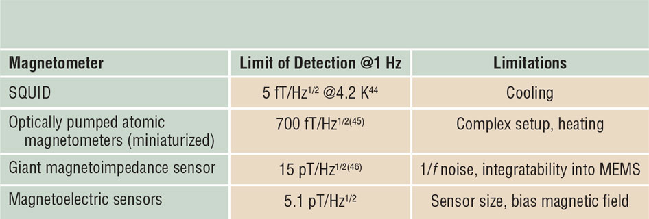
This comparison focuses only on those magnetometers that are currently the most relevant for applications that require spatial resolution, a low limit of detection (pT-range or lower) in the low-frequency range (<1 kHz) (e.g., for biomagnetic measurements). Table II summarizes currently available sensors with the detection limit for a 1 Hz magnetic signal and addresses their limitations for biomagnetic measurements.
Currently available magnetic field sensors with the obtained limit of detection for a 1 Hz magnetic signal.

These sensors can be used for biomagnetic measurements. Note: SQUID, superconducting quantum interference device; MEMS, microelectromechanical systems; f, frequency.
The gold standard for biomagnetic measurements is superconducting quantum interference device sensors with a LOD of a few fT/Hz1/2 at 1 Hz, operated at liquid helium temperatureReference Schmelz, Stolz, Zakosarenko, Schönau, Anders, Fritzsch, Mück, Meyer and Meyer44 and work as a reference for any room-temperature magnetic field sensor approach. Two room-temperature magnetic field sensors have been successfully used for biomagnetic measurements: (1) optically pumped atomic magnetometers,Reference Sander, Preusser, Mhaskar, Kitching, Trahms and Knappe45 which are still rather complex, require heating, and use the Zeeman splitting of electronic levels to monitor the precession frequency of protons or electrons and (2) giant magnetoimpedance magnetometers,Reference Portalier, Dufay, Saez and Dolabdjian46 which present a 1/f behavior at low frequencies with a white noise of 15 pT/Hz1/2 at 1 Hz. In comparison, the achieved noise level of 5.1 pT/Hz1/2 at 1 Hz for the best magnetoelectric sensorReference Wang, Gray, Berry, Gao, Li, Li and Viehland30 is promising for future applications for the detection of biomagnetic signals in unshielded environments.
Conclusions
ME composites are attractive as magnetic field sensors for small magnetic fields at low frequencies. In a direct readout, they offer passive operation, a linear response over six orders of magnitude, and a low limit of detection in the low pT/Hz1/2 range. The performance can even be enhanced by using frequency-conversion approaches or by employing the delta-E effect. Using these sensors for the measurement of biomagnetic signals is a promising next step.
Acknowledgments
D.V. acknowledges support from the Office of Naval Research (N000141512457). E.Q. and J.M.C. acknowledge the support of the Collaborative Research Center CRC 1261 “Magnetoelectric Sensors: From Composite Materials to Biomagnetic Diagnostics,” funded by the Deutsche Forschungsgemeinschaft (DFG).

Dwight Viehland is the Jack E. Cowling Professor of Engineering in the Department of Materials Science and Engineering at Virginia Tech. He obtained his PhD degree in solid-state science at The Pennsylvania State University. His research interests include electrical, magnetic, and structural properties of oxides. He has published extensively on magnetoelectric materials, phase transformations, domain structures in ferroelectrics, and epitaxial deposition of all oxide heterostructures. He has published more than 500 papers, which have received approximately 25,000 citations. He is a Fellow of The American Ceramic Society, and was an ONR Young Investigator. Viehland can be reached by email at dviehlan@vt.edu.

Manfred R.G. Wuttig is a professor of materials science at the University of Maryland. He received his diploma in physics in 1956 and doctorate in physical metallurgy in 1962 from the Technical University of Berlin, Germany, and subsequently moved to the University of Illinois at Urbana-Champaign. From 1963 to 1984, he was a professor at the University of Missouri at Rolla. After serving briefly at the National Science Foundation, he attended the University of Maryland in 1986. His research focused initially on defects in solids, and, later, on phase transformations and multiferroics. Wuttig can be reached by email at wuttig@umd.edu.

Jeffrey McCord is a Heisenberg professor for nanoscale magnetic materials and magnetic domains at the Institute for Materials Science, Kiel University, Germany. He received his PhD degree in materials science in 1997 from the University of Erlangen-Nürnberg, Germany. In 1997, he joined the IBM Storage Division. From 2002 to 2009, he was a research scientist at IFW Dresden, Germany, and was department head at HZDR Dresden, Germany, until 2011. He is a co-founder of Evico Magnetics GmbH. His research focuses on magnetic domain effects in magnetic thin films. McCord can be reached by email at jmc@tf.uni-kiel.de.

Eckhard Quandt holds the Chair for Inorganic Functional Materials at Kiel University, Germany. He studied physics in Kiel and Berlin, where he received his diploma and doctorate in 1986 and 1990. Since 1991, he has been working on smart materials, first in Karlsruhe, then in Bonn, and since 2006, at Kiel University. From 2014 to 2016, he was the dean of the faculty of engineering at Kiel University. He is currently a member of the Deutsche Forschungsgemeinschaft review board “Materials Science” and of the German National Academy of Science and Engineering. Quandt can be reached by email at eq@tf.uni-kiel.de.