1 Introduction
Invariant solutions of the Navier–Stokes equations are known to play an important role in the dynamics of turbulence at low Reynolds numbers (Kawahara, Uhlmann & van Veen Reference Kawahara, Uhlmann and van Veen2012). Invariant solutions in the form of equilibria, travelling waves and periodic orbits have been computed precisely for canonical shear flows such as pipe flow (Faisst & Eckhardt Reference Faisst and Eckhardt2003; Wedin & Kerswell Reference Wedin and Kerswell2004; Duguet, Pringle & Kerswell Reference Duguet, Pringle and Kerswell2008), plane Couette flow (Nagata Reference Nagata1990; Kawahara & Kida Reference Kawahara and Kida2001; Viswanath Reference Viswanath2007; Gibson, Halcrow & Cvitanović Reference Gibson, Halcrow and Cvitanović2009) and plane Poiseuille flow (Waleffe Reference Waleffe2001; Gibson & Brand Reference Gibson and Brand2014). The development of the invariant-solutions approach to turbulence has largely occurred in the simplified context of small, periodic domains or ‘minimal flow units’ (Jiménez & Moin Reference Jiménez and Moin1991). More recently, invariant solutions with localized support have been computed for flows on spatially extended domains. These include spanwise-localized equilibria and travelling waves of plane Couette flow (Schneider, Gibson & Burke Reference Schneider, Gibson and Burke2010a ; Schneider, Marinc & Eckhardt Reference Schneider, Marinc and Eckhardt2010b ; Deguchi, Hall & Walton Reference Deguchi, Hall and Walton2013; Gibson & Brand Reference Gibson and Brand2014), and spanwise-localized travelling waves (Gibson & Brand Reference Gibson and Brand2014) and a periodic orbit (Zammert & Eckhardt Reference Zammert and Eckhardt2014a ) of plane Poiseuille flow. Avila et al. (Reference Avila, Mellibovsky, Roland and Hof2013) computed a streamwise-localized periodic orbit of pipe flow, Mellibovsky & Meseguer (Reference Mellibovsky and Meseguer2015) a streamwise-localized periodic orbit of plane Poiseuille flow, Brand & Gibson (Reference Brand and Gibson2014) a doubly localized equilibrium solution of plane Couette flow and Zammert & Eckhardt (Reference Zammert and Eckhardt2014b ) a doubly localized periodic orbit of plane Poiseuille flow. The existence and structure of these spatially localized solutions suggests that they are relevant to large-scale patterns of laminar–turbulent intermittency, such as turbulent stripes, spots and puffs. For example, the periodic orbit of Avila et al. (Reference Avila, Mellibovsky, Roland and Hof2013) shares the spatial structure and complexity of turbulent puffs in pipe flow, and its bifurcation sequence provides a compelling explanation of the development of transient turbulence in pipes. The doubly localized equilibrium of Brand & Gibson (Reference Brand and Gibson2014) has the characteristic shape and structure of turbulent spots in low-Reynolds-number plane Couette flow, and for a range of Reynolds numbers sits on the boundary between laminar flow and turbulence. Analysis of these localized solutions has so far focused on their bifurcations from spatially periodic solutions (Chantry, Willis & Kerswell Reference Chantry, Willis and Kerswell2014; Mellibovsky & Meseguer Reference Mellibovsky and Meseguer2015) and linear analysis of their decaying tails (Brand & Gibson Reference Brand and Gibson2014; Gibson & Brand Reference Gibson and Brand2014).
The spanwise-localized invariant solutions of plane Couette flow of Schneider et al. (Reference Schneider, Marinc and Eckhardt2010b ), are notable for being the first localized solutions discovered, for their relation to the widely studied equilibrium solution of Nagata (Reference Nagata1990), Clever & Busse (Reference Clever and Busse1997) and Waleffe (Reference Waleffe1998) (hereafter NBCW), and for exhibiting the particularly interesting feature of homoclinic snaking. Homoclinic snaking is a process by which localized solutions grow additional structure at their fronts in a sequence of saddle-node bifurcations when continued parametrically (Woods & Champneys Reference Woods and Champneys1999, Burke & Knobloch Reference Burke and Knobloch2006, Reference Burke and Knobloch2007a , Schneider et al. Reference Schneider, Gibson and Burke2010a ; see also § 3.1). Homoclinic snaking occurs in a number of pattern-forming systems with localized solutions, including binary fluid convection (Batiste & Knobloch Reference Batiste and Knobloch2005) and magneto-convection (Batiste et al. Reference Batiste, Knobloch, Alonso and Mercader2006), and it is well-understood mathematically for the one-dimensional Swift–Hohenberg equation (Burke & Knobloch Reference Burke and Knobloch2006, Reference Burke and Knobloch2007a ; Beck et al. Reference Beck, Knobloch, Lloyd, Sandstede and Wagenknecht2009). Knobloch (Reference Knobloch2015) provides a comprehensive review of localization and homoclinic snaking in dissipative systems. Though no explicit connection between the Swift–Hohenberg and the Navier–Stokes equations is known, the striking similarity of the localized plane Couette solutions and the localized solutions of Swift–Hohenberg with cubic–quintic nonlinearity suggests there might be a mathematical connection between the two systems. These similarities include the structure of localization, the snaking behaviour, the even/odd symmetry of the snaking solutions and the existence of asymmetric rung solutions (Schneider et al. Reference Schneider, Gibson and Burke2010a ). One might envision, for example, that a reduced-order model of the localized solutions (Hall & Sherwin Reference Hall and Sherwin2010; Hall Reference Hall2012; Beaume et al. Reference Beaume, Chini, Julien and Knobloch2015) might relate the spanwise variation of their mean streamwise flow to the cubic–quintic Swift–Hohenberg equation. Such a relation would link the mathematically well-developed field of pattern-formation theory to the localized solutions of shear flows cited above, or to recent numerical studies of laminar–turbulent pattern formation in extended shear flows (Barkley & Tuckerman Reference Barkley and Tuckerman2005; Duguet, Schlatter & Henningson Reference Duguet, Schlatter and Henningson2010; Tuckerman et al. Reference Tuckerman, Kreilos, Schrobsdorff, Schneider and Gibson2014).
In support of developing such connections between pattern-formation theory and shear flows, we present in this paper a more detailed analysis of the snaking solutions of Schneider et al. (Reference Schneider, Gibson and Burke2010a
,Reference Schneider, Marinc and Eckhardt
b
). In particular, we examine the effects of varying the streamwise wavelength
 $L_{x}$
of the solutions compared with the fixed
 $L_{x}=4{\rm\pi}$
of Schneider et al. (Reference Schneider, Gibson and Burke2010a
). We find that homoclinic snaking is robust in
 $L_{x}$
and that the snaking region moves upwards in Reynolds number with decreasing
 $L_{x}$
. The ranges of streamwise wavelength and Reynolds number in which snaking solutions exist is found to be
 $1.7{\rm\pi}\leqslant L_{x}\leqslant 4.2{\rm\pi}$
and
 $165\leqslant \mathit{Re}\leqslant 2700$
. In addition, we find several interesting solution properties that are suppressed at the parameters studied in Schneider et al. (Reference Schneider, Gibson and Burke2010a
). As
 $L_{x}$
decreases below
 $4{\rm\pi}$
and
 $\mathit{Re}$
increases above
 $165$
, the localized solutions deform appreciably compared with their strictly periodic counterparts, the localized equilibria exhibiting a linear skewing and the travelling waves a quadratic bending. We show that skewing and bending are related to the respective symmetries of the equilibrium and travelling wave solutions, and that bending induces finite-size effects in the travelling waves that scale as the inverse of their spanwise width. In contrast, skewing induces no such finite-size effects on the equilibrium solution. We show that the skewed solutions lead to a new periodically winding form of the NBCW equilibrium solution of plane Couette flow.
The structure of this paper is as follows. Section 2 outlines the problem formulation and numerical methods. Section 3 describes the features of the localized solutions at fixed streamwise wavelength
 $L_{x}$
, including homoclinic snaking, bending, skewing and finite-size effects. Section 4 discusses the effects of varying streamwise wavelength, including the regions of wavelength and Reynolds number over which snaking occurs, the breakdown of snaking outside these regions, and the stability of the solutions. Section 5 discusses the periodic pattern in the interior of the localized solutions and its relation to the NBCW solution. The new winding solution is presented in § 5.
2 Problem formulation, methodology and conventions
Plane Couette flow consists of an incompressible Newtonian fluid between two infinite parallel plates moving at constant relative velocity. The Reynolds number is given by
 $\mathit{Re}=Uh/{\it\nu}$
where
 $U$
is half the relative wall speed,
 $h$
is half the distance between the walls and
 ${\it\nu}$
is the kinematic viscosity. The
 $\boldsymbol{x}=(x,y,z)$
coordinates are aligned with the streamwise, wall-normal and spanwise directions, where streamwise is defined as the direction of relative wall motion. After non-dimensionalization, the walls at
 $y=\pm 1$
move at speeds
 $\pm 1$
in the
 $x$
direction, and the laminar velocity field is given by
 $y\boldsymbol{e}_{x}$
. We decompose the total fluid velocity into a sum of the laminar flow and the deviation from laminar:
 $\boldsymbol{u}_{tot}=y\boldsymbol{e}_{x}+\boldsymbol{u}$
. Hereafter we refer to the deviation field
 $\boldsymbol{u}(\boldsymbol{x},t)=[u,v,w](x,y,z,t)$
as ‘velocity.’ In these terms the laminar solution is specified by
 $\boldsymbol{u}=0$
,
 $p=0$
and the Navier–Stokes equations take the form
 $$\begin{eqnarray}\displaystyle \frac{\partial \boldsymbol{u}}{\partial t}+y\frac{\partial \boldsymbol{u}}{\partial x}+v\boldsymbol{e}_{x}+\boldsymbol{u}\boldsymbol{\cdot }\boldsymbol{{\rm\nabla}}\boldsymbol{u}=-\boldsymbol{{\rm\nabla}}p+\frac{1}{\mathit{Re}}{\rm\nabla}^{2}\boldsymbol{u},\quad \boldsymbol{{\rm\nabla}}\boldsymbol{\cdot }\boldsymbol{u}=0. & & \displaystyle\end{eqnarray}$$
The computational domain
 ${\it\Omega}=[-L_{x}/2,L_{x}/2]\times [-1,1]\times [-L_{z}/2,L_{z}/2]$
has periodic boundary conditions in
 $x$
and
 $z$
and no-slip conditions at the walls. For spanwise-localized solutions,
 $L_{z}$
is set to be large so that
 ${\it\Omega}$
approximates a spanwise-infinite domain. We use
 $\hat{L}_{z}$
to denote the spanwise wavelength of nearly periodic, small-wavelength patterns within the spanwise-localized solutions; typically
 $\hat{L}_{z}\ll L_{z}$
. In the present work we impose zero mean pressure gradient in all computations, leaving the mean (bulk) flow to vary dynamically. As described in Gibson, Halcrow & Cvitanović (Reference Gibson, Halcrow and Cvitanović2008) and Gibson et al. (Reference Gibson, Halcrow and Cvitanović2009), direct numerical simulations are performed with Fourier–Chebyshev spatial discretization with
 $2/3$
-style dealiasing and semi-implicit time-stepping. Travelling-wave and equilibrium solutions of (2.1) are computed with a Newton–Krylov hookstep algorithm. Spatial discretizations are chosen so that truncated Fourier coefficients are
 $O(10^{-5})$
at most and truncated Chebyshev coefficients are
 $O(10^{-9})$
. The computational domain length
 $L_{z}$
is chosen so that the magnitude of velocity is no more than
 $10^{-3}$
at
 $z=\pm L_{z}/2$
. The adequacy of spatial resolution was tested by recomputing solutions at higher resolution. Most of the results discussed in § 3, for example, were computed with
 $24\times 33\times 512$
gridpoints on a
 $3{\rm\pi}\times 2\times 24{\rm\pi}$
domain, for Reynolds numbers in the range
 $200\leqslant \mathit{Re}\leqslant 350$
. All software and solution data are available for download at http://www.channelflow.org.
The equilibrium and travelling-wave solutions discussed here are all steady states (in a fixed or travelling frame of reference, respectively), so the energy dissipation rate balances the power input from wall shear instantaneously:
 $$\begin{eqnarray}\displaystyle D=I=\frac{1}{2L_{x}}\int _{-L_{x}/2}^{L_{x}/2}\int _{-L_{z}/2}^{L_{z}/2}\left(\left.\frac{\partial u}{\partial y}\right|_{y=-1}+\left.\frac{\partial u}{\partial y}\right|_{y=1}\right)\,\text{d}x\,\text{d}z. & & \displaystyle\end{eqnarray}$$
Note that
 $D$
is defined in terms of the deviation velocity
 $\boldsymbol{u}$
and not the total velocity
 $\boldsymbol{u}_{tot}$
, so that
 $D$
measures the excess energy dissipation of spanwise-localized solutions over the laminar flow, which has
 $D=0$
. Since the internal structure of a spanwise-localized solutions stays roughly constant as non-laminar structure grows at its fronts,
 $D$
serves as a good measure of the spanwise width of a solution. The lack of
 $L_{z}$
normalization makes the
 $D$
of a spanwise-localized solution insensitive to the choice of spanwise length for the computational domain in which it is embedded.
For discussing the symmetries of the flow we follow the conventions of Gibson & Brand (Reference Gibson and Brand2014), here adding the action of symmetries on the pressure field. Let
 $$\begin{eqnarray}\displaystyle \left.\begin{array}{@{}c@{}}{\it\sigma}_{x}:[u,v,w,p](x,y,z)\rightarrow [-u,v,w,p](-x,y,z),\\ {\it\sigma}_{y}:[u,v,w,p](x,y,z)\rightarrow [u,-v,w,p](x,-y,z),\\ {\it\sigma}_{z}:[u,v,w,p](x,y,z)\rightarrow [u,v,-w,p](x,y,-z),\\ {\it\tau}({\rm\Delta}x,{\rm\Delta}z):[u,v,w,p](x,y,z)\rightarrow [u,v,w,p](x+{\rm\Delta}x,y,z+{\rm\Delta}z),\end{array}\right\} & & \displaystyle\end{eqnarray}$$
and let concatenation of subscripts indicate products, e.g.
 ${\it\sigma}_{xy}={\it\sigma}_{x}{\it\sigma}_{y}$
. For
 $(\ell _{x},\ell _{z})$
-periodic fields we define two half-wavelength translation operators
 ${\it\tau}_{x}={\it\tau}(\ell _{x}/2,0)$
and
 ${\it\tau}_{z}={\it\tau}(0,\ell _{z}/2)$
. The standard group-theoretic angle-bracket notation indicates the group formed by a set of generators; for example
 $\langle {\it\sigma}_{xy},{\it\tau}_{x}{\it\sigma}_{z}\rangle =\{e,{\it\sigma}_{xy},{\it\tau}_{x}{\it\sigma}_{z},{\it\tau}_{x}{\it\sigma}_{xyz}\}$
, where
 $e$
is the identity (Dummit & Foote Reference Dummit and Foote2004).
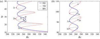
Homoclinic snaking of localized solutions at
 $L_{x}=3{\rm\pi}$
. (a) Snaking curves at low
 $D$
(small spanwise width) for localized equilibrium (EQ), travelling-wave (TW) and rung (RN) solutions. Labels indicate the solutions shown as velocity fields in figure 2. (b) Snaking curves at high
 $D$
(large spanwise width). Filled circles indicate the points of zero skewing (for equilibria) and zero bending (for travelling waves) along the snaking curves; signed open circles mark the positions and signs of the maxima in magnitude of skewing and bending (see § 3.3). Pressure fields for the labelled points are shown in figure 3. Both subplots are details of the
 $L_{x}=3{\rm\pi}$
snaking curve shown in figure 4(d).

3 Solution properties at fixed streamwise wavelength
3.1 Snaking
The primary notable feature of the localized solutions is their homoclinic snaking. Under continuation in Reynolds number at fixed streamwise wavenumber, the localized equilibrium and travelling-wave solutions follow curves that snake upwards in the
 $\mathit{Re},D$
plane, as shown in detail in figure 1 and over a larger range of
 $D$
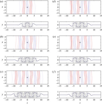
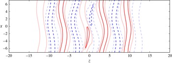
in figure 4(d). Velocity fields corresponding to the labelled points in figure 1(a) are shown in figure 2. Figure 2(a–c) shows that the travelling-wave solution grows additional structure at the solution fronts as it moves upwards in
 $D$
along the snaking curve, while the interior structure remains nearly constant. The structure of the fronts is the same at alternating saddle-node points (a,c), while the saddle-node point (b) between them has front structure of opposite streamwise sign. Note that due to the
 ${\it\sigma}_{xy}$
symmetry of plane Couette flow, every travelling-wave solution
 $\boldsymbol{u}$
with wave speed
 $c_{x}$
has a symmetric partner
 ${\it\sigma}_{xy}\boldsymbol{u}$
with wave speed
 $-c_{x}$
. The
 ${\it\sigma}_{xy}\boldsymbol{u}$
symmetric partner of figure 2(b) has fronts with the same structure and streamwise sign as figure 2(a,c).
Figure 1(a) also shows ‘rung’ solutions that bifurcate from the equilibrium solution in a pitchfork bifurcation near the saddle-node bifurcation points of the equilibrium and connect to the travelling wave near their saddle-node points (or vice versa). The rung solutions are asymmetric, as if formed from an amplitude envelope that drifts in the spanwise direction as the solution grows away from its pitchfork bifurcation point (see Kao, Beaume & Knobloch Reference Kao, Beaume and Knobloch2014, figure 6). The rung solutions can also be understood as a combination of two solutions near the saddle-node bifurcation point, with the same Reynolds number and the same internal structure, but with different spanwise widths
 $D$
. For example, the equilibria marked 2d and 2f in figure 1(a) and depicted as streamwise velocity fields in figure 2(d,f) are indistinguishable within the interior
 $-5<z<5$
. But their differing values of
 $D$
indicate different spanwise widths. The contour lines of the fronts of 2(f) extend towards
 $|z|\approx 9$
, whereas those of 2(d) reach just
 $|z|\approx 7$
. The rung solution shown as figure 2(e) and marked 2
e in figure 1(a) can then be understood as splicing together the left half of figure 2(d) and the right half of figure 2(f). This splicing can be done over a range of
 $\mathit{Re}$
in the interior of the saddle-node bifurcation, i.e. along the black lines of the rung branches shown figure 1(a). The splicing construction is necessarily inexact, since the rung solutions have no symmetries and hence travel in both
 $x$
and
 $z$
, compared with the equilibrium, which is fixed. However, it is close enough that such spliced equilibria converge quickly to the rung solutions under Newton–Krylov hookstep search. The rung solutions in this paper were computed by splicing and refinement, followed by continuation in Reynolds number.
Velocity fields of localized solutions illustrated by contours of streamwise velocity in the
 $y=0$
midplane,
 $u(x,0,z)$
and arrow plots of the streamwise-averaged cross-stream velocity,
 $[\bar{v},\bar{w}](y,z)$
. Eight contour levels are evenly spaced between
 $\pm 0.9$
, with negative
 $u$
in dashed blue lines and positive in solid red. Contour lines for
 $\bar{u}=0$
are superimposed on the arrow plots. (a–c) The travelling-wave (TW) solution at the three successive lower saddle-node bifurcation points marked on the snaking curve in figure 1(a). (d,f) The equilibrium (EQ) solution at
 $\mathit{Re}=260$
above and below an upper saddle-node bifurcation, and (e) the rung (RN) solution at
 $\mathit{Re}=260$
, at points labelled in figure 1(a). The solution is shown for
 $L_{x}=3{\rm\pi}$
and on a subset of the
 $L_{z}=16{\rm\pi}$
computational domain.

3.2 Symmetries of localized solutions
The differences between travelling waves, equilibria and rungs are intimately related to the different symmetries of those solutions, which can be understood in terms of symmetry-breaking bifurcations of the more symmetric, spatially periodic NBCW solution. This is discussed in detail in Gibson & Brand (Reference Gibson and Brand2014); here we present a brief summary. With proper placement of the
 $z$
origin, the travelling waves have a
 ${\it\tau}_{x}{\it\sigma}_{z}$
‘shift–reflect’ symmetry. That is, a travelling-wave solution satisfies
 $\boldsymbol{u}={\it\tau}_{x}{\it\sigma}_{z}\boldsymbol{u}$
or
 $$\begin{eqnarray}\displaystyle [u,v,w,p](x,y,z)=[u,v,-w,p](x+\ell _{x}/2,y,-z). & & \displaystyle\end{eqnarray}$$
Solutions with this symmetry can travel in
 $x$
but not
 $z$
, since the inversion in
 $z$
about the origin locks the
 $z$
phase of the solution, but no such restriction exists for
 $x$
. For similar reasons, the travelling waves can have non-zero mean streamwise velocity, but their mean spanwise velocity must be zero. The
 ${\it\tau}_{x}{\it\sigma}_{z}$
symmetry of the localized travelling waves arises from a subharmonic-in-
 $z$
bifurcation of the
 $(\ell _{x},\ell _{z})$
-periodic NBCW solution, which has symmetries
 $\langle {\it\tau}_{x}{\it\sigma}_{z},{\it\tau}_{xz}{\it\sigma}_{xy}\rangle$
when taken in the spatial phase of Waleffe (Reference Waleffe2003), The subharmonic-in-
 $z$
bifurcation necessarily breaks the
 ${\it\tau}_{xz}{\it\sigma}_{xy}$
symmetry, since this symmetry implies
 $\ell _{z}$
periodicity, as follows. If
 ${\it\tau}_{xz}{\it\sigma}_{xy}\boldsymbol{u}=\boldsymbol{u}$
, then
 $({\it\tau}_{xz}{\it\sigma}_{xy})^{2}\boldsymbol{u}=\boldsymbol{u}$
. But a brief calculation shows that
 $({\it\tau}_{xz}{\it\sigma}_{xy})^{2}={\it\tau}(0,\ell _{z})$
. Thus, the bifurcated solution loses the
 ${\it\tau}_{xz}{\it\sigma}_{xy}$
symmetry of NBCW and retains only
 ${\it\tau}_{x}{\it\sigma}_{z}$
.
The localized equilibrium solution has
 ${\it\sigma}_{xyz}$
inversion symmetry, satisfying
 $$\begin{eqnarray}\displaystyle [u,v,w,p](x,y,z)=[-u,-v,-w,p](-x,-y,-z). & & \displaystyle\end{eqnarray}$$
As a result of the inversion of all velocity components about the origin, the spanwise-localized solutions with this symmetry are prevented from travelling in
 $x$
or
 $z$
, and the spatial average of all velocity components is zero. The
 ${\it\sigma}_{xyz}$
symmetry of the localized equilibrium arises from a similar bifurcation of a phase-shifted NBCW solution. Shifting the NBCW solution by a quarter-wavelength in
 $z$
,
 $\boldsymbol{u}\rightarrow {\it\tau}_{z}^{1/2}\boldsymbol{u}$
, changes each of its symmetries
 $s$
to the conjugate symmetry
 ${\it\tau}_{z}^{-1/2}s{\it\tau}_{z}^{1/2}$
(Gibson et al.
Reference Gibson, Halcrow and Cvitanović2009). A brief calculation shows that the conjugated symmetry group of the phase-shifted NBCW solution is
 $\langle {\it\tau}_{xz}{\it\sigma}_{xy},{\it\sigma}_{xyz}\rangle$
. The
 ${\it\tau}_{xz}{\it\sigma}_{xy}$
symmetry implies
 $\ell _{z}$
-periodicity, as before, so the subharmonic-in-
 $z$
bifurcation breaks the
 ${\it\tau}_{xz}{\it\sigma}_{xy}$
symmetry but retains
 ${\it\sigma}_{xyz}$
.
The symmetries of the travelling-wave and equilibrium solutions and the lack of symmetry in rung solutions are evident in the velocity-field plots shown in figure 2. The
 $z$
-mirror,
 $x$
-shift
 ${\it\tau}_{x}{\it\sigma}_{z}$
travelling-wave symmetry (3.1) is particularly apparent in the fronts of the midplane
 $u$
contour plots of figure 2(a–c), and an even
 $z$
-mirror symmetry is apparent in the corresponding
 $x$
-averaged cross-stream
 $[\bar{v},\bar{w}](y,z)$
plots. It is also evident from these plots why the travelling-wave solution travels in
 $x$
. In each of figure 2(a–c), both the
 $u(x,0,z)$
plots and the
 $[\bar{v},\bar{w}](y,z)$
plots show a clear imbalance between the positive/negative streamwise streaks. In comparison, for the equilibrium solutions, the
 ${\it\sigma}_{xyz}$
symmetry of the equilibrium matches each streamwise streak at negative
 $z$
with an equal streak at positive
 $z$
of opposite sign. The rung solution figure 2(e), in contrast, has no symmetry at all. The lack of symmetry in the rungs is due fundamentally to their symmetry-breaking bifurcations from the travelling-wave and equilibrium solutions. It can also be understood physically as a consequence of the formation of rungs via splicing as described in § 3.1, which clearly breaks the
 ${\it\sigma}_{xyz}$
symmetry of the equilibrium solution (or the
 ${\it\tau}_{x}{\it\sigma}_{z}$
symmetry if constructed by splicing travelling waves). The complete lack of symmetry in rung solutions means they generally have non-zero wave speeds and non-zero net velocity in both the streamwise and spanwise directions.
3.3 Bending, skewing and finite-size effects
The equilibrium (EQ), travelling-wave (TW) and rung solutions (RN) shown as velocity fields in figure 2 are at low
 $D$
and thus have small spanwise width. The three different types of solutions appear at first glance to consist of a few copies of the same spanwise-periodic structure placed side-by-side, with fronts on either side that taper to laminar flow. This description, however, is neither entirely accurate nor complete. First of all, the interior structure of the three types of solutions must differ at least slightly because the solution types move at different wave speeds (
 $c_{x}=c_{z}=0$
for equilibria,
 $c_{x}\neq 0,c_{z}=0$
for travelling waves and
 $c_{x}\neq 0,c_{z}\neq 0$
for the rungs). But further differences between the three solutions types become apparent at higher
 $D$
and greater spanwise width. In this subsection we show that:
-
(i) the EQs skew, displaying a linear tilt in
 $x$
against
$z$
(figure 3
a);
-
(ii) the TWs bend, displaying a quadratic curvature in
$x$
against
$z$
(figure 3
b); -
(iii) the EQ snaking region has constant bounds in
$\mathit{Re}$
(figure 4
d); -
(iv) the TW snaking region is wider but converges to the EQ’s as
$D^{-1}$
(figure 4
d); -
(v) the TW’s streamwise wave speed decreases to zero as
$D^{-1}$
, (figure 4
c); -
(vi) the EQ’s interior structure is periodic and winds in
$x,z$
(figure 3
a); and -
(vii) the TW’s interior structure is non-periodic and slowly modulated in
$z$
(figure 3
b).


The common thread among these phenomena is the interplay between the fronts and the interior structure. Much of the above can be understood by assuming that the fronts are the determining structures of the solutions, and viewing the other properties as a consequences of the fronts and their orientations, as determined by the solution symmetries.
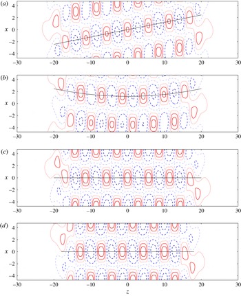
Bending and skewing. Contour plots of pressure
 $p(x,0,z)$
in the
 $y=0$
midplane are shown for localized equilibrium (EQ) and travelling-wave (TW) solutions with maximum and zero skewing and bending, corresponding to points marked on figure 1(b). (a) EQ at maximum skewing, (b) TW at maximum bending, (c) EQ at zero skewing, and (d) TW at zero bending. Eight contour levels are evenly spaced between
 $p=\pm 0.025$
, dashed blue for negative
 $p$
and solid red for positive. The solution is shown for
 $L_{x}=3{\rm\pi}$
and on a subset of the
 $L_{z}=16{\rm\pi}$
computational domain.

In this paragraph we present a brief sketch of the interplay between the fronts, symmetries and solution properties. A fully detailed presentation follows in the remainder of the subsection. For the equilibrium, the odd symmetry and opposite orientation of the fronts about the origin produces a linear
 $x,z$
skew within the solution’s interior. The uniform linear skew allows for periodic structure in the interior that winds linearly in
 $x,z$
. The winding periodic structure oscillates with
 $D$
, but is otherwise independent of the solution’s overall spanwise width. Consequently, many equilibrium solution properties are independent of the overall spanwise width. In contrast, for the travelling wave, the even
 $z$
-mirror symmetry and similar orientation of the fronts produces quadratic
 $x,z$
bending in the interior. This curvature necessarily breaks the periodicity of the solution’s interior structure and couples the interior structure and global properties to the spanwise width. The wave speed, bending, snaking region and interior modulation of the travelling wave all vary according to the relative size of the fronts to the spanwise width, that is, as
 $D^{-1}$
.
Bending and skewing are most clearly illustrated in terms of the solution pressure fields for the points marked on the snaking curve of figure 1(b). The interior structure of the equilibrium solution in figure 3(a) is oriented along a diagonal line in the
 $x,z$
plane, whereas that of the travelling wave in figure 3(b) curves upward in
 $x$
with increasing
 $z$
. We call the former effect skewing and the latter bending. Skewing is an
 $x,z$
-odd phenomenon associated with the
 ${\it\sigma}_{xyz}$
equilibrium symmetry (3.1), which gives an odd symmetry
 $p(x,z)=p(-x,-z)$
in the
 $y=0$
midplane. Similarly, bending is
 $x,z$
-even and associated with the
 ${\it\tau}_{x}{\it\sigma}_{z}$
travelling-wave symmetry (3.2), which gives an even symmetry
 $p(x,z)=p(x+\ell _{x}/2,-z)$
in the midplane. We quantify skew or bending by the slope (
 $\text{d}x/\text{d}z$
) or curvature (
 $\text{d}^{2}x/\text{d}z^{2}$
) of an interpolating function that passes through the local minima and maxima of the midplane pressure field. Measured this way, bending and skewing are nearly constant throughout the interior of any given solution, as illustrated by the lines of constant slope or curvature in figure 3.
It is notable that the fronts of equilibrium and travelling-wave solutions are indistinguishable at maximum skew/bend (for example, the right-hand sides near
 $z\approx 20$
in figure 3
a,b) and also at zero skew/bend (figure 3
c,d). The fronts on the left-hand sides are determined from the right by symmetry. For the equilibrium, the odd
 $p(x,z)=p(-x,-z)$
symmetry means the
 $\text{d}x/\text{d}z$
slope of the structure has the same sign and magnitude at both the left and right fronts, so that the two fronts can be connected by a uniform periodic structure with constant slope. Importantly, the constant linear slope means the equilibrium solution can exist two steps higher up in
 $D$
(spanwise width) on the snaking curve, with the same internal winding structure and the same fronts, simply by adding more of the same interior periodic winding structure (or one step by adding half as much and flipping the solution with
 ${\it\sigma}_{z}$
). The fact that the equilibrium solution can be extended in spanwise width this way with no change in interior structure thus explains why it snakes in a fixed region of Reynolds numbers, independently of
 $D$
.
The even
 $p(x,z)=p(x+\ell _{x}/2,-z)$
symmetry of the travelling wave, on the other hand, means that the fronts impose a
 $\text{d}x/\text{d}z$
slope with opposite signs at either end, so that the line connecting them generally must curve, as in figure 3(b). We observe two features of this curvature in all localized travelling-wave solutions. First, the curvature is constant throughout the solution interior, so that the slope changes uniformly throughout. Thus, in marked contrast to the equilibrium, the pattern on the interior of travelling wave is not periodic, but instead changes smoothly throughout. This is apparent in the changing relative streamwise phase of adjacent pressure minima and maxima of the travelling wave in figure 3(b), but also more subtly in the long-
 $z$
modulation of the pressure field, which is seen most clearly in the change of negative pressure contours from one end of the solution to the other. The positive pressure field has a similar modulation, which is less apparent here but can be highlighted by a different choice of contour levels. Second, the slopes at the fronts vary between fixed bounds, the same bounds as for equilibria. Consequently, as the solution widens upwards along the snaking curve, the curvature decreases, and the interior structure becomes more periodic.
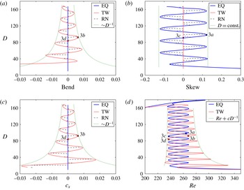
Bending (a), skewing (b) and wave speed (c) in comparison with the snaking in Reynolds number (d) for the equilibrium (EQ), travelling-wave (TW) and rung (RN) solutions at
 $L_{x}=3{\rm\pi}$
. Dotted lines show the
 $~D^{-1}$
envelope of wave speed and bending for the travelling wave and the constant-
 $D$
envelope of equilibrium skewing. In (d) two independent dotted lines of form
 $\mathit{Re}+cD^{-1}$
are shown. The values of
 $\mathit{Re}$
for the two lines were set as the lower and upper bounds of the equilibrium snaking curve (
 $\mathit{Re}=236$
and
 $\mathit{Re}=268$
), and the values of
 $c$
chosen to fit the envelope of the travelling-wave snaking curve. Labelled points correspond to pressure fields shown in figure 3. The breakdown of homoclinic snaking for
 $D\geqslant 160$
in (d) occurs when the spanwise growth of the localized solution reaches the edges of the
 $L_{z}=24{\rm\pi}$
computational domain.

Finite-size effects and
 $D^{-1}$
scaling are illustrated by Figure 4(a–c) which shows bending, skewing and wave speed as a function of
 $D$
, in comparison with the
 $\mathit{Re},D$
snaking in figure 4(d). Several features are notable. First, the solutions snake twice as fast in
 $\mathit{Re}$
as in skewing, bending or wave speed. This is due to the fact that the points of maximum magnitude in skewing and bending near the upper saddle-nodes in figure 1(b) have opposite sign. Second, the travelling wave’s bending and streamwise wave speed curves are nearly identical (figure 4
a,c) in all aspects, including position of minima, maxima and zeros,
 $D^{-1}$
scaling and, remarkably, magnitude. Sizable discrepancies between bending and wave speed occur only for
 $D<40$
, when the travelling wave consists of only a few copies of the interior periodic pattern (e.g. figure 2
a,b). The nearly identical magnitudes of non-dimensionalized bending and wave speed holds only for
 $L_{x}=3{\rm\pi}$
; at other
 $L_{x}$
the two quantities are strongly correlated but differ in magnitude by a factor of two or less.
Third, each of the travelling wave’s bending, wave speed and
 $\mathit{Re}$
snaking plots has a
 $D^{-1}$
envelope, whereas the corresponding plots for the equilibrium are constant in
 $D$
. As argued above, the constancy of the equilibrium’s behaviour in
 $D$
is due to the fact that, with linear skew, the solution can be extended in
 $z$
and thus bumped up to a higher position on the snaking curve at the same Reynolds number simply by adding another copy of the periodic pattern in the interior. Thus, the equilibrium snakes between constant bounds in Reynolds number and skewing. For the travelling wave, on the other hand, if we take the slope
 $\text{d}x/\text{d}z$
at the fronts as boundary conditions for constant interior curvature
 $\text{d}^{2}x/\text{d}z^{2}$
over a spanwise width that scales as
 $D$
, then the curvature must scale as
 $D^{-1}\text{d}x/\text{d}z$
. Given that the slope of the fronts oscillates between fixed bounds, the bending then must oscillate between bounds that scale as
 $D^{-1}$
. For large
 $D$
the curvature thus approaches zero, and the interior of the solution approaches a constant periodic pattern with skewing, bending and wave speed approaching zero.
At the point of zero bending (figure 3
d), the interior structure of the travelling wave is periodic and practically indistinguishable from the structure of the equilibrium at zero skew (figure 3
c). These points occur near low-
 $\mathit{Re}$
saddle-node bifurcations (figure 1
b), suggesting that the reason for the close match in the lower bound in
 $\mathit{Re}$
of the equilibrium and travelling-wave snaking regions is that the two solutions near the lower bifurcation point differ mainly in the orientation of one front. Lastly, the complete lack of symmetry in rung solutions means that they generally travel in
 $z$
as well as
 $x$
; however, the non-dimensionalized
 $z$
wave speeds are on the order of
 $10^{-5}$
.
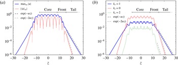
Core, front, tail structure of the localized solutions. (a) Maximum magnitude of streamwise velocity (
 $\max _{xy}|u|$
) and magnitude of mean streamwise velocity (
 $|\langle u\rangle _{xy}|$
) as a function of
 $z$
for the travelling wave at a point of maximum bend (
 $\mathit{Re}=275,D=48$
). The
 $|\langle u\rangle _{xy}|$
line is dotted when
 $\langle u\rangle _{xy}$
is negative. (b) Magnitude of the
 $k_{x}$
th streamwise Fourier mode for
 $k_{x}=0,1,2$
, as measured by the root-mean-square magnitude of
 $\hat{\boldsymbol{u}}_{k_{x}}(y,z)$
over
 $y$
as a function of
 $z$
. The computational domain is
 $3{\rm\pi}\times 24{\rm\pi}$
.

3.4 Core, front, tail structure
The localized solutions are formed from nearly periodic, large-amplitude core structures that taper into small-amplitude, exponentially decaying tails. The near periodicity of the core and the tapering fronts are apparent in figures 2 and 3. Figure 5 illustrates the small-amplitude tails as well, through logarithmic plots of velocity magnitude as a function of the spanwise coordinate
 $z$
. Figure 5(a) shows
 $|\langle u\rangle _{xy}|(z)$
, the magnitude of the
 $xy$
-average streamwise flow, and
 $\max _{xy}|u|(z)$
, the maximum over
 $x,y$
of the magnitude of the streamwise flow. Figure 5(b) shows the root-mean-square magnitude over
 $y$
of several streamwise Fourier modes as a function of
 $z$
. The central feature of these plots is the dominant
 $\exp (-{\it\alpha}|z|)$
scaling of the tails (where
 ${\it\alpha}=2{\rm\pi}/L_{x}$
), consistent with the linear analysis presented in Gibson & Brand (Reference Gibson and Brand2014). This analysis showed that for large
 $|z|$
, the tails of spanwise-localized, streamwise-periodic solutions are dominated by the
 $k_{x}=\pm 1$
streamwise Fourier modes, which take the form
 $\hat{\boldsymbol{u}}_{\pm 1}(y)\exp (\pm 2{\rm\pi}{\it\alpha}\text{i}(x-c_{x}t)-{\it\alpha}|z|)+\text{c.c.}$
The
 $\exp (-{\it\alpha}|z|)$
scaling of the
 $k_{x}=1$
mode is apparent in figure 5(b). The magnitude of the streamwise velocity in the tails (
 $\max _{xy}|u|$
) is dominated by the
 $k_{x}=\pm 1$
modes and thus has the same
 $\exp (-{\it\alpha}|z|)$
scaling, as shown in figure 5(a). The
 $\exp (-2{\it\alpha}|z|)$
scaling of the
 $k_{x}=0$
Fourier mode in figure 5(b) results from a resonance between the
 $k_{x}=\pm 1$
modes, which, when summed and substituted into the nonlinearity
 $\boldsymbol{u}\boldsymbol{\cdot }\boldsymbol{{\rm\nabla}}\boldsymbol{u}$
, produce an
 $\exp (-2{\it\alpha}|z|)$
forcing term in the
 $k_{x}=0$
momentum equation. The
 $k_{x}=0$
Fourier mode carries the
 $xy$
-average velocity, so
 $|\langle u\rangle _{xy}|$
in figure 5(a) has
 $\exp (-2{\it\alpha}|z|)$
scaling. The dominant
 $k_{x}=1$
mode thus produces a small, decaying, but non-zero and constant-sign mean streamwise velocity in the solution tails.
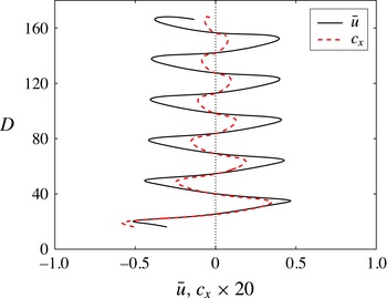
Net streamwise flow and wave speed of the travelling wave. The net streamwise flow
 $\bar{u}=(L_{x}L_{y})^{-1}\int _{xyz}u\,\text{d}x\,\text{d}y\,\text{d}z$
of the travelling wave at
 $L_{x}=3{\rm\pi}$
varies between roughly fixed bounds, in comparison with the
 $D^{-1}$
scaling of the wave speed. Wave speed is magnified by a factor of 20 for visibility.

The mean streamwise flow
 $\langle u\rangle _{xy}(z)$
of the travelling wave has a number of interesting features due to its
 $z$
-even symmetry, which results from the
 ${\it\sigma}_{z}{\it\tau}_{x}$
symmetry of the solution
 $\boldsymbol{u}$
. For one,
 $\langle u\rangle _{xy}(z)$
has the same sign in both tails (positive for the solution depicted in figure 5). In addition, even
 $z$
symmetry allows for imbalance between positive and negative mean streamwise velocity when integrated across the core and front regions. For example, there are three positive
 $\langle u\rangle _{xy}$
streaks and four negative large-magnitude streaks across the core and initial front of the travelling wave in figure 5, flanked by two lower-magnitude positive streaks. Integrating across the core, fronts and weak positive tails gives a net negative streamwise flow across the entire computational domain. Thus we have, with zero pressure gradient conditions, a steady-state solution whose streamwise flow is net negative in the interior, net positive in the tails and net negative over the whole flow domain. Figure 6 shows how the net streamwise flow
 $\bar{u}=1/(L_{x}L_{y})\int _{xyz}u\,\text{d}x\,\text{d}y\,\text{d}z$
varies along the snaking curve (again, the lack of
 $L_{z}$
normalization provides for a measure of the deviation from laminar flow that is insensitive to the computational domain). Note that
 $\bar{u}$
varies between roughly fixed bounds as the spanwise width (
 $D$
) increases, because it results from an
 $N$
versus
 $N+1$
imbalance of large-magnitude streamwise streaks of opposite sign. This is in contrast to wave speed and bending, which result from balances between the fixed-sized fronts and the increasing core and therefore scale as
 $D^{-1}$
. For the localized equilibrium solution
 $\bar{u}$
is zero and the streamwise flows in the
 $\pm z$
tails have opposing sign, due to
 ${\it\sigma}_{xyz}$
symmetry of
 $\boldsymbol{u}$
and consequent odd symmetry in
 $\langle u\rangle _{xy}(z)$
.
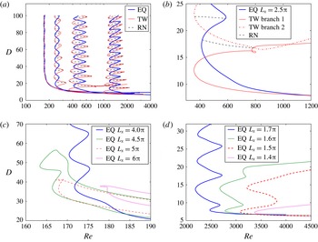
Snaking as a function of streamwise wavelength
 $L_{x}$
. (a) Snaking curves for the equilibrium (EQ), travelling-wave (TW) and rung (RN) solutions at
 $L_{x}=4{\rm\pi}$
,
 $3{\rm\pi}$
,
 $2.5{\rm\pi}$
and
 $2{\rm\pi}$
, with the snaking curves moving upwards in
 $Re$
as
 $L_{x}$
decreases. (b) Detail of snaking curve for
 $L_{x}=2.5{\rm\pi}$
. (c) Snaking breakdown for
 $L_{x}>4.2{\rm\pi}$
. (d) Snaking breakdown for
 $L_{x}<1.7{\rm\pi}$
.

4 Effects of varying streamwise wavelength
4.1 Snaking region and snaking breakdown
In this section we examine the effects of changing the streamwise wavelength
 $L_{x}$
. The central results are that snaking is robust in
 $L_{x}$
over the range
 $1.7{\rm\pi}\leqslant L_{x}\leqslant 4.2{\rm\pi}$
or
 $0.48\leqslant {\it\alpha}\leqslant 1.2$
, and that the snaking region moves upward in Reynolds number with decreasing
 $L_{x}$
, with snaking observed over the range
 $165\leqslant \mathit{Re}\leqslant 2700$
. Each of these bounds is reported to two digits accuracy. Thus, the localized solutions and the homoclinic snaking behaviour occur over a wide range of Reynolds numbers, including the
 $\mathit{Re}\approx 300{-}400$
range where Barkley & Tuckerman (Reference Barkley and Tuckerman2005) and Duguet et al. (Reference Duguet, Schlatter and Henningson2010) observed laminar–turbulent patterns in plane Couette flow. Figure 7(a) shows snaking curves for the localized solutions at a variety of streamwise wavelengths. The interlinked snaking structure of the equilibrium, travelling-wave and rung solutions is preserved under variation in
 $L_{x}$
with the following trends. As
 $L_{x}$
decreases, the snaking region moves upwards in
 $\mathit{Re}$
and widens. As in the
 $L_{x}=3{\rm\pi}$
case, the width in
 $\mathit{Re}$
of any given equilibrium snaking curve is constant in
 $D$
, whereas the amplitude of the travelling-wave snaking region decays as
 $D^{-1}$
. For
 $L_{x}=4{\rm\pi}$
the excess amplitude of travelling-wave snaking region over the equilibrium is too small to be observed.
Figure 7(c,d) illustrates the breakdown of homoclinic snaking outside the range
 $1.7{\rm\pi}\leqslant L_{x}\leqslant 4.2{\rm\pi}$
. Above and below these bounds, the solutions are unable to grow additional structure indefinitely at the fronts. Instead of snaking indefinitely, the solution curves turn around and continue to higher Reynolds numbers at roughly constant spanwise width. For
 $L_{x}$
values just beyond the given range, the solutions snake a few times before turning around, as illustrated by the
 $L_{x}=1.6{\rm\pi}$
and
 $4.5{\rm\pi}$
curves in figure 7(c,d). Figure 7(b) illustrates a peculiar defect in the homoclinic snaking scenario that occurs at the particular value
 $L_{x}=2.5{\rm\pi}$
. At this streamwise wavelength the snaking curve for the travelling wave solution has two distinct branches. The solid curve labelled ‘TW branch 1’ was continued downward from high Reynolds numbers and small spanwise widths (
 $D\approx 7$
) where it connects smoothly to the other snaking curves via continuation in
 $L_{x}$
. However this solution branch does not snake; rather it turns around in a saddle-node bifurcation and continues back to at least
 $\mathit{Re}=2000$
at finite spanwise width. In contrast the dot-dashed curve labelled ‘TW branch 2’ does snake upward in
 $D$
; it constitutes the bulk of the
 $L_{x}=2.5{\rm\pi}$
travelling wave snaking curve shown in figure 7(a). The branch-2 travelling wave was obtained from the endpoint of the rung solution at
 $\mathit{Re}\approx 360$
,
 $D\approx 22.5$
. At fixed
 $L_{x}=2.5{\rm\pi}$
, the two branches remain distinct to
 $\mathit{Re}=2000$
at least, though they can be connected by continuation in the two parameters
 $\mathit{Re},L_{x}$
. We have observed similar defects in snaking curves at several other values of
 $L_{x}$
(not shown). It is possible that the snaking breakdown observed for
 $L_{x}<1.7{\rm\pi}$
and
 $L_{x}>4.2{\rm\pi}$
is of this type. That is, there might be branches of the solution curves for such
 $L_{x}$
at higher
 $D$
that are disconnected from the non-snaking solution curves pictured in figure 7(c,d). We have confirmed this in a few particular instances; for example, by continuing a
 $D=90$
solution from
 $L_{x}=4{\rm\pi}$
to
 $L_{x}=4.3{\rm\pi}$
, where it forms an isola above and disconnected from a lower-
 $D$
solution branch.
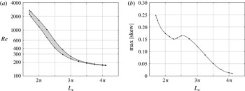
Snaking region and maximum skewing as a function of wavelength. (a) The snaking region in
 $\mathit{Re}$
as a function of
 $L_{x}$
for the localized equilibrium. The shaded region indicates the range of
 $\mathit{Re}$
within which snaking occurs at a given
 $L_{x}$
. (b) Maximum magnitude of skewing of the equilibrium solution as a function of
 $L_{x}$
. For both figures, dots mark measured values and the curves are interpolated.

Figure 8(a) shows the snaking region of the localized equilibrium in Reynolds number as a function of the streamwise wavelength
 $L_{x}$
. Snaking also occurs when the solutions are continued in
 $L_{x}$
with
 $\mathit{Re}$
fixed, within the same shaded
 $\mathit{Re},L_{x}$
parameter regions. The boundaries of the snaking region in
 $\mathit{Re}$
decrease roughly exponentially with
 $L_{x}$
for
 $L_{x}\leqslant 3{\rm\pi}$
. As
 $L_{x}$
increases to
 $4.2{\rm\pi}$
, the lower bound of the snaking region approaches a minimum of roughly
 $\mathit{Re}=165$
. It is notable that the breakdown of snaking at
 $L_{x}\approx 4{\rm\pi}$
closely coincides with the vanishing of the amplitude of the
 $D^{-1}$
scaling in the travelling wave’s snaking region, as seen figure 7(a). Similarly, the magnitudes of bending and skewing decrease with increasing
 $L_{x}$
, and at
 $L_{x}\approx 4{\rm\pi}$
are too small to be observed in plots of the velocity or pressure fields. Figure 8(b) shows the magnitude of the oscillation in skewing over the snaking curve as a function of
 $L_{x}$
, as measured by the slopes of the lines through pressure minima and maxima, as shown in figure 3(b). It is possible that the breakdown of snaking for
 $L_{x}>4.2{\rm\pi}$
is related to the disappearance of these effects at
 $L_{x}\approx 4{\rm\pi}$
.
A defect in a localized solution after the breakdown of snaking. The streamwise velocity of the
 $L_{x}=4.5{\rm\pi}$
localized equilibrium solution is shown for
 $\mathit{Re}=175$
and
 $D=37$
, on the upper branch of the
 $L_{x}=4.5{\rm\pi}$
curve in figure 7(c). Plotting conventions are the same as in figure 2.

The breakdown of snaking for both
 $L_{x}<1.7{\rm\pi}$
and
 $L_{x}>4.2{\rm\pi}$
appears to be associated with the development of defects in the interior pattern of the solution. Instead of continuing to snake by growing additional structure at the fronts, the solutions develop defects at the spanwise centre and continue to high Reynolds numbers. Figure 9 shows the defect in the
 $L_{x}=4.5{\rm\pi}$
equilibrium solution at
 $(\mathit{Re},D)=(175,37)$
, on the upper branch of the
 $L_{x}=4.5{\rm\pi}$
curve in figure 7(c). Defects in the
 $L_{x}<1.7{\rm\pi}$
solutions are quite weak and appear as subtle variations in visualizations of the velocity and pressure fields. The breakdown of snaking and development of central defects observed here is quite similar to that observed by Kao et al. (Reference Kao, Beaume and Knobloch2014) for the Swift–Hohenberg equation with heterogeneous forcing (see their figure 8).
4.2 Stability
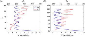
Figure 10 shows the number of unstable eigenvalues of the
 $L_{x}=3{\rm\pi}$
and
 $4{\rm\pi}$
equilibrium solutions in comparison with their
 $\mathit{Re},D$
snaking curves. At
 $L_{x}=3{\rm\pi}$
the equilibrium has a minimum of two or three unstable eigenvalues at small spanwise width (low
 $D$
). Thus, it is not strictly an edge state of the flow (Schneider & Eckhardt Reference Schneider and Eckhardt2006; Skufca, Yorke & Eckhardt Reference Skufca, Yorke and Eckhardt2006). However, one of the corresponding unstable eigenfunctions is antisymmetric, making the solution an edge state of the flow when constrained to
 ${\it\sigma}_{xyz}$
symmetry. In both cases there is a general trend toward more unstable modes as the solution grows in spanwise width. The
 $L_{x}=3{\rm\pi}$
,
 $D\approx 100$
solutions depicted in figure 3(a,c) have
 $O(20)$
unstable eigenvalues. Superimposed on this general trend is an oscillation in which the number of unstable eigenvalues increases and decreases along the snaking curve. For both cases the local maxima (minima) in the number of unstable modes occur at points of maximum (minimum) skewing magnitude. In other words, strongly skewed solutions are more unstable than solutions with weak or zero skew. The same trends occur at
 $L_{x}=2{\rm\pi}$
, with the smallest-width solution starting with six unstable eigenvalues. The trend towards more instabilities with increasing spanwise width contrasts with the one-dimensional Swift–Hohenberg equation, for which the number of unstable eigenvalues oscillates between zero and two with each cycle along the snaking curve (Burke & Knobloch Reference Burke and Knobloch2007a
,Reference Burke and Knobloch
b
).
Instability of the localized equilibrium in relation to spanwise width and wavelength. The number of unstable eigenvalues of the localized equilibrium solution as a function of spanwise width (
 $D$
), overlaid on the
 $\mathit{Re},D$
snaking curve for (a)
 $L_{x}=3{\rm\pi}$
and (b)
 $L_{x}=4{\rm\pi}$
.

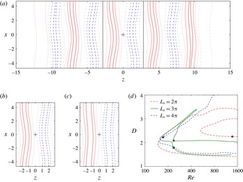
Extraction of the interior periodic pattern of a spanwise localized solution. (a) The spanwise-localized equilibrium at point of zero skew,
 $L_{x}=3{\rm\pi}$
,
 $D=47$
and
 $\mathit{Re}=237$
. Vertical lines at
 $z=\pm 2.85$
mark one copy of the nearly periodic interior structure. (b) A periodic equilibrium obtained by Newton–Krylov refinement of the structure extracted from (a), with
 $L_{x},L_{z}=3{\rm\pi},5.7$
and
 $\mathit{Re}=237$
. (c) The lower-branch NBCW equilibrium at the same parameter values as (b), obtained by continuation. Plotting conventions for (a–c) are the same as in figure 2. (d) Bifurcation curves for the interior periodic pattern and the NBCW equilibrium for
 $L_{x}=2{\rm\pi},3{\rm\pi}$
and
 $4{\rm\pi}$
and aspect ratios
 $L_{x}/L_{z}=1.74,1.65,1.74$
respectively. The periodic interior pattern and lower-branch NBCW equilibrium shown in (b,c) are marked on the
 $L_{x}=3{\rm\pi}$
curve with a circle and square respectively. The interior patterns extracted from spanwise-localized equilibrium at
 $L_{x}=2{\rm\pi}$
and
 $4{\rm\pi}$
are also marked with circles.

5 The periodic pattern of the core
5.1 Relation of the periodic pattern to the NBCW solution
Schneider et al. (Reference Schneider, Gibson and Burke2010a
,Reference Schneider, Marinc and Eckhardt
b
) established that the snaking solutions are closely related to the NBCW equilibria, in that they result from a localizing bifurcation of NBCW and resemble the structure of NBCW in their interior. However, the relationship between the core structure and the NBCW solutions is more complicated than previously supposed. In particular, for
 $L_{x}\leqslant 3{\rm\pi}$
, the interior pattern and the NBCW solution lie on distinct solution curves when continued in Reynolds number, although these curves can be connected by continuation in the higher-dimensional parameter space
 $L_{x},L_{z},\mathit{Re}$
.
To compare the interior pattern with the NBCW solution, we extracted one copy of the interior pattern of the equilibrium at a variety of
 $L_{x}$
values, as illustrated for
 $L_{x}=3{\rm\pi}$
in figure 11. We begin in figure 11(a) with a streamwise-localized equilibrium solution at a point along the snaking curve of zero skew, in order to maximize the spanwise periodicity of the interior pattern. The natural spanwise wavelength
 $\hat{L}_{z}=5.70$
of the interior pattern was determined by finding the zeros of
 $\langle u\rangle _{xy}(z)$
on either side of
 $z=0$
. In figure 11(a) these points are marked with vertical lines at
 $z=\pm 2.85$
. The nearly periodic interior pattern was then interpolated onto uniformly spaced grid points for a spanwise periodic computational domain of width
 $L_{z}=5.70$
and refined with a Newton–Krylov search to the equilibrium shown in figure 11(b). We performed this operation to find the equilibrium solution corresponding to the interior periodic pattern at several streamwise wavelengths in the range
 $2{\rm\pi}\leqslant L_{x}\leqslant 4{\rm\pi}$
. In each case the divergence and the Gibbs phenomenon of the interpolated field were small and the Newton–Krylov refinement converged quickly onto an equilibrium solution. The natural aspect ratio of the interior pattern was always found to be in the range
 $1.65\leqslant L_{x}/\hat{L}_{z}\leqslant 1.75$
.
Figure 11(d) shows bifurcation diagrams for the NBCW solution and periodic equilibria computed from the interior pattern for
 $L_{x}=2{\rm\pi}$
,
 $3{\rm\pi}$
and
 $4{\rm\pi}$
. Since these solutions are periodic in both the spanwise and streamwise directions, we use the conventional measure of energy dissipation and wall shear rate
 $$\begin{eqnarray}\displaystyle D_{tot}=I_{tot}=\frac{1}{2L_{x}L_{z}}\int _{-L_{x}/2}^{L_{x}/2}\int _{-L_{z}/2}^{L_{z}/2}\left(\left.\frac{\partial u_{tot}}{\partial y}\right|_{y=-1}+\left.\frac{\partial u_{tot}}{\partial y}\right|_{y=1}\right)\,\text{d}x\,\text{d}z. & & \displaystyle\end{eqnarray}$$
The circles mark the
 $\mathit{Re},D_{tot}$
positions of the interior-pattern equilibrium solutions computed from localized solutions as described above, and the lines indicate the parametric continuation of these solutions in
 $\mathit{Re}$
. For
 $L_{x}=4{\rm\pi}$
it was straightforward to continue the NBCW solution to the same aspect ratio and Reynolds number and confirm that the pattern and the NBCW solution were the same. However, as
 $L_{x}$
decreases, the upper portion of the solution curve pinches off at a codimension-two bifurcation point near
 $L_{x}=3{\rm\pi}$
,
 $\mathit{Re}=237$
, leaving the interior pattern and NBCW on distinct solution curves. This pinching occurs at an
 $L_{x}$
value just below the
 $L_{x}=3{\rm\pi}$
solution curve shown in figure 11(d). For
 $L_{x}=2{\rm\pi}$
, the solution curves for the interior pattern (dash-dot line marked with a circle) and the NBCW solution (dash-dot, no marker) are distinct.
A winding equilibrium solution of plane Couette flow at
 $\mathit{Re}=268$
. The solution is strictly periodic in
 $x$
but has
 $z$
periodicity involving a phase shift in
 $x$
of the form
 $\boldsymbol{u}(x,y,z+5.642)=\boldsymbol{u}(x-0.496,y,z)$
. A total of 19 copies of the
 $3{\rm\pi}\times 5.642$
pattern fit in the
 $3{\rm\pi}\times 107.2$
periodic computational domain. Contours of the midplane pressure field
 $p(x,z)$
are shown with the same plotting conventions as figure 3.

5.2 A winding solution of plane Couette flow
It is possible to compute a spatially periodic winding solution from a skewed localized equilibrium, that is, a solution with fundamental domain size
 $L_{x},\hat{L}_{z}$
that is strictly periodic in
 $x$
, but whose
 $z$
periodicity involves a phase shift in
 $x$
,
 $$\begin{eqnarray}\displaystyle \boldsymbol{u}(x,y,z+\hat{L}_{z})=\boldsymbol{u}(x-{\rm\Delta}x,y,z). & & \displaystyle\end{eqnarray}$$
One such solution is illustrated in figure 12. The solution was computed starting with a localized equilibrium with strong skewing, like that shown in figure 3(a). An iterative process of continuation in the computational domain length
 $L_{z}$
and adjustment of skewing by continuation in Reynolds number was performed to find a localized equilibrium whose interior pattern divided the computational domain evenly (
 $L_{z}/\hat{L}_{z}\doteq N\in \mathbb{Z}$
) and whose skew precisely aligned with the
 $x,z$
diagonal of the computational domain.
 $N$
copies of this winding interior pattern were then interpolated onto the computational domain as shown in figure 12 and refined with Newton–Krylov search. The resulting winding solution shown in figure 12 at
 $\mathit{Re}=268$
has an
 $L_{x}=3{\rm\pi},L_{z}=107.2$
computational domain and
 $N=19$
, giving
 $\hat{L}_{z}=L_{z}/N\doteq 5.462$
,
 ${\rm\Delta}x=L_{x}/N\doteq 0.496$
, and winding symmetry
 $\boldsymbol{u}(x,y,z+5.642)=\boldsymbol{u}(x-0.496,y,z)$
. The winding symmetry and
 $\boldsymbol{u}={\it\sigma}_{xyz}\boldsymbol{u}$
were enforced during the Newton–Krylov search. It is likely that other winding solutions of shear flows could be computed without recourse to skewed localized solutions, simply by applying skewing coordinate transformations to known spatially periodic solutions and refining with Newton–Krylov search.
6 Conclusions
We have shown that homoclinic snaking is robust under changes in streamwise wavelength for the spanwise-localized solutions of plane Couette flow of Schneider et al. (Reference Schneider, Gibson and Burke2010a
). Homoclinic snaking occurs for these solutions over streamwise wavelengths in the range
 $1.7{\rm\pi}\leqslant L_{x}\leqslant 4.2{\rm\pi}$
and Reynolds numbers
 $165\leqslant \mathit{Re}\leqslant 2700$
, and the snaking region moves upwards in
 $\mathit{Re}$
as
 $L_{x}$
decreases. The localized equilibrium, travelling-wave and rung solutions thus exist at arbitrarily large spanwise widths over a wide range of Reynolds numbers. Several new properties of the solutions become apparent as
 $L_{x}$
decreases below
 $4{\rm\pi}$
, most importantly the linear skewing of the equilibrium and quadratic bending of the travelling wave. The travelling wave exhibits finite-size effects such as
 $D^{-1}$
scaling of the bending, wave speed and snaking region, due to the non-uniform structure in the solution core induced by the quadratic bending. The linear skewing of the localized equilibrium solution, on the other hand, induces no such finite-size effects. Its core region is very nearly periodic, close enough that a strictly periodic winding solution can be easily developed from it. The number of instabilities of the localized solutions increase with Reynolds number, with spanwise width and with skewing. Thus, at a fixed Reynolds number, from a statistical viewpoint one would expect narrow patches of the localized pattern to appear more frequently than wide patches, and with weak rather than strong skewing.
The homoclinic snaking of these localized solutions suggests the Navier–Stokes equations might be related to the Swift–Hohenberg equation under plane Couette flow conditions and for certain parameter ranges and flow states. A primary motivation for this paper is to clarify the parameter ranges and solution structures for which this connection might occur. Our results indicate that homoclinic snaking is a finite-Reynolds, finite-wavelength effect and that the streamwise wavelength and the Reynolds-number snaking region are strongly coupled. Thus it is unlikely that an analytic understanding of homoclinic snaking in shear flows will be found via asymptotic analysis in large-Reynolds or large-wavelength limits. If the spanwise-localized solutions are to be understood as a long-wavelength modulation of a small-wavelength, spanwise-periodic pattern, our results show that the periodic pattern is a form of the NBCW solution at aspect ratio
 $L_{x}/L_{z}\approx 1.7$
. For
 $L_{x}<3{\rm\pi}$
, under continuation in Reynolds number, the periodic pattern lies on a solution curve distinct from the widely studied NBCW lower-branch solution.
We see no clear connection between the skewing of the localized equilibrium solution and the skewed laminar–turbulent patterns observed in plane Couette flow by Barkley & Tuckerman (Reference Barkley and Tuckerman2005, Reference Barkley and Tuckerman2007) and Duguet et al. (Reference Duguet, Schlatter and Henningson2010). The localized solutions exist over a much wider range of Reynolds numbers than the
 $300\leqslant \mathit{Re}\leqslant 400$
range of observed laminar–non-laminar patterns. As shown in figure 7(a), this range depends very much on the streamwise length
 $L_{x}$
. For the
 $L_{x}=3{\rm\pi}$
length studied in § 3, the Reynolds number range for snaking is very similar to
 $300\leqslant \mathit{Re}\leqslant 400$
.
Also, the skewing of the localized equilibrium is a streamwise phase shift of the interior pattern as function of spanwise coordinate, whereas the skewing of observed laminar–turbulent patterns is in the orientation of the boundary between the turbulent patches and the surrounding laminar flow. In contrast, the localized solutions studied here are strictly streamwise periodic, and thus have laminar–non-laminar boundaries aligned with the streamwise direction. One potential route to finding invariant solutions with skewed laminar–non-laminar boundaries would be to find a streamwise-localized form of a winding solution like that described in § 5.2. However, the angles observed in the literature for laminar–turbulent patterns are quite different than those observed here. These are typically reported as the angle
 ${\it\beta}$
between the laminar–turbulent boundary and the streamwise
 $x$
direction;
 ${\it\beta}$
and skew
 $\text{d}x/\text{d}z$
are related by
 ${\it\beta}=\cot ^{-1}(\text{d}x/\text{d}z)$
. Duguet et al. (Reference Duguet, Schlatter and Henningson2010) report a range of
 $20^{\circ }\leqslant {\it\beta}\leqslant 70^{\circ }$
for the boundaries of turbulent patches in plane Couette flow for
 $324\leqslant \mathit{Re}\leqslant 380$
. Barkley & Tuckerman (Reference Barkley and Tuckerman2005) find the range
 $15^{\circ }\leqslant {\it\beta}\leqslant 65^{\circ }$
for laminar–turbulent patterns in a tilted minimal flow unit at
 $\mathit{Re}=350$
. From figure 8, the localized equilibria that snake within this range of Reynolds numbers have skew
 $0\leqslant |\text{d}x/\text{d}z|\leqslant 0.15$
or
 $81\leqslant {\it\beta}\leqslant 90$
.
Acknowledgements
The authors thank J. Burke and E. Knobloch for illuminating conversations, and J. Burke for assistance in the numerical calculations. We are grateful to reviewer 1 for insightful comments and for pointing out several interesting connections to previous literature. T.M.S. was supported by the Swiss National Science Foundation under grant no. 200021-160088. Computations were performed on Trillian, a Cray XE6m-200 supercomputer at the University of New Hampshire supported by the Major Research Instrumentation program of the United States National Science Foundation under grant PHY-1229408.