1 Introduction
The stationary plasma thruster (SPT) put forward by Morozov is an electrostatic thruster used for spacecraft propulsion. In SPT the magnetic field is primarily used to enable electron impact ionization and the development of an axial electric field in the channel. The ceramic wall erosion of SPT is one of the most important factors limiting its lifetime. In SPT, ions are accelerated by the presheath and sheath. Some of these can impact the walls with high enough energies and sputter the wall ceramic material away (Cheng & Sanchez Reference Cheng and Sanchez2008). Many experiments have been done to study the effects of plasma sputtering on boron nitride ceramic for SPT (Zidar & Rovey Reference Zidar and Rovey2012; Alexander, Joshua & Hilmas Reference Alexander, Joshua and Hilmas2014; Satonik, Rovey & Hilmas Reference Satonik, Rovey and Hilmas2014). The maximum erosion rate is near the exhaust region due to the maximum ion average energy there. After the local ceramic material is totally sputtered away, the ions will directly collide with the magnetic pole and erode it. Then the magnetic field topology will be changed greatly, which makes the performance of the thruster become worse.
Due to the importance of erosion in SPT, many experimental and simulated works have been done to study the erosion mechanism and predict the life of SPT (Yamamoto et al.
Reference Yamamoto, Yokota, Matsui, Komurasaki and Arakawa2005; Gorshkov, Dyshlyuk & Shagaida Reference Gorshkov, Dyshlyuk and Shagaida2007; Sommier et al.
Reference Sommier, Scharfe, Gascon, Cappelli and Fernandez2007; Koizumi, Komurasaki & Arakawa Reference Koizumi, Komurasaki and Arakawa2008; Cho, Komurasaki & Arakawa Reference Cho, Komurasaki and Arakawa2013a
). Those studies on erosion in SPT now mainly focus on the radial evolution of the dielectric walls and predicting the life of SPT. Besides, magnetically shielded Hall thrusters are designed to achieve a longer lifespan than traditional Hall thrusters by optimizing the magnetic topology and reducing wall erosion (Grimaud & Mazouffre Reference Grimaud and Mazouffre2017; Lou & Mazouffre Reference Lou and Mazouffre2018). However, the azimuthal erosion, known as anomalous erosion, which was found in 1990s after long-term experiments (
 ${\sim}$
1000 h) makes the erosion in SPT different from the ordinary erosion process (Morozov Reference Morozov2003).
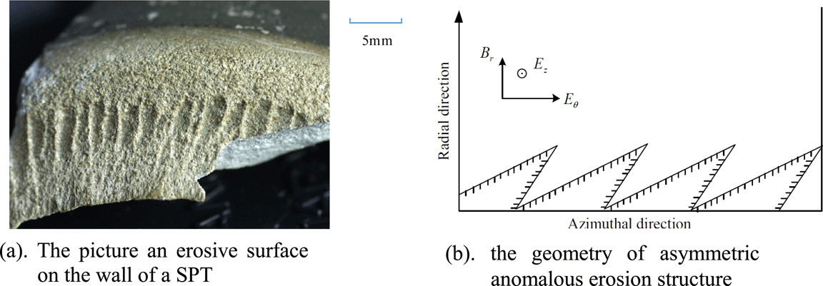
The anomalous erosion has two main characteristics. First, it is a periodic set of scratches oriented along the thruster axis, as shown in figure 1(a). The spatial period is of the order of the electron Larmor radius, i.e. approximately 1 mm. Furthermore, the scratches are slightly tilted in a direction opposite to the azimuthal electron drift with an asymmetric structure, as shown in figure 1(b). The formative mechanism for the anomalous erosion has been studied by many researchers but is not clear yet (Morozov Reference Morozov2003; Taccogna et al. Reference Taccogna, Longo, Capitelli and Schneider2009; Tsikata et al. Reference Tsikata, Honore, Lemoine and Gresillon2010; Cho et al. Reference Cho, Yokota, Komurasaki and Arakawa2013b ).
(a) Picture of an eroded surface on the wall of a SPT. (b) The geometry of asymmetric anomalous erosion structure.

Morozov et al. (Morozov Reference Morozov2003) investigated this phenomenon and put forward that the periodic anomalous erosion structure is formed due to the electrons’ azimuthal periodic movements. However, recent experimental results have shown that the electrons have a negligible effect on the erosion of dielectric walls in SPT (Morozov Reference Morozov2003). Some other researchers took the azimuthal plasma oscillation as the main mechanism for anomalous erosion (Taccogna et al. Reference Taccogna, Longo, Capitelli and Schneider2009; Tsikata et al. Reference Tsikata, Honore, Lemoine and Gresillon2010). Recently, different azimuthal oscillation modes have been proposed theoretically and captured by experiments (Taccogna et al. Reference Taccogna, Longo, Capitelli and Schneider2009; Tsikata et al. Reference Tsikata, Lemoine, Pisarev and Gresillon2009; Zhang et al. Reference Zhang, Yu, Ding and Li.2011). However, some experiments have been done to prove that the erosion of ceramic by electrons cannot be ignored for SPT and it may be a candidate to explain the anomalous erosion present on the exit plane of hall effect thruster (HET) (Sarrailh et al. Reference Sarrailh, Belhaj, Inguimbert and Boniface2017). Now, there is no systematic research on the formation mechanism of anomalous erosion yet. While for the asymmetric structure of the anomalous erosion, there have been no explanations as yet.
In this article, the correlation between the azimuthal irregular sheath profile and asymmetric anomalous erosion structure will be analysed. It is found that the asymmetric anomalous erosion structure is caused by ion bombardment. The electron Hall drift plays a key rule during this process.
2 Numerical model
In order to study the effect of electron Hall drift on the sheath profile and erosion structure, the sheath structure is simulated by a two-dimensional radial and azimuthal (
 $r,\unicode[STIX]{x1D703}$
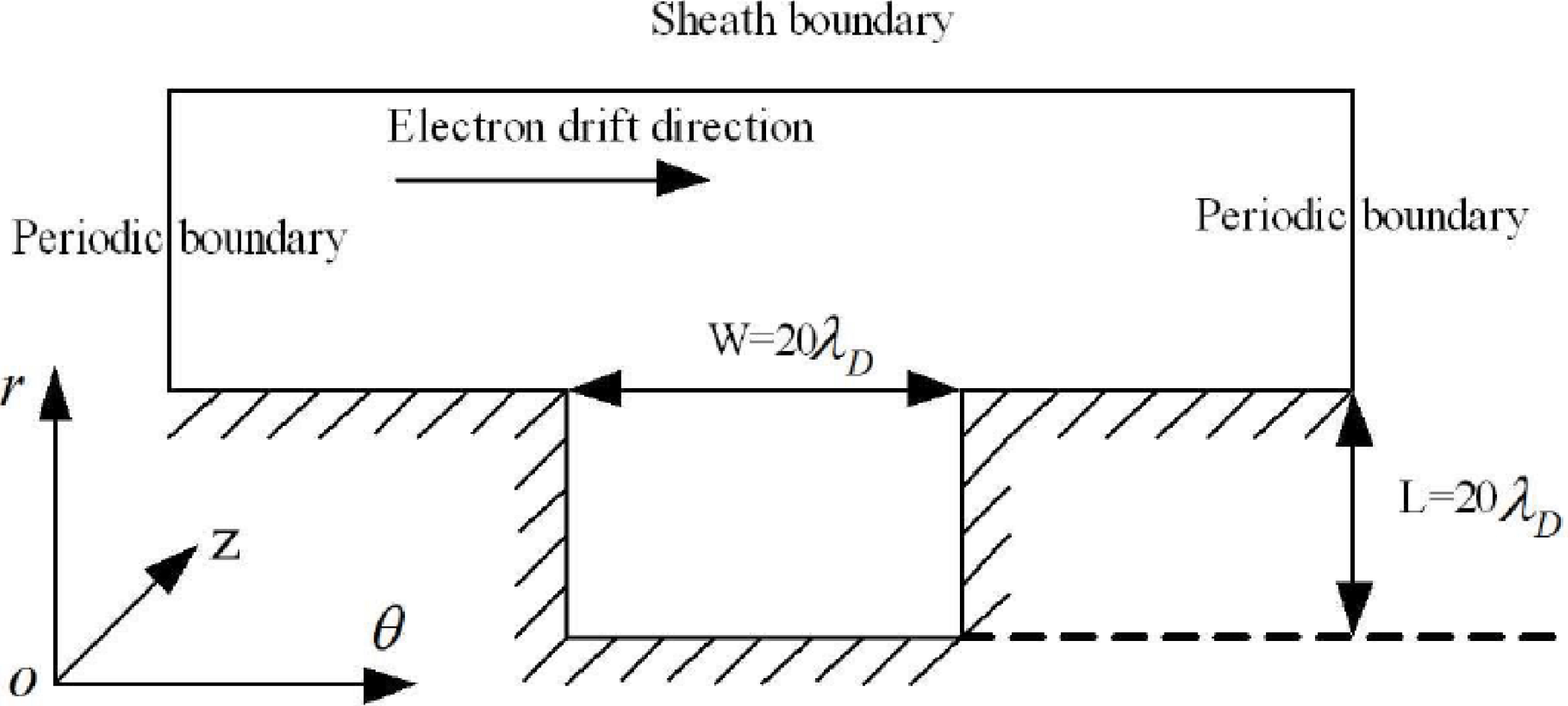
) kinetic electrostatic particle-in-cell (PIC) code. According to the experimental results, the anomalous erosion structure can be found after approximately 100 h of operation. Therefore, supposing that the initial azimuthal periodic erosion has been formed, a sheath with an azimuthal groove structure is modelled in the article. The simulation domain and boundary conditions are shown in figure 2.
Computational model.

The ‘local-field approximation’ is used, neglecting the effects of axial gradients. Only the axial electric field (
 $E_{z}$
) and radial magnetic field (
 $B_{r}$
) are considered. Based on experiments, the following homogeneous magnetic and electric field parameters in the acceleration region are used in the model:
 $B_{r}=200~\text{G}$
,
 $E_{z}=4\times 10^{4}$
V m
 $^{-1}$
. Therefore, the azimuthal drift velocity will be formed with a value
 $V_{d}=E_{z}/B_{r}=2\times 10^{6}$
m s
 $^{-1}$
. The model was proven to have enough accuracy in our former works (Yu et al.
Reference Yu, Liu, Yan and Liu2008; Liu et al.
Reference Liu, Wu, Yu, Cao and Duan2010; Zhang et al.
Reference Zhang, Yu, Ding and Li.2011) and has been improved to consider the magnetic effect. Electrons are moved by discretizing the equations of motion using the leapfrog method of Boris (Birdsall & Langdon Reference Birdsall and Langdon1991). The potential at the sheath boundary is set to be zero. The electric field is solved using the Poisson equation. The dynamic alternating direction implicit (DADI) method is used to solve the Poisson equation (Doss & Miller Reference Doss and Miller1979). The secondary electron emission model is similar to that in our former model (Zhang et al.
Reference Zhang, Yu, Ding and Li.2011). The electric field at the dielectric walls is solved according to Vahedi’s method proposed in Vahedi & DiPeso (Reference Vahedi and DiPeso1997). A rectangular cell is adopted in this model and there are 100 macroparticles per cell. The time step is
 $\unicode[STIX]{x0394}t\approx 0.1\unicode[STIX]{x1D714}_{p}^{-1}$
, mesh size is approximately
 $0.5\unicode[STIX]{x1D706}_{D}$
;
 $\unicode[STIX]{x1D714}_{p}$
and
 $\unicode[STIX]{x1D706}_{D}$
are the plasma oscillation frequency and Debye length, respectively. The simulation region is initially empty. Schwager’s planar source model is used to inject the particles with a half-Maxwellian velocity distribution (Schwager & Birdsall Reference Schwager and Birdsall1990). The plasma parameters near the sheath boundary are uniform with electron temperature
 $T_{e0}=18$
eV, ion temperature
 $T_{i0}=1$
eV and plasma density
 $n_{0}=2\times 10^{17}~\text{m}^{-3}$
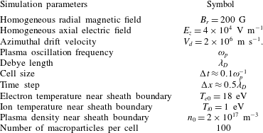
. The electron Hall drift velocity is added when electrons are ejected into the model. The height and the width of the groove are both 0.5 mm. The characteristics of this model are summarized in table 1.
Plasma parameter distribution when considering a crossed magnetic and electric field.

Simulation parameters.

3 Simulation results
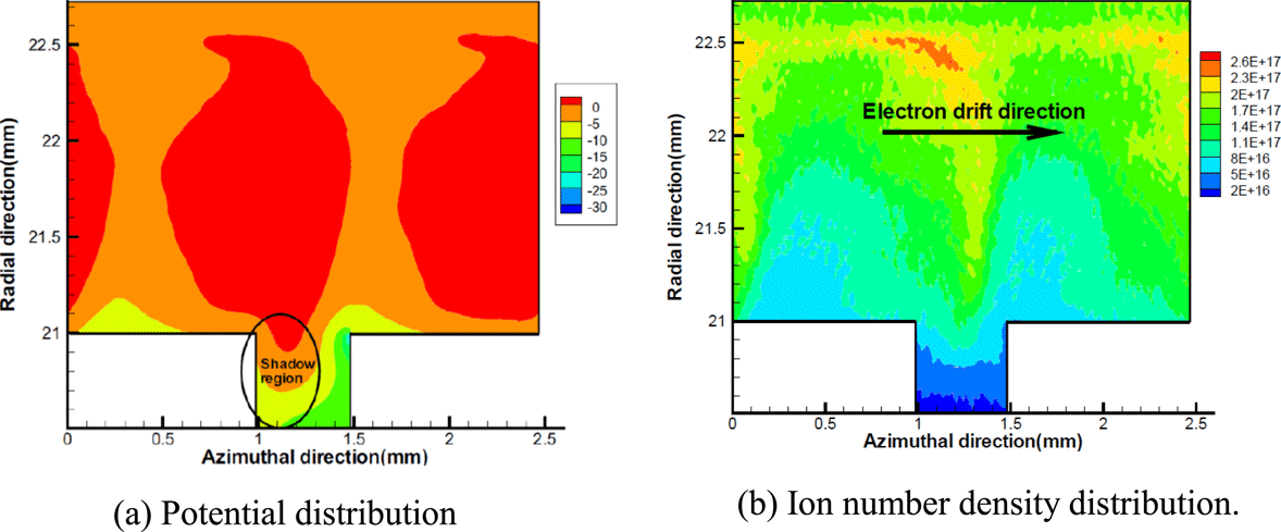
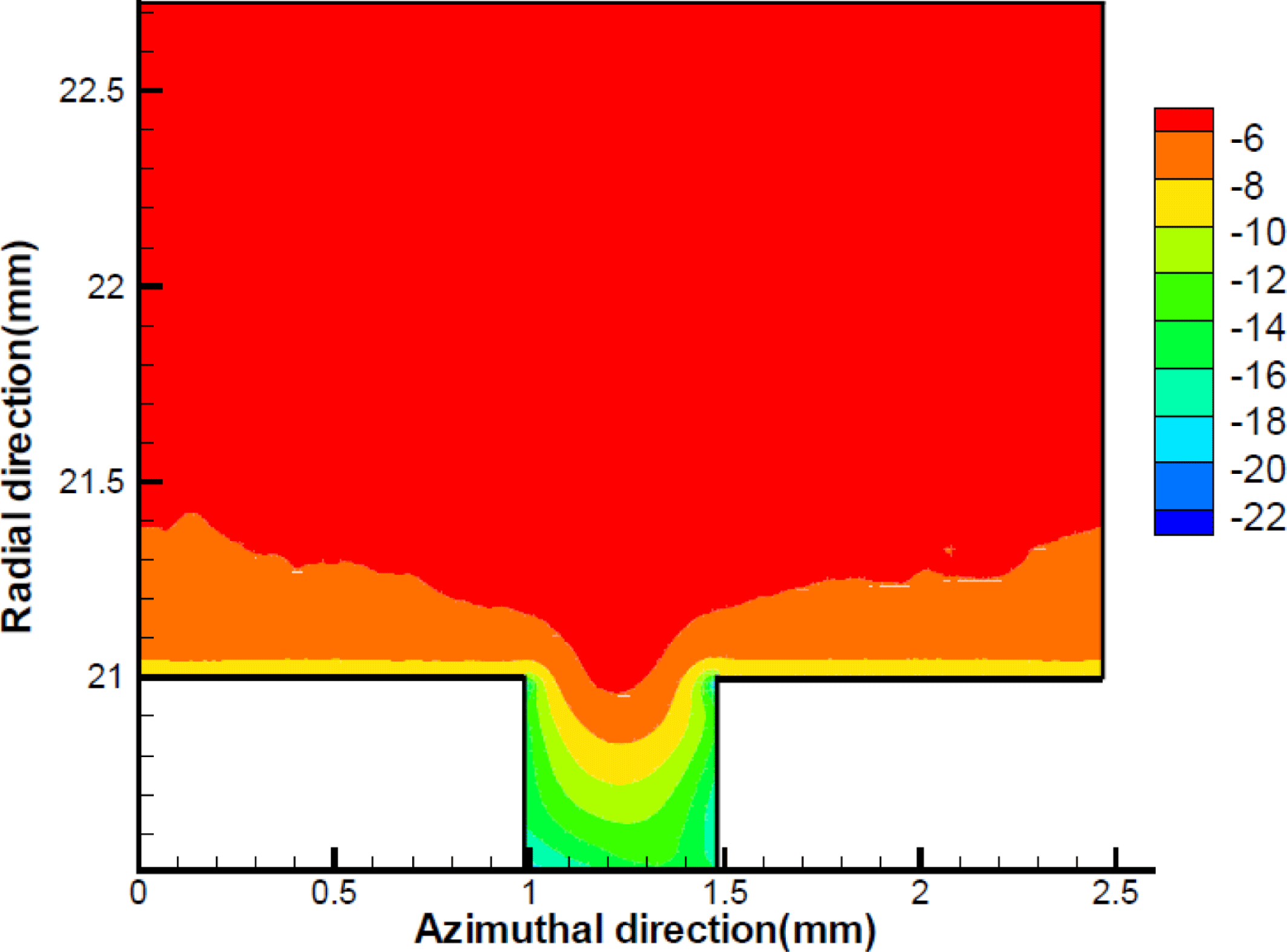
All the figures listed in this paper are taken after convergence. The simulated potential distribution is shown in figure 3(a). It is found that sheath potential contour lines ‘bend’ gently forwards to the groove to conform to the geometric features of the groove. So an azimuthal electric field is formed near the groove. It is shown that the electric potential drop of the lateral wall opposite to the electron drift direction is bigger than the other lateral wall. Furthermore, it is also found that the azimuthal electron Hall drift can induce an azimuthal propagating wave with a spatial period of approximately 1 mm and a phase velocity of approximately the ion acoustic velocity. This result is in accordance with the theoretical results in Gary & Sanderson (Reference Gary and Sanderson1970). As shown in the figure, an azimuthal periodic potential distribution is formed. The corresponding ion density distribution is shown in figure 3(b), which also validates the oscillating sheath distribution. The azimuthal oscillation has been observed recently by collective scattering measurements (Tsikata et al. Reference Tsikata, Honore, Lemoine and Gresillon2010). As analysed in Taccogna et al. (Reference Taccogna, Longo, Capitelli and Schneider2009), Tsikata et al. (Reference Tsikata, Honore, Lemoine and Gresillon2010), the azimuthal oscillation should be the main mechanism for anomalous erosion.
Electron azimuthal Hall drift cannot be formed in the absence of an electric field. Therefore, to make comparisons with previous results, another model not considering an axial electric field, while keeping all other parameters and boundary conditions unchanged, is also considered. The corresponding electric potential distribution is shown in figure 4. It is found that, without the azimuthal electron drift caused by the crossed magnetic field and electric field, the azimuthal asymmetric sheath and azimuthal sheath oscillation disappear.
Potential distribution without considering axial electric field.

Therefore, it can be concluded that electron Hall drift can make for a wholly different sheath profile. Due to the Hall drift, electrons are inclined to collide with the lateral wall opposite to the electron drift direction. The shaded region shown in figure 3(a) is formed where electrons rarely collide. In order to balance the electron and ion fluxes to the wall, a bigger sheath drop will be formed at the wall opposite to the electron Hall drift direction.
Simulations have also been performed to study the effect of the Hall drift velocity on symmetric sheath structure. It is found that with an increase of Hall drift velocity, the difference of potential drop between two lateral walls is enlarged, the shaded region increases accordingly, which means the asymmetric plasma distribution near these two lateral walls is enhanced.
Also grooves with different shapes and sizes have been modelled. All of the results demonstrate similar plasma behaviours and sheath structures. Therefore, it can be concluded that the azimuthal electron drift has a great influence on the sheath profile. The former researches have shown that the properties of the plasma sheath in SPT depend upon a number of effects, including secondary electron emission, such as the work of Taccogna considering the energy distribution (Taccogna, Longo & Capitelli Reference Taccogna, Longo and Capitelli2005), magnetic field (Keidar & Isak Reference Keidar and Isak2009) and electron distribution function (Sydorenko et al. Reference Sydorenko, Kaganovich, Raitses and Smolyakov2009). It can now be pointed out that the azimuthal electron Hall drift is another factor that should be considered in sheath simulation in SPT.
Since the sheath potential drop is mainly near the lateral walls, the azimuthal electric field will be formed to accelerate the ions to move in the azimuthal direction and bombard the lateral walls. Furthermore, since the erosion rate is related to the ion distribution, the erosion on the left and right lateral walls should also be different. The statistical results from the above PIC simulations show that the average azimuthal ion energy on the lateral wall opposite to the electron drift direction is approximately three times bigger than that of the other lateral wall. Based on the PIC simulation results, the ion energy and angle distributions are counted to calculate the erosion evolution.
The erosion rate of a ceramic wall can be described with the following equation (Yu & Li Reference Yu and Li2007):
 $$\begin{eqnarray}\displaystyle q={\displaystyle \frac{J_{i}S(\unicode[STIX]{x1D700})}{N}}\cdot \cos (\unicode[STIX]{x1D6FC})\cdot Y^{\prime }(\unicode[STIX]{x1D6FC})=\unicode[STIX]{x1D705}\cdot \cos (\unicode[STIX]{x1D6FC})\cdot Y^{\prime }(\unicode[STIX]{x1D6FC}), & & \displaystyle\end{eqnarray}$$
where
 $q$
is the erosion rate,
 $J_{i}$
is the incident ion flux density,
 $S(\unicode[STIX]{x1D700})$
is the ion energy dependent sputtering yield,
 $N$
is the atomic density of the wall material,
 $Y^{\prime }(\unicode[STIX]{x1D6FC})$
is the ion incident angle dependent sputtering yield,
 $\unicode[STIX]{x1D703}$
is the angle between the ion incident direction and the surface normal direction and
 $\unicode[STIX]{x1D705}=J_{i}S(\unicode[STIX]{x1D700})/N$
is the ion sputtering intensity, with the same units as the erosion rate. For
 $Y^{\prime }(\unicode[STIX]{x1D6FC})$
and
 $S(\unicode[STIX]{x1D700})$
, the angle dependent sputtering yield and ion energy dependent sputtering yield of ceramic BN-SiO
 $_{2}$
have been characterized experimentally by Garnier et al. under xenon ions (Garnier et al.
Reference Garnier, Viel, Roussel and Bernard1999). The method used to solve the surface evolution is the wave approach based on Huygens’ principle introduced by Katardjiev (Katardjiev, Carter & Nobes Reference Katardjiev, Carter and Nobes1989). It has been successfully used by us to predict the ceramic erosion process and erosion stability as shown in Yu, Li & Song (Reference Yu, Li and Song2006), Yu & Li (Reference Yu and Li2007).
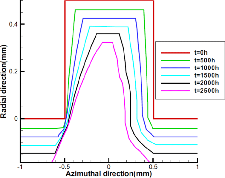
Erosion evolution process for 2500 h of operation (the initial structure is rectangular; erosion moves the wall boundary from top to bottom.)

The simulated erosion evolution process for 2500 h of operation is shown in figure 5. The ceramic walls between two grooves are simulated. The initial rectangle erosion profile is considered. It is found that the rectangular profile is not a stable erosion structure. The erosion rate is not the same in these two lateral walls due to the different bombardment energies and angles. As time goes on, the rectangular groove gradually evolves into a scratch-like structure. At the same time, the two lateral walls are found to have different angles with the horizontal plane. Therefore, asymmetric inclined erosion is formed, which is in accordance with the experimental results.
An increase of axial electron conductivity is also found when considering the anomalous erosion. This result is in accordance with the conclusions of Ahedo & Escobar (Reference Ahedo and Escobar2013). As the azimuthal electric field is formed due to the electron drift, a new axial drift would form with the orthogonal radial magnetic field and azimuthal electric field to make the electrons transverse across the magnetic field and move towards the anode. Our simulated results show that the axial electron conductivity increases twice after considering the anomalous erosion structure and electron Hall drift. Since the electron conductivity has a great influence on the electric potential distribution, the anomalous erosion will influence the thruster performance correspondingly. Therefore, the interaction between anomalous erosion and axial ion flow should also be studied in future works.
4 Conclusions
In summary, the present numerical results have shown that azimuthal electron Hall drift has strong effects on the azimuthal sheath and anomalous erosion structure. An azimuthal electric field will be formed due to the asymmetric characteristics. The electron Hall drift would result in asymmetry of the sheath and anomalous erosion profile. The azimuthal plasma oscillation induced by electron drift has also been validated in the article. It should be the main mechanism for anomalous erosion. Further work for us will include analysing the periodical structure of the anomalous erosion. The results can also be used in other Hall discharge systems such as magnetrons, plasma immersion ion implantations etc.
Acknowledgement
Project supported by the National Natural Science Foundation of China (Grant 11505041 and 51776047).