I. INTRODUCTION
Global energy crisis and environmental pollution are two challenges the world faces. By far, constructing solar–hydrogen energy systems with semiconductor photocatalysts has been proved a promising technology among the solution options. Reference Chen, Shen, Guo and Mao1,Reference Shen, Shi, Guo and Guo2 To date, many kinds of semiconductors have been explored for photocatalytic hydrogen production. They are mainly inorganic semiconductors, such as oxides, Reference Shi and Guo3,Reference Osterloh4 (oxy)sulfides, Reference Zhang5 and (oxy)nitrides. Reference Maeda and Domen6 However, materials with efficient activity and adequate stability for water splitting under visible light irradiation are still unavailable, and their development remains a significant challenge.
In recent years, a novel metal-free polymer semiconductor, graphitic carbon nitride (g-C3N4) with band gap of about 2.7 eV, has showed promising performance for hydrogen production under visible light irradiation. Reference Wang, Maeda, Thomas, Takanabe, Xin, Carlsson, Domen and Antonietti7 However, the photocatalytic efficiency of pure g-C3N4 was relatively low mainly due to the fast recombination of photogenerated electron–hole pairs. Reference Wang, Blechert and Antonietti8 To solve this problem, one strategy is to form heterojunction with matched band structure of the two components (type II band alignment) to separate the photo charge carriers. Reference Wang, Bai, Pan, He and Zhu9–Reference Zhang, Zhang, Sun and Wang18 Another strategy is to load noble metals Reference Di, Wang, Thomas and Antonietti19,Reference Maeda, Wang, Nishihara, Lu, Antonietti and Domen20 such as Au, Pt on g-C3N4 to trap and store the photogenerated electrons.
Since the representative demonstration of plasmonic photocatalysis with plasmonic nanostructures of noble metals (mainly silver and gold), Reference Wang, Huang, Qin, Zhang, Dai, Wei and Whangbo21–Reference Zhang, Lima, Lee, Zaera, Chi and Yin23 it has been widely investigated in the field of photocatalytic water splitting. Awazu et al. Reference Awazu, Fujimaki, Rockstuhl, Tominaga, Murakami, Ohki, Yoshida and Watanabe24 embedded silver nanoparticles (Ag NPs) in TiO2, achieving enhanced photocatalytic activity that is confirmed exclusively due to the localized surface plasmon resonance (LSPR) induced electric field amplitude on the surface of Ag NPs. The electric field would consequently induce the plasmon resonance energy transfer (PRET) process, shortening the carriers transfer distance to the surface reactive sites by promoting the electron–hole pairs formation on the surface rather than in the bulk phase of the substrate semiconductor. The key for fabrication of the building blocks was that the Ag NPs must be coated with an SiO2 shell to prevent oxidation by TiO2. Ingram and Linic Reference Ingram and Linic25 also used Ag NPs to create Ag/N-TiO2 composite plasmonic photocatalysts with improved water splitting performance. They found that a nonconductive shell between Ag NPs and N-TiO2 greatly affected the charge carriers transfer process by inhibiting the nonradiative energy loss process from N-TiO2 to Ag NPs, namely, the Förster resonance energy transfer (FRET) effect; on the contrary, energy could efficiently transfer from the plasmonic Ag NPs to N-TiO2 surface via the PRET process, increasing the carriers concentration on the surface of N-TiO2.
In the present study, Ag NP-modified g-C3N4 was developed to investigate the plasmonic effect of Ag NPs on photocatalytic hydrogen evolution under visible light. To improve the stability Reference Awazu, Fujimaki, Rockstuhl, Tominaga, Murakami, Ohki, Yoshida and Watanabe24 and activity Reference Ingram and Linic25 of the Ag NPs, Ag NPs coated with a thin nonconductive silica shell, namely Ag@SiO2, were further prepared to modify g-C3N4. It was found that modified with Ag@SiO2 NPs, g-C3N4 achieved a better photocatalytic hydrogen production activity than with Ag NPs. The effect of the Ag and Ag@SiO2 NPs on visible light photocatalytic activity of g-C3N4 was studied and a possible mechanism was proposed.
II. EXPERIMENTAL DETAILS
A. Preparation of the Ag/g-C3N4, Ag@SiO2/g-C3N4 composite photocatalysts
Analytical-grade silver nitrate (AgNO3), ethylene glycol (HOCH2CH2OH), polyvinylpyrrolidone (PVP, K-30, M w ≈ 40,000), melamine, ammonium hydroxide (NH4OH, 25% NH3 in H2O), acetone, ethanol, and tetraethylorthosilicate (TEOS) were purchased from Sinopharm Chemical Reagent Co., Ltd. (Beijing, China) and used without further purification. Analytical-grade H2PtCl6·6H2O was purchased from Alfa Aesar Co. Ltd. (Tianjin, China) and dissolved in distilled H2O for further use.
1. Synthesis of Ag and Ag@SiO2 NPs
Ag NPs were synthesized by a reported polyol process with minor modification. Reference Silvert, Herrera-Urbina and Tekaia-Elhsissen26,Reference Gao, Jelle and Gustavsen27 Typically, 10 g PVP was added into 75 mL ethylene glycol in a 200 mL glass beaker under stirring at 393 K oil bath. After the PVP was totally dissolved, 400 mg AgNO3 was added to the solution and then maintained at this temperature for 1 h. The produced Ag NPs were separated by centrifugation (10,000 rpm for 60 min) and washed twice with acetone and ethanol, respectively. The obtained Ag NPs were dispersed in ethanol to form a colloid solution with the concentration of about 17.46 mg/mL.
Core–shell Ag@SiO2 NPs were synthesized by a modulated sol–gel process. Reference Kim, Jeong and Moon28,Reference Graf, Vossen, Imhof and van Blaaderen29 For a typical synthesis, 5 g PVP was dissolved in 50 mL water under vigorous stirring, and 4 mL of the as-prepared Ag NPs colloidal solution was added to this solution. After stirring at 500 rpm for 1 h, the PVP-modified Ag NPs were separated from the solution by centrifugation (10,000 rpm for 60 min) and then redispersed into 50 mL of an ammonia–ethanol solution (5 vol% NH4OH in ethanol). Then 15 μL of TEOS–ethanol solution (20 vol% TEOS in ethanol) was added and stirred at 500 rpm for 2 h. The solid product was separated from the mother solution by centrifugation (10,000 rpm for 60 min). The obtained sediments of core–shell Ag@SiO2 NPs were redispersed in ethanol to form a colloidal solution (concentration ≈ 16.46 mg/mL) for further use.
2. Synthesis of g-C3N4, Ag- or Ag@SiO2-modified g-C3N4
g-C3N4 was synthesized by a pyrolysis method. Reference Wang, Maeda, Thomas, Takanabe, Xin, Carlsson, Domen and Antonietti7 Typically, 3 g melamine was dissolved in 150 mL distilled water under vigorous stirring at 363 K. Then the temperature was elevated to 373 K to evaporate the solution. The resulting mixture was put into an alumina crucible with a cover and heated to 793 K with a ramping rate of 20 K/min and kept at that temperature for 4 h. The resulting materials were then grounded into powder for further characterization.
g-C3N4 modified with Ag or Ag@SiO2 were prepared by adding colloidal solution of Ag or Ag@SiO2 into the precursor solution for synthesis of pure g-C3N4. Typically, colloidal solution with 80 mg of Ag or Ag@SiO2 was added to the melamine solution and kept at 363 K for 1 h under stirring. Then the temperature was elevated to 373 K to evaporate the solution. The resulting mixture was collected and annealed in the same way as the pure g-C3N4.
B. Characterization
The transmission electron microscopy (TEM) images were obtained from an FEI Tecnai G2 F30 S-Twin transmission electron microscope (Oregon) at an accelerating voltage of 300 KV. The x-ray diffraction (XRD) patterns were obtained from a PANalytical X’pert MPD Pro diffractometer (Netherlands) operated at 40 KV and 40 mA using Ni-filtered Cu Kα irradiation (wave length 1.5406 Å). UV-vis absorption spectra (UV-vis) were measured on a HITACHI U4100 instrument (Tokyo, Japan) equipped with labsphere diffuse reflectance accessory using BaSO4 as the reference. The analysis of photoluminescence spectra (PL, including PL emission and PL decay) was carried out at room temperature using a PTIQM-4 fluorescence spectrophotometer (Tokyo, Japan). In detail, PL emission spectra were obtained at 337 nm, the PL decay spectra were observed at 470 nm, and the excitation wave length was obtained at 337 nm.
C. Evaluation of photocatalytic activity
Photocatalytic hydrogen evolution was performed in a gas-closed circulation system with an approximate 230 mL top window Pyrex cell as the photoreactor. A 300 W Xe lamp was used as the light source, and the UV part of the light was removed by a cutoff filter (λ > 420 nm). Hydrogen evolved was analyzed on a thermal conductivity detector gas chromatograph (NaX zeolite column, nitrogen as a carrier gas) every 60 min. In a typical experiment, the photocatalyst powder (0.1 g) was dispersed by a magnetic stirrer in 180 mL of 10 vol% triethanolamine (TEOA) aqueous solution. The cocatalyst Pt (1 wt%) was photodeposited in situ on the photocatalysts from the precursor of H2PtCl6·6H2O. Nitrogen was purged through the cell for 20 min before reaction to remove oxygen. The temperature for all the photocatalytic reactions was kept at 35 ± 0.5 °C by thermostatic waterbath.
III. RESULTS AND DISCUSSION
A. Morphology
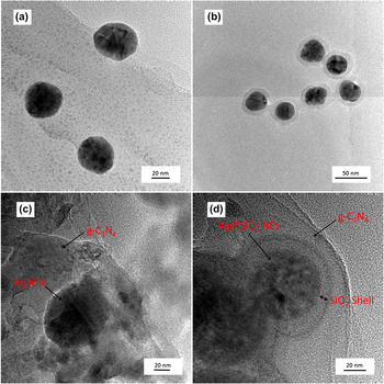
TEM images were taken to investigate the morphology of the Ag and Ag@SiO2 NPs and the modified g-C3N4 photocatalysts. Figs. 1(a) and 1(b) show the TEM images of Ag and Ag@SiO2 NPs. The NPs are nearly spherical in shape with diameter of approximately 35 nm. The relatively small particle size will favor the PRET process instead of scattering effects, which is more possible to occur with 100 nm NPs. Reference Warren and Thimsen30 After coated with silica, core–shell Ag@SiO2 NPs were formed, as shown in Fig. 1(b). The silica shell is about 7–9 nm in thickness and uniformly covers the Ag NPs. As for the Ag NP-modified g-C3N4 sample, close contact could be seen between Ag and g-C3N4 in Fig. 1(c), while in Fig. 1(d), a silica shell was there between the Ag NPs and the g-C3N4, preventing them from direct contact. As reported, Reference Warren and Thimsen30 the nonconductive silica shell could prevent the hot electrons injection from the metals to the semiconductor and the hole-drift process from the semiconductor to the metals. The effects of SiO2 shell on plasmonic photocatalysis will be discussed in the following sections.
TEM images of (a) Ag nanoparticles, (b) Ag@SiO2 nanoparticles, (c) Ag/g-C3N4, and (d) Ag@SiO2/g-C3N4.

B. XRD analysis
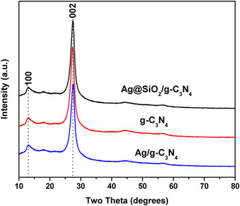
Figure 2 displays the XRD patterns for g-C3N4 and Ag- or Ag@SiO2-modified g-C3N4. The XRD patterns of all the samples present quite similar profiles and the diffraction peaks can be attributed to the graphitic phase with tri-s-triazine unit in its structure. Reference Wang, Maeda, Thomas, Takanabe, Xin, Carlsson, Domen and Antonietti7 The unchanged peak position and shape indicates that the g-C3N4 structure did not change with Ag or Ag@SiO2 modification. However, no Ag or Ag@SiO2 peaks were detected from the XRD patterns mainly because the NPs in those samples are well dispersed and the NP contents are too low. Reference Xu, Liu, Ren, Zhang, Wang, Guo, Guo and Lu31,Reference Zhao, Lin, Jin, Dai and Wang32
XRD patterns of Ag@SiO2/g-C3N4, Ag/g-C3N4, and g-C3N4.

C. Optical properties
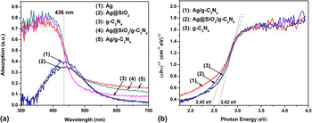
Figure 3(a) shows the UV-vis absorption spectra of the as-prepared photocatalysts. The absorption edge of the pure g-C3N4 was about 470 nm, corresponding to a band gap of 2.62 eV. The absorption band of Ag and Ag@SiO2 was centered at 436 nm due to the excitation of surface plasmon oscillations in the Ag NPs Reference Wiley, Im, Li, McLellan, Siekkinen and Xia33 and is consistent with the LSPR frequency of Ag NPs. After modulation, the visible light absorption ability of g-C3N4 was enhanced, and the band gap was improved from 2.62 to 2.43 eV as calculated from tauc plot [Fig. 3(b)]. As seen from Fig. 3(a), the absorption of Ag and Ag@SiO2 in the range of 420–700 nm is overlapped with that of g-C3N4, which would explain the absorption improvement for the ameliorated photocatalysts. The overlap of absorption spectrum could offer enough energy to overcome the band gap of the substrate semiconductor via the PRET process. Reference Warren and Thimsen30,Reference Linic, Christopher and Ingram34
(a) UV-vis absorption spectra of (1) Ag, (2) Ag@SiO2, (3) g-C3N4 and the modified photocatalysts, (4) Ag@SiO2/g-C3N4, (5) Ag/g-C3N4 and (b) tauc plot for g-C3N4 and the modified samples.

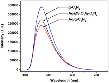
Figure 4 shows the PL spectra for the as-prepared photocatalysts excited at 337 nm. As seen from Fig. 4, the photocatalysts exhibit a broad emission peak centered at around 470 nm, corresponding to the band gap of g-C3N4. The emission could be attributed to the band-band PL phenomenon of the photoinduced charge carriers for g-C3N4. Reference Wang, Blechert and Antonietti8,Reference Yan, Lv, Li and Zou17 The PL emission intensity reaches its maximum with the pure g-C3N4 and decreases with Ag or Ag@SiO2 modification.
Photoluminescence emission spectra of g-C3N4, Ag@SiO2/g-C3N4, and Ag/g-C3N4 excited at 337 nm obtained at room temperature.

In a plasmonic photocatalyst, charge carriers transfer process was mainly influenced by PRET and FRET effects. Reference Kim, Jeong and Moon28,Reference Zhao, Lin, Jin, Dai and Wang32 PRET induces an energy transfer process from plasmonic metals to the substrate semiconductor, promoting formation of charge-carriers on the surface of the semiconductor, which shortened the minority carriers transfer distance to the semiconductor’s surface reactive sites, thus inhibiting the charge carrier recombination. On the contrary, FRET is an energy transfer process from the substrate semiconductor to plasmonic metals, quenching the semiconductor excited state in a nonradiative way, which lessens the electrons for recombination and photocatalytic reaction.
It is reasonable to deduce that the PL quenching of g-C3N4 with Ag@SiO2 or Ag NPs modification is due to PRET and FRET effects. The electric field induced from the LSPR effect near the Ag NPs favors the PRET process, which decreased the PL intensity via suppressing the charge carrier recombination by shortening the minority carriers transfer distance. FRET lowered the PL intensity by depleting the excited state in the semiconductor. Both these two effects are strong functions of distance from the metal NPs to the surface of the substrate semiconductor. Thus, the smaller PL intensity of Ag/g-C3N4 than that of Ag@SiO2/g-C3N4 could be understood by the stronger PRET and FRET effects caused by the shorter distance of Ag NPs and g-C3N4 in Ag/g-C3N4.
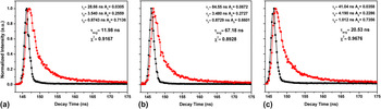
To further confirm our hypothesis, fluorescence emission decay spectra were taken to measure the carrier lifetimes. Figure 5 shows the fluorescence emission decay curves for the as-prepared photocatalysts at room temperature. These emission signals were analyzed using tri-exponential decay kinetics Reference Niu, Zhang, Liu and Cheng35,Reference Barman and Sadhukhan36 instead of bi-exponential kinetics for the value of the goodness-of-fit parameter (χ2) was closer to 1 calculated from the former, which indicated a better fit of the data. Reference Lakowicz37 The kinetic parameters for these photocatalysts are summarized in Fig. 5. Equation (1) was applied to carry out the tri-exponential kinetic analysis; Eq. (2) (Ref. Reference Lakowicz37) was used to calculate average lifetime τavg.
 $$y = \sum {{a_i}} {{\rm{e}}^{ - \left( {{\textstyle{t \over {{{\rm{\tau }}_i}}}}} \right)}}\quad ,$$
 $${{\rm{\tau }}_{{\rm{avg}}}} = {{\sum {{a_i}{\rm{\tau }}_i^2} } \over {\sum {{a_i}{{\rm{\tau }}_i}} }}\quad .$$
Fluorescence emission decay curves for (a) g-C3N4, (b) Ag/g-C3N4, (c) Ag@SiO2/g-C3N4 at room temperature. Observation wave length for all the samples was at 470 nm, and the excitation wave length was at 337 nm (●) decay curve, (■) instrument response function curve. Solid lines represent the kinetic fit using tri-exponential decay analysis.

The average lifetimes of the carriers (τavg) are 11.98, 20.53, and 67.18 ns for g-C3N4, Ag@SiO2/g-C3N4, and Ag/g-C3N4, respectively. Obviously, the decay time for g-C3N4 was prolonged with Ag or Ag@SiO2 modification, and for Ag/g-C3N4, it was longer than that of Ag@SiO2/g-C3N4. The prolongation of decay time indicates more efficient charge carriers separation in g-C3N4. Reference Linic, Christopher and Ingram34,Reference Niu, Zhang, Liu and Cheng35 As for Ag@SiO2/g-C3N4, direct charge transfer from g-C3N4 to Ag NPs was prevented by the insulating SiO2 shell; instead, the decay time prolongation could be due to field effect, i.e., PRET, causing efficient charge carrier separation at the near-surface of g-C3N4. As for Ag/g-C3N4, closer contact between the components induced more intense field effect, benefiting more efficient charge carrier separation and resulting in longer decay time than that of Ag@SiO2/g-C3N4. Moreover, charge carrier separation was also favored by direct charge transfer from g-C3N4 to Ag NPs, which may occur in Ag/g-C3N4. Reference Meng, Shen, Chen and Xin38
D. Visible light photocatalytic hydrogen production activity
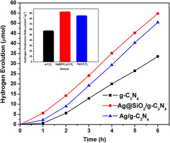
Figure 6 shows the time dependence of photocatalytic H2 evolution from an aqueous TEOA solution over the as-prepared photocatalysts under visible-light irradiation (λ > 420 nm). All the samples are photocatalytically active and stable for hydrogen production. No hydrogen was detected in the absence of photocatalyst or light irradiation. The rate of hydrogen evolution over pure g-C3N4 was 56.02 μmol/h/g, and with Ag NPs modification, the hydrogen evolution rate was increased by approximately 50%. The Ag@SiO2 modified sample showed further increased photocatalytic activity with hydrogen evolution rate increased by approximately 63% when compared with pure g-C3N4. Little hydrogen (10.5 μmol/h/g) was also detected from TEOA solution without Pt as a cocatalyst, while no hydrogen was produced from pure water even with Pt.
Photocatalytic H2 evolution under visible-light irradiation over the as-prepared samples.

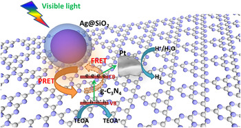
The possible mechanism for photocatalysis is illustrated in Fig. 7. The plasmonic effects of metal NPs, i.e., the PRET and FRET effect are known to depend on the distance between metal (Ag) NPs and semiconductor substrate (g-C3N4). As revealed by PL analysis in Figs. 4 and 5, separation of charge carriers was inhibited both in Ag/g-C3N4 and Ag@SiO2/g-C3N4, thus resulted in an enhanced photocatalytic hydrogen production activity compared with pure g-C3N4. Ag@SiO2/g-C3N4 exhibited better activity than Ag/g-C3N4, although the latter showed more efficient charge separation by field effect and possible direct charge transfer process. This may due to the nonradiative energy loss process (i.e., FRET effect) efficiently suppressed by the insulating silica shell in Ag@SiO2/g-C3N4. As the FRET effect is a strong function of distance, the silica shell in Ag@SiO2/g-C3N4 between the Ag NPs and g-C3N4 will increase the distance of the two components, thus reducing the intensity of FRET effect, saving more electrons for hydrogen production. Thus, although may not the optimal, the photocatalytic activity of g-C3N4 was improved by Ag@SiO2 core–shell structure with the 7–9 nm silica shell, when compared with Ag/g-C3N4 as well as pure g-C3N4. The photocatalytic mechanism for plasmonic Ag@SiO2-modified g-C3N4 may be more complicated and further research on the effects of Ag morphology and SiO2 shell thickness on plasmonic photocatalysis are under investigation in our group.
Photocatalytic mechanism for H2 evolution over Ag@SiO2/g-C3N4 under visible light.

IV. CONCLUSION
We have demonstrated that plasmonic Ag NPs and Ag@SiO2 core–shell NPs can be used to create composite plasmonic-metal/g-C3N4 photoelectrocatalysts that exhibit enhanced water splitting performance relative to the bulk g-C3N4 alone. The photoactivity enhancement can be attributed to the PRET process induced from the LSP effect of Ag NPs and Ag@SiO2 core–shell NPs, which increased the rate formation and retard the recombination of electron–hole pairs at the nearby g-C3N4 surface. Ag@SiO2/g-C3N4 showed more enhanced photocatalytic activity than Ag/g-C3N4 due to the inhibition of FRET process by separating Ag NPs and g-C3N4 using silica shell. The possible explanation was proposed to be a competition mechanism between the PRET and FRET process. The key to get better photocatalytic activity with plasmonic metal NPs modification might be to control the space between the NPs and the semiconductor substrate, achieving largely inhibition of the FRET process with little deactivation of the PRET process.
ACKNOWLEDGMENTS
The authors gratefully acknowledge the financial supports from the National Natural Science Foundation of China (Grant Nos. 51102194 and 51121092) and National Basic Research Program of China (Grant No. 2009CB220000).