1 Introduction
Turbulent suspensions of tiny particles with aspherical shapes are commonly occurring in nature and industry, such as plankton in oceanic flows (Guasto, Rusconi & Stocker Reference Guasto, Rusconi and Stocker2012) and pulp fibre suspensions in paper-making processes (Lundell, Söderberg & Alfredsson Reference Lundell, Söderberg and Alfredsson2011). Shape is known to affect the sinking rate of plankton and their eventual deposition in homogeneous isotropic turbulence (HIT). Since turbulence is a controlling factor (Ruiz, Macas & Peters Reference Ruiz, Macas and Peters2004), it is likely that deposition and aggregation of planktons in sheared turbulence will be different than in HIT and consequently affect the net vertical flux of carbon in the ocean and thus the aquatic ecosystem. Whether pulp fibres orient randomly or align preferentially in the headbox of a paper machine has crucial impact on the quality of the final paper (Carlsson, Söderberg & Lundell Reference Carlsson, Söderberg and Lundell2010). A better understanding of the subtle mechanisms that determine the orientations of non-spherical particles is therefore beneficial in these rather disparate fields of science and engineering.
In recent years rotation of spheroidal particles in homogeneous isotropic turbulence has been actively investigated (Parsa et al. Reference Parsa, Calzavarini, Toschi and Voth2012; Gustavsson, Einarsson & Mehlig Reference Gustavsson, Einarsson and Mehlig2014; Marcus et al. Reference Marcus, Parsa, Kramel, Ni and Voth2014; Byron et al. Reference Byron, Einarsson, Gustavsson, Voth, Mehlig and Variano2015). It is reported that disk-like particles generally ‘tumble’ and rod-like particles ‘spin’. These interesting rotational behaviours have been explained by examining the alignment of the spheroids with the local vorticity vector. The long rod-like particles were found to align their symmetry axis in the direction of the fluid vorticity (Parsa et al. Reference Parsa, Calzavarini, Toschi and Voth2012; Marcus et al. Reference Marcus, Parsa, Kramel, Ni and Voth2014; Ni, Ouellette & Voth Reference Ni, Ouellette and Voth2014), whereas the symmetry axis of thin disk-like particles tended to align normal to the vorticity vector (Marcus et al. Reference Marcus, Parsa, Kramel, Ni and Voth2014; Byron et al. Reference Byron, Einarsson, Gustavsson, Voth, Mehlig and Variano2015). Such qualitatively different alignments of rods and disks relative to the local fluid vorticity inevitably cause different modes of rotation. Ni et al. (Reference Ni, Ouellette and Voth2014, Reference Ni, Kramel, Ouellette and Voth2015) showed that both the fluid vorticity vector and the symmetry axis of long rods were independently aligned in the direction of the strongest Lagrangian fluid stretching (the extensional Cauchy–Green eigenvector). They could thereby explain the earlier observed preferential alignment of long rods with the fluid vorticity. Very recently, Hunt et al. (Reference Hunt, Tierney, Kramel and Voth2015) demonstrated that disk-like particles oriented themselves with their symmetry axis perpendicular to the vorticity and preferentially aligned with the compressional Cauchy–Green eigenvector.
In anisotropic near-wall turbulence, highly elongated particles with modest inertia have been observed to orient preferentially relative to the mean-flow direction both in laboratory experiments (Carlsson et al. Reference Carlsson, Söderberg and Lundell2010; Abbasi Hoseini, Lundell & Andersson Reference Abbasi Hoseini, Lundell and Andersson2015; Capone & Romano Reference Capone and Romano2015) and in numerical simulations (Zhang et al. Reference Zhang, Ahmadi, Fan and Mclaughlin2001; Mortensen et al. Reference Mortensen, Andersson, Gillissen and Boersma2008a ,Reference Mortensen, Andersson, Gillissen and Boersma b ; Marchioli, Fantoni & Soldati Reference Marchioli, Fantoni and Soldati2010; Zhao, Andersson & Gillissen Reference Zhao, Andersson and Gillissen2013; Marchioli, Zhao & Andersson Reference Marchioli, Zhao and Andersson2016). Challabotla, Zhao & Andersson (Reference Challabotla, Zhao and Andersson2015a ) explored the rotation and orientation of inertial disk-shaped particles in channel-flow turbulence and subsequently investigated the behaviour of inertia-free disks and rods in turbulent channel flow (Challabotla, Zhao & Andersson Reference Challabotla, Zhao and Andersson2015b ).
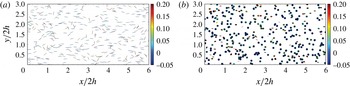
Inertia-free spheroids translate passively along with the local fluid motion irrespective of the particle shape. The tracer particles do therefore not concentrate preferentially, as observed by the evenly distributed spheroids in figure 1. This is in contrast to the preferential concentration of prolate (Mortensen et al.
Reference Mortensen, Andersson, Gillissen and Boersma2008b
; Zhao, Marchioli & Andersson Reference Zhao, Marchioli and Andersson2014) and oblate (Challabotla et al.
Reference Challabotla, Zhao and Andersson2015a
) spheroids with inertia. Nevertheless, a distinct preferential orientation of long rods and thin disks is evident in the buffer layer. The long rods in figure 1(a) tend to align with their symmetry (major) axis in the streamwise direction, in accordance with the recent laboratory experiments by Carlsson et al. (Reference Carlsson, Söderberg and Lundell2010), Abbasi Hoseini et al. (Reference Abbasi Hoseini, Lundell and Andersson2015) and Capone & Romano (Reference Capone and Romano2015) and computer simulations by Mortensen et al. (Reference Mortensen, Andersson, Gillissen and Boersma2008a
,Reference Mortensen, Andersson, Gillissen and Boersma
b
), Marchioli et al. (Reference Marchioli, Fantoni and Soldati2010) and Zhao et al. (Reference Zhao, Andersson and Gillissen2013) focussed on the orientation of rod-like particles or fibres with modest inertia. Thin disks, on the contrary, align with their symmetry (minor) axis perpendicular to the channel wall, in keeping with very recent simulations of inertia-free disks reported by Challabotla et al. (Reference Challabotla, Zhao and Andersson2015b
) and Zhao et al. (Reference Zhao, Challabotla, Andersson and Variano2015). The colour coding of the individual spheroids reflects their rate of rotation about the spanwise
 $y$
-axis and it is noteworthy that spanwise angular velocity is substantially lower than the rotation rate of a spherical tracer. Challabotla et al. (Reference Challabotla, Zhao and Andersson2015b
) showed that the mean angular velocity in spanwise direction in the near-wall region decreased monotonically with increasing asphericity, i.e. for increasing departure from spherical shape. Challabotla et al. (Reference Challabotla, Zhao and Andersson2015b
) argued that the rotation of tracer spheroids in near-wall turbulence follows Jeffery orbits similarly as in a linear shear flow. The low particle rotation rates reported were ascribed to the preferential alignment of rods in the flow direction and disks in the wall-normal direction.
Instantaneous distribution of tracer spheroids in the buffer layer
 $z^{+}\approx 10$
at the lower channel wall. The spheroidal particles are projected into the wall-parallel (
 $x,y$
)-plane and the shape of their projections reflects the particle orientation. The particle colour encodes their spanwise angular velocity
 $\unicode[STIX]{x1D714}_{y}$
. Recall that the mean spanwise fluid angular velocity
 $\langle \unicode[STIX]{x1D6FA}_{y}\rangle =(1/2)\,\text{d}\langle U\rangle /\text{d}z$
reaches its maximum value 0.5 at the wall. (a) Rod-like spheroids with
 $\unicode[STIX]{x1D706}=50$
; (b) disk-like spheroids with
 $\unicode[STIX]{x1D706}=0.01$
.
 $\unicode[STIX]{x1D706}$
is the aspect ratio defined as the ratio
 $2b/2a$
between the length of the symmetry axis and the two equal axes.

However, in spite of the many consistent observations of preferential orientation of aspherical particles in wall turbulence, the underlying mechanism has not yet been uncovered. Zhao et al. (Reference Zhao, Challabotla, Andersson and Variano2015) examined the alignment of inertial and tracer spheroids with respect to the vorticity vector in the near-wall region in a turbulent channel flow and hypothesized that such preferential alignments might be caused by Lagrangian coherent structures (LCSs), which crucially affect particle transport and mixing (Haller Reference Haller2015). Near-wall LCSs have been studied in channel-flow turbulence in recent years, for instance by Green, Rowley & Haller (Reference Green, Rowley and Haller2007), Yang & Pullin (Reference Yang and Pullin2011) and Bettencourt, López & Hernández-García (Reference Bettencourt, López and Hernández-García2013). The eigenvalues of the Cauchy–Green strain tensor are used to identify the LCSs (Haller Reference Haller2015) and the direction of the Lagrangian stretching can be obtained from the eigenvectors of the left Cauchy–Green strain tensor (Parsa et al. Reference Parsa, Guasto, Kishore, Ouellette, Gollub and Voth2011; Ni et al. Reference Ni, Ouellette and Voth2014). To the present authors’ best knowledge, Lagrangian stretching experienced by fluid elements and spheroidal particles in channel-flow turbulence has so far not been investigated.
Some questions regarding the orientational dynamics of light non-spherical particles in wall turbulence emerge in the wake of the aforementioned studies: could it be that the frequently observed preferential particle orientation in anisotropic near-wall turbulence is caused by the alignment relative to the direction of strongest Lagrangian stretching (compression), similarly to the alignment in homogeneous isotropic turbulence? In order to answer that question, one first has to ask: what is the strongest Lagrangian stretching (compression) direction in near-wall turbulence? And, finally, does the fluid vorticity vector also align in the direction of the strongest Lagrangian stretching in anisotropic wall turbulence, as already observed by Ni et al. (Reference Ni, Ouellette and Voth2014, Reference Ni, Kramel, Ouellette and Voth2015) in HIT? In this article we address the above questions by looking into dilute suspensions of differently shaped tracer spheroids in channel-flow turbulence with a view to analyse the alignment of both the spheroids and the fluid vorticity vector relative to direction of the Lagrangian stretching.
2 Mathematical modelling and computational approach
An Eulerian–Lagrangian approach is adopted to simulate tracer spheroids suspended in channel-flow turbulence. The motion of the incompressible fluid is governed by the Navier–Stokes equations and constrained by mass conservation. We consider axisymmetric ellipsoids, i.e. spheroids, with aspect ratio
 $\unicode[STIX]{x1D706}$
defined as the ratio
 $2b/2a$
between the length of the symmetry axis and the two equal axes. The inertia-free spheroidal point particles are suspended in the continuous fluid flow similarly to our earlier studies (Mortensen et al.
Reference Mortensen, Andersson, Gillissen and Boersma2008a
,Reference Mortensen, Andersson, Gillissen and Boersma
b
; Challabotla et al.
Reference Challabotla, Zhao and Andersson2015a
; Zhao et al.
Reference Zhao, Challabotla, Andersson and Variano2015). In absence of inertia however, the spheroids translate along with the local fluid flow while they rotate such that the Jeffery-torques (Jeffery Reference Jeffery1922) vanish exactly, i.e.
 $$\begin{eqnarray}\left.\begin{array}{@{}c@{}}\unicode[STIX]{x1D714}_{x}^{\prime }=-\unicode[STIX]{x1D6EC}\unicode[STIX]{x1D61A}_{yz}^{\prime }+\unicode[STIX]{x1D6FA}_{x}^{\prime },\\ \unicode[STIX]{x1D714}_{y}^{\prime }=\unicode[STIX]{x1D6EC}\unicode[STIX]{x1D61A}_{xz}^{\prime }+\unicode[STIX]{x1D6FA}_{y}^{\prime },\\ \unicode[STIX]{x1D714}_{z}^{\prime }=\unicode[STIX]{x1D6FA}_{z}^{\prime }.\end{array}\right\}\end{eqnarray}$$
This set of equations demonstrates the coupling between the particle rotation vector
 $\unicode[STIX]{x1D714}_{i}^{\prime }$
, the fluid rotation vector
 $\unicode[STIX]{x1D6FA}_{i}^{\prime }$
and the fluid strain-rate tensor
 $\unicode[STIX]{x1D61A}_{ij}^{\prime }$
in the particle frame of reference
 $x_{i}^{\prime }=\langle x^{\prime },y^{\prime },z^{\prime }\rangle$
with origin at the particle centre of mass and coordinate axes aligned with the three principal directions of inertia. The shape parameter
 $\unicode[STIX]{x1D6EC}\equiv (\unicode[STIX]{x1D706}^{2}-1)/(\unicode[STIX]{x1D706}^{2}+1)$
is a measure of the degree of asphericity. Moreover,
 $\unicode[STIX]{x1D6EC}$
is positive for prolate spheroids (
 $\unicode[STIX]{x1D706}>1$
) and negative for oblate spheroids (
 $\unicode[STIX]{x1D706}<1$
).
A turbulent channel flow was realized in a direct numerical simulation (DNS). The governing equations were integrated in time by means of an explicit second-order Adams–Bashforth scheme whereas a pseudo-spectral method was used in the two homogeneous directions and second-order finite-difference discretization in the wall-normal (
 $z$
) direction (see e.g. Mortensen et al.
Reference Mortensen, Andersson, Gillissen and Boersma2008b
). Periodic boundary conditions were used in the two homogeneous directions and no-slip and impermeability conditions were imposed at the two parallel channel walls. The frictional Reynolds number
 $Re_{\unicode[STIX]{x1D70F}}$
based on the channel half-height
 $h$
, the friction velocity
 $u_{\unicode[STIX]{x1D70F}}$
and the kinematic viscosity
 $\unicode[STIX]{x1D708}$
was 180. The friction velocity is defined in terms of the wall shear stress
 $\unicode[STIX]{x1D70F}_{w}$
as
 $u_{\unicode[STIX]{x1D70F}}=(\unicode[STIX]{x1D70F}_{w}/\unicode[STIX]{x1D70C})^{1/2}$
where
 $\unicode[STIX]{x1D70F}_{w}$
is proportional with the prescribed driving mean pressure gradient
 $\text{d}P/\text{d}x<0$
. Hereinafter, all variables will be normalized by viscous scales for velocity (
 $u_{\unicode[STIX]{x1D70F}}$
), length (
 $\unicode[STIX]{x1D708}/u_{\unicode[STIX]{x1D70F}}$
) and time (
 $\unicode[STIX]{x1D708}/u_{\unicode[STIX]{x1D70F}}^{2}$
). The size of the computational domain was
 $12h\times 6h\times 2h$
in the streamwise, spanwise and wall-normal directions, respectively, and 192 grid points were used in each direction. The grid resolution in the streamwise and spanwise directions became
 $\unicode[STIX]{x0394}x^{+}=11.3$
and
 $\unicode[STIX]{x0394}y^{+}=5.6$
while the non-uniform grid spacing in the wall-normal direction varied from
 $\unicode[STIX]{x0394}z^{+}=0.9$
next to the walls to 2.86 in the channel centre. The time integration was performed with a constant time step
 $\unicode[STIX]{x0394}t^{+}=0.036$
.
Six different particle shapes
 $\unicode[STIX]{x1D706}=0.01$
, 0.33, 0.8, 1.5, 3 and 50, all with equatorial radius
 $a^{+}=0.36$
, were considered. 500 000 spheroids of each shape were injected arbitrarily into the same turbulence field at
 $t^{+}=0$
when the flow field had evolved into a fully developed channel flow. We assumed that the suspension was sufficiently dilute so that one-way coupled simulations could be justified, i.e. reaction forces from the particles on the local fluid were of negligible importance, and moreover, that particle–particle collisions rarely occurred and could be neglected. To justify the point-particle treatment and the use of the expressions for the Jeffery torques, the particles were smaller than the Kolmogorov length scale. A particle–wall collision occurred when the centre of a spheroid came closer to the wall than the semi-axis
 $a$
. The wall collisions were assumed to be fully elastic so that a spheroid kept both its linear and angular momentum in the two homogeneous directions after a collision. Such collisions were rare and occurred only about five times at each of the walls during one viscous time unit (
 $\unicode[STIX]{x1D708}/u_{\unicode[STIX]{x1D70F}}^{2}$
).
In order to compute the Cauchy–Green strain tensor, we first stored 55 000 Lagrangian trajectories together with the particle orientation vector
 $\boldsymbol{p}$
, the particle rotation vector
 $\unicode[STIX]{x1D74E}$
and local fluid velocity gradient tensor
 $\unicode[STIX]{x1D608}_{ij}$
for each of the six different particle shapes. These data were gathered and saved every
 $\unicode[STIX]{x0394}T=0.72\unicode[STIX]{x1D708}/u_{\unicode[STIX]{x1D70F}}^{2}$
over a total time window
 $T=144\unicode[STIX]{x1D708}/u_{\unicode[STIX]{x1D70F}}^{2}$
, i.e. 200 times. Notice that this choice of
 $\unicode[STIX]{x0394}T^{+}$
is approximately
 $1/3\text{rd}$
of the smallest time scale in the entire flow field whereas the time window
 $T^{+}=144$
for the trajectory integration amounts to 0.8 large-eddy turnover times
 $h/u_{\unicode[STIX]{x1D70F}}$
but exceeds 10 Kolmogorov time units
 $\unicode[STIX]{x1D70F}_{\unicode[STIX]{x1D702}}$
in the channel centre and more than
 $70\unicode[STIX]{x1D70F}_{\unicode[STIX]{x1D702}}$
in the near-wall region. These parameters are comparable with those used by Ni et al. (Reference Ni, Ouellette and Voth2014) who also followed Lagrangian trajectories for
 $O(1)$
large-eddy turnover times. The following procedure, outlined by Parsa et al. (Reference Parsa, Guasto, Kishore, Ouellette, Gollub and Voth2011) and Ni et al. (Reference Ni, Ouellette and Voth2014, Reference Ni, Kramel, Ouellette and Voth2015), was adopted to compute the Cauchy–Greeen tensor. (i) We firstly defined a deformation gradient tensor
 $\unicode[STIX]{x1D60D}_{ij}=\unicode[STIX]{x2202}x_{i}/\unicode[STIX]{x2202}X_{j}$
that characterized the deformation experienced by the fluid element, where
 $X_{j}$
and
 $x_{i}$
were the positions of any point in the fluid element at time
 $t$
and
 $t+\unicode[STIX]{x0394}T$
, respectively. (ii) The time evolution of the deformation gradient tensor was obtained from
 $\text{d}\unicode[STIX]{x1D60D}_{ij}/\text{d}t=\unicode[STIX]{x1D608}_{ik}\unicode[STIX]{x1D60D}_{kj}(t)$
by integrating over
 $\unicode[STIX]{x0394}T$
with initial condition
 $\unicode[STIX]{x1D60D}_{ij}(t_{0})=\unicode[STIX]{x1D6FF}_{ij}$
. Here,
 $\unicode[STIX]{x1D608}_{ij}$
is the local fluid velocity gradient tensor along the Lagrangian trajectory. (iii) Finally, the Lagrangian stretching direction was given by the three eigenvectors
 $\boldsymbol{e}_{L1}$
,
 $\boldsymbol{e}_{L2}$
and
 $\boldsymbol{e}_{L3}$
of the left Cauchy–Green strain tensor
 $\unicode[STIX]{x1D60A}\unicode[STIX]{x1D60E}_{ij}^{L}$
obtained from the deformation gradient tensor
 $\unicode[STIX]{x1D60D}_{ij}$
as
 $\unicode[STIX]{x1D60A}\unicode[STIX]{x1D60E}_{ij}^{L}=\unicode[STIX]{x1D60D}_{ik}\unicode[STIX]{x1D60D}_{jk}$
, see Parsa et al. (Reference Parsa, Guasto, Kishore, Ouellette, Gollub and Voth2011). Since
 $\boldsymbol{e}_{L1}$
is the maximum (extensional) vector and
 $\boldsymbol{e}_{L3}$
is the minimum (compressional) vector, the strongest Lagrangian stretching is in the direction of
 $\boldsymbol{e}_{L1}$
.
3 Results and discussion
3.1 Lagrangian stretching analysis
Ni et al. (Reference Ni, Ouellette and Voth2014) observed that not only prolate spheroids but also the fluid vorticity vector
 $2\unicode[STIX]{x1D734}$
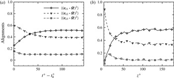
aligned in the direction of Lagrangian stretching in homogenous isotropic turbulence. The crucial question that therefore arises is whether this finding is universally valid, e.g. also in anisotropic channel-flow turbulence in presence of substantial mean vorticity. By considering the alignment of the fluid rotation vector
 $\unicode[STIX]{x1D734}$
relative to the maximum eigenvector of the left Cauchy–Green strain tensor
 $\boldsymbol{e}_{L1}$
in figure 2(a), we can observe that a modest alignment
 $\langle (\boldsymbol{e}_{L1}\boldsymbol{\cdot }\unicode[STIX]{x1D734})^{2}\rangle \approx 0.50$
still exists, although the alignment has attenuated compared with
 $\langle (\boldsymbol{e}_{L1}\boldsymbol{\cdot }\unicode[STIX]{x1D734})^{2}\rangle \approx 0.60$
in homogeneous isotropic turbulence (Ni et al.
Reference Ni, Ouellette and Voth2014). They argued that the stretching of fluid vorticity is the same as the stretching of a material line and tends to align the vorticity in the same direction as
 $\boldsymbol{e}_{L1}$
. They explained the observed plateau
 $\langle (\boldsymbol{e}_{L1}\boldsymbol{\cdot }\unicode[STIX]{x1D734})^{2}\rangle \approx 0.60$
as a result of a dynamic balance between vorticity stretching and viscous effects, the latter which tend to move
 $\unicode[STIX]{x1D734}$
and
 $\boldsymbol{e}_{L1}$
apart. Their conjecture is indeed supported by our results in figure 2(b) which reveal qualitatively different alignments in the near-wall region and at the centre of the channel. Statistics in figure 2(b) is computed by averaging the instantaneous data of alignment between fluid vorticity vector and Lagrangian stretching over the two homogeneous directions (i.e. the streamwise and spanwise) in each of the 100 bins from wall to wall and over the time window from
 $t^{+}=t_{0}^{+}+136$
to
 $t^{+}=t_{0}^{+}+144$
where the correlations of those quantities are in an almost statistically steady state. The fluid vorticity is preferentially aligned with the direction of strongest Lagrangian stretching
 $\boldsymbol{e}_{L1}$
in the nearly isotropic centre region, just as in homogenous isotropic turbulence. Ni et al. (Reference Ni, Ouellette and Voth2014) argued that the vorticity became preferentially aligned with
 $\boldsymbol{e}_{L1}$
simply due to angular momentum conservation. However, this preferred alignment gradually reduces as the wall is approached and tends almost to zero. The vanishing alignment is most pronounced inside of
 $z^{+}<30$
where viscous effects gradually become dominating and, apparently, orient the vorticity perpendicular to
 $\boldsymbol{e}_{L1}$
. The fluid rotation
 $\unicode[STIX]{x1D734}$
, i.e. half of the fluid vorticity, exhibits fundamental differences between the almost isotropic centre region and the near-wall regions. The velocity field in the vicinity of the channel walls is characterized not only by a substantial mean vorticity entirely in the spanwise direction, but also by highly anisotropic vorticity fluctuations (Andersson, Zhao & Variano Reference Andersson, Zhao and Variano2015). The leading component of the instantaneous rotation vector
 $\unicode[STIX]{x1D734}$
is therefore in the
 $y$
-direction and the results in figure 2(b) accordingly show that maximum Lagrangian stretching is in the (
 $x,z$
)-plane.
Alignment of the fluid rotation vector
 $\unicode[STIX]{x1D734}$
relative to the three eigenvectors
 $\boldsymbol{e}_{Li}$
of the left Cauchy–Green strain tensor. (a) Time evolution of
 $\langle (\boldsymbol{e}_{Li}\boldsymbol{\cdot }\unicode[STIX]{x1D734})^{2}\rangle$
; (b) variation of
 $\langle (\boldsymbol{e}_{Li}\boldsymbol{\cdot }\unicode[STIX]{x1D734})^{2}\rangle$
from the wall to the channel centre at
 $z^{+}=180$
sampled in the almost statistically steady state from
 $t^{+}=t_{0}^{+}+136$
to
 $t^{+}=t_{0}^{+}+144$
. Notice that the vorticity vector is two times the rotation vector, i.e.
 $2\unicode[STIX]{x1D734}$
.

The observed alteration in the alignment of the fluid rotation vector
 $\unicode[STIX]{x1D734}$
with the eigenvectors
 $\boldsymbol{e}_{Li}$
of the left Cauchy–Green strain tensor from the channel centre to the channel walls in figure 2(b) could explain the weaker alignment
 $\langle (\boldsymbol{e}_{L1}\boldsymbol{\cdot }\unicode[STIX]{x1D734})^{2}\rangle \approx 0.50$
observed in the channel flow in figure 2(a) as compared with that found in homogenous isotropic turbulence by Ni et al. (Reference Ni, Ouellette and Voth2014). Indeed,
 $\langle (\boldsymbol{e}_{L1}\boldsymbol{\cdot }\unicode[STIX]{x1D734})^{2}\rangle \approx 0.57$
at the centre where the fluid vorticity is almost isotropic.
3.2 Orientation correlations
To uncover the mechanism responsible for the interesting orientational behaviour of inertia-free spheroids in near-wall turbulence, as illustrated in figure 1, we examined the correlation between the particle orientation vector
 $\boldsymbol{p}$
and the three eigenvectors
 $\boldsymbol{e}_{Li}$
of the left Cauchy–Green strain tensor for spheroids with aspect ratios
 $\unicode[STIX]{x1D706}$
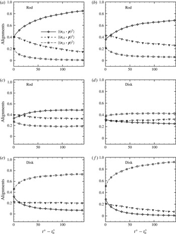
ranging from 50 to 0.01. The statistics shown in figure 3 were obtained by averaging 55 000 Lagrangian particle trajectories over the whole channel. As the elongation of rod-like particles increased to
 $\unicode[STIX]{x1D706}=50$
, their orientation vector
 $\boldsymbol{p}$
approached the direction of strongest Lagrangian stretching
 $\boldsymbol{e}_{L1}$
, similarly to what was observed by Ni et al. (Reference Ni, Ouellette and Voth2014) for prolate spheroids with
 $\unicode[STIX]{x1D706}=20$
suspended in homogeneous isotropic turbulence. This finding suggests that rod-like particles preferentially orient their symmetry axis in the direction of the strongest Lagrangian stretching independently of their actual trajectories in the anisotropic channel flow. While Ni et al. (Reference Ni, Ouellette and Voth2014) reported that the orientation dynamics for rods with aspect ratio larger than approximately 10 was insensitive to aspect ratio, the preferential alignment of the long rods in figure 3(a) was stronger than for the shorter rod-like particles in figure 3(b). By gradually decreasing the aspect ratio to unity (a–c), the alignment gradually attenuates.
Time evolution of the alignment of the orientation vector
 $\boldsymbol{p}$
of spheroidal particles with aspect ratio
 $\unicode[STIX]{x1D706}$
relative to the three eigenvectors
 $\boldsymbol{e}_{Li}$
of the left Cauchy–Green strain tensor. Here,
 $\boldsymbol{e}_{L1}$
and
 $\boldsymbol{e}_{L3}$
are the maximum (extensional) and minimum (compressional) eigenvectors, respectively. The alignment
 $\langle (\boldsymbol{e}_{Li}\boldsymbol{\cdot }\boldsymbol{p})^{2}\rangle$
of two randomly oriented vectors is
 $1/3$
. (a)
 $\unicode[STIX]{x1D706}=50$
, (b)
 $\unicode[STIX]{x1D706}=3$
, (c)
 $\unicode[STIX]{x1D706}=1.5$
, (d)
 $\unicode[STIX]{x1D706}=0.8$
, (e)
 $\unicode[STIX]{x1D706}=0.33$
and (f)
 $\unicode[STIX]{x1D706}=0.01$
.

While the present alignment statistics in figure 3(a) showed striking similarities with the results in figure 1(a) of Ni et al. (Reference Ni, Ouellette and Voth2014), the orientation of disk-like particles with aspect ratios ranging from 0.01 to 0.8 evolved almost oppositely in figure 3(d–f). The oblate spheroids tended to align their symmetry axis perpendicular to the direction of strongest Lagrangian stretching, i.e.
 $\langle (\boldsymbol{e}_{L1}\boldsymbol{\cdot }\boldsymbol{p})^{2}\rangle$
decayed and eventually approached zero for the flattest disks, whereas
 $\boldsymbol{p}$
instead aligned with the minimum eigenvector
 $\boldsymbol{e}_{L3}$
associated with Lagrangian compression. Similar observations for oblate tracer spheroids in homogeneous isotropic turbulence were recently reported by Hunt et al. (Reference Hunt, Tierney, Kramel and Voth2015). When the shape of the spheroid is close to a sphere, as shown in figure 3(c,d), the alignments are approaching to be random but weak preferential alignment still exists.
Initially at
 $t^{+}=0$
, the plots in figure 3 show the instantaneous alignments of the spheroids’ symmetry axis relative to the eigenvectors
 $\boldsymbol{e}_{i}$
of the Eulerian strain-rate tensor. Large aspect ratio rods are more aligned with the eigenvectors
 $\boldsymbol{e}_{1}$
(0.4) and
 $\boldsymbol{e}_{2}$
(0.4) than with the direction of least strain
 $\boldsymbol{e}_{3}$
(0.2). These alignments are slightly different from the observation in HIT by Ni et al. (Reference Ni, Ouellette and Voth2014) where the alignments relative to
 $\boldsymbol{e}_{i}$
(
 $i=1$
, 2, and 3) are 0.4, 0.44 and 0.16, respectively. The modest deviation can be due to the different turbulent flow configurations and Reynolds numbers. As the aspect ratio decreases, the shorter rods preferentially align with
 $\boldsymbol{e}_{2}$
both for
 $\unicode[STIX]{x1D706}=3$
and 1.5. In contrast, disks initially exhibit a preferred alignment with the direction of least shear
 $\boldsymbol{e}_{3}$
and this preference strengthens with increasing flatness of the disks (i.e. as
 $\unicode[STIX]{x1D706}$
decreases). However, much stronger alignments of the spheroids with the eigenvectors
 $\boldsymbol{e}_{Li}$
of left Cauchy–Green tensor can be observed when
 $\boldsymbol{e}_{Li}$
is computed after a time interval
 $t^{+}-t_{0}^{+}$
of the order 100, slightly dependent on the particle’s asphericity
 $\unicode[STIX]{x1D6EC}$
. The Kolmogorov time scale
 $\unicode[STIX]{x1D70F}_{\unicode[STIX]{x1D702}}$
varies from the wall to the centre with a channel-average of approximately
 $8.15\unicode[STIX]{x1D708}/u_{\unicode[STIX]{x1D70F}}^{2}$
at the present Reynolds number. The time interval required for the alignment to saturate therefore amounts to approximately 12
 $\unicode[STIX]{x1D70F}_{\unicode[STIX]{x1D702}}$
, which compares well with
 $t^{+}-t_{0}^{+}\approx 10\unicode[STIX]{x1D70F}_{\unicode[STIX]{x1D702}}$
in HIT (Ni et al.
Reference Ni, Ouellette and Voth2014).
At first sight (2.1) may suggest that fluid rotation and shear contribute equally to the particle rotation for highly aspherical spheroids (
 $|\unicode[STIX]{x1D6EC}|\approx 1$
). However, whereas
 $\unicode[STIX]{x1D74E}^{\prime }$
measures rotation in the particle frame, rotation of inertia-free spheroids can alternatively be expressed by means of the rate of change of the particle orientation unit vector
 $\boldsymbol{p}$
in the inertial frame:
 $$\begin{eqnarray}{\dot{p}}_{i}=\unicode[STIX]{x1D619}_{ij}p_{j}+\unicode[STIX]{x1D6EC}(\unicode[STIX]{x1D61A}_{ij}p_{j}-p_{i}p_{k}\unicode[STIX]{x1D61A}_{kl}p_{l})=\unicode[STIX]{x1D716}_{ijk}\unicode[STIX]{x1D6FA}_{k}p_{j}+\unicode[STIX]{x1D6EC}(\unicode[STIX]{x1D61A}_{ij}p_{j}-p_{i}p_{k}\unicode[STIX]{x1D61A}_{kl}p_{l})\end{eqnarray}$$
see e.g. Leal & Hinch (Reference Leal and Hinch1972), Parsa et al. (Reference Parsa, Calzavarini, Toschi and Voth2012) and Ni et al. (Reference Ni, Kramel, Ouellette and Voth2015). The rotation rate tensor
 $\unicode[STIX]{x1D619}_{ij}$
is related to the fluid rotation vector
 $\unicode[STIX]{x1D6FA}_{i}$
as
 $\unicode[STIX]{x1D619}_{ij}=\unicode[STIX]{x1D716}_{ijk}\unicode[STIX]{x1D6FA}_{k}$
. Here, in contrast to (2.1), all quantities refer to the frame of reference in which the flow field is computed by means of DNS. Now, according to (3.1), the role played by the fluid rotation reduces if the spheroids align themselves along the vorticity vector
 $2\unicode[STIX]{x1D734}$
. This may explain the transition from vorticity-dominated particle rotation for near spheres (
 $\unicode[STIX]{x1D6EC}\approx 0$
) to shear-dominated particle rotation for highly aspherical particles (
 $|\unicode[STIX]{x1D6EC}|\approx 1$
). According to above equation, the rate of change of particle orientation responds immediately to the flow field and particle orientation. However, the particle orientation
 $p_{i}$
does not respond instantaneously to the local flow field but evolves gradually towards alignment with the preferred Lagrangian stretching direction, as seen in figure 3. The actual particle orientation is therefore influenced by the history of the fluid velocity gradients along the Lagrangian trajectory.
The present alignment statistics was gathered along arbitrarily chosen particle trajectories, along which a particle experiences an almost isotropic vorticity field in the channel centre (see Andersson et al.
Reference Andersson, Zhao and Variano2015) but highly anisotropic turbulence near the channel walls. The preferential alignment results in figure 3 are nevertheless strikingly similar with the corresponding results in homogenous isotropic turbulence reported by Ni et al. (Reference Ni, Ouellette and Voth2014, Reference Ni, Kramel, Ouellette and Voth2015) and Hunt et al. (Reference Hunt, Tierney, Kramel and Voth2015). We are therefore inclined to infer that the observed tendency of rods to align with, and disks to orient normal to, the strongest Lagrangian stretching direction
 $\boldsymbol{e}_{L1}$
is robust and universal since the same trends are found in isotropic as well as in highly anisotropic turbulence. The time evolution of these alignment correlations indicates the dependence of the particles’ orientational behaviour on the history of experienced fluid stretching in a Lagrangian view. By revisiting (2.1), the tracer particle rotation in the particle frame only depends on instantaneous local fluid vorticity and strain rate. However, the particle orientation does not respond instantaneously to the local flow field but gradually evolves towards alignment with the preferred Lagrangian stretching direction. This process might cause nearby particles to orient and rotate differently (in the laboratory frame) in spite of almost identical local flow conditions.
After having discovered the major alteration in the alignment
 $\langle (\boldsymbol{e}_{L1}\boldsymbol{\cdot }\unicode[STIX]{x1D734})^{2}\rangle$
(figure 2
b) between the strongest Lagrangian stretching direction
 $\boldsymbol{e}_{L1}$
and the fluid rotation vector
 $\unicode[STIX]{x1D734}$
across the channel, we finally examined how the alignment
 $\langle (\boldsymbol{e}_{L1}\boldsymbol{\cdot }\boldsymbol{p})^{2}\rangle$
between
 $\boldsymbol{e}_{L1}$
and the particle orientation
 $\boldsymbol{p}$
varied with
 $z^{+}$
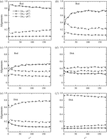
in figure 4. As one could anticipate from the data in figure 3, the major axis of a tracer spheroid with high asphericity
 $|\unicode[STIX]{x1D6EC}|$
is either aligned with
 $\boldsymbol{e}_{L1}$
(long rods with
 $\unicode[STIX]{x1D706}\gg 1$
in figure 4
a) or oriented normal to
 $\boldsymbol{e}_{L1}$
(thin disks with
 $\unicode[STIX]{x1D706}\ll 1$
in figure 4
f). These preferred particle orientations remain almost constant all over the entire channel and confirm the earlier results in figure 3. However, the results in figure 4(b–e) show that the actual particle shape parameterized by the aspect ratio
 $\unicode[STIX]{x1D706}$
also plays an important role. The
 $\unicode[STIX]{x1D706}=3$
spheroids, for instance, were mostly aligned with
 $\boldsymbol{e}_{L1}$
in the centre region, but oriented perpendicular to
 $\boldsymbol{e}_{L1}$
in the vicinity of the channel walls. This changeover of the preferred direction of the orientation vector
 $\boldsymbol{p}$
of the short rods in figure 4(b) corresponds qualitatively with the changeover of the orientation of the fluid rotation vector
 $\unicode[STIX]{x1D734}$
in figure 2(b). With reduced asphericity, as shown in figure 4(c,d), the alignment becomes almost independent of location.
Variation of the alignment of the orientation vector
 $\boldsymbol{p}$
of spheroidal particles with aspect ratio
 $\unicode[STIX]{x1D706}$
relative to the three eigenvectors
 $\boldsymbol{e}_{Li}$
of the left Cauchy–Green strain tensor from the channel wall to the channel centre at
 $z^{+}=180$
sampled in the almost statistically steady state from
 $t^{+}=t_{0}^{+}+136$
to
 $t^{+}=t_{0}^{+}+144$
. The alignment
 $\langle (\boldsymbol{e}_{Li}\boldsymbol{\cdot }\boldsymbol{p})^{2}\rangle$
of two randomly oriented vectors is
 $1/3$
. (a)
 $\unicode[STIX]{x1D706}=50$
, (b)
 $\unicode[STIX]{x1D706}=3$
, (c)
 $\unicode[STIX]{x1D706}=1.5$
, (d)
 $\unicode[STIX]{x1D706}=0.8$
, (e)
 $\unicode[STIX]{x1D706}=0.33$
and (f)
 $\unicode[STIX]{x1D706}=0.01$
.

The apparent alignment between
 $\boldsymbol{p}$
and
 $\unicode[STIX]{x1D734}$
for short rod-like spheroids arose because both vectors independently tended to align with the strongest Lagrangian stretching direction
 $\boldsymbol{e}_{L1}$
in the channel centre. Long rods (flat disks) consistently aligned with (normal to) the strongest Lagrangian stretching direction all across the anisotropic channel flow, similarly as in homogeneous isotropic turbulence. It is noteworthy, however, that the long rods with
 $\unicode[STIX]{x1D706}\gg 1$
preferentially oriented along
 $\boldsymbol{e}_{L1}$
even though the fluid vorticity
 $2\unicode[STIX]{x1D734}$
aligned normal to
 $\boldsymbol{e}_{L1}$
. Challabotla et al. (Reference Challabotla, Zhao and Andersson2015b
) explored the preferential orientation of rod- and disk-like particles in near-wall turbulence. The reduction of particle rotation near the wall with increasing asphericity could be attributed to the strong preferential orientation of rods and disks, which makes the observed rotation in the viscous sublayer qualitatively consistent with spheroids in Jeffery orbits (Jeffery Reference Jeffery1922) in simple shear flow, in which rods (disks) rarely tumble (spin) when they align in streamwise (wall-normal) direction. The reasoning was incomplete, however, due to lack of understanding of why such preferential orientations in either streamwise or wall-normal directions exist. Now the strong alignment of spheroids relative to Lagrangian stretching or compression in the wall region with increasing departure from sphericity is evident in figure 4. This finding, together with previous observations, completes the understanding of orientational and rotational dynamics of tracer spheroids in near-wall turbulence. Furthermore, if triaxial ellipsoids are considered (e.g. Chevillard & Meneveau Reference Chevillard and Meneveau2013), it is likely that the strongest alignment of one of the particle’s principle axes with Lagrangian stretching or compression will determine the orientation and rotation of non-axisymmetric ellipsoids.
From the results in figure 2 we could only infer that the maximum stretching direction
 $\boldsymbol{e}_{L1}$
is in the plane of the mean shear, i.e. the (
 $x,z$
)-plane. Now we have learned from figure 4(a) that the long rods are aligned with
 $\boldsymbol{e}_{L1}$
also in the near-wall region. Since several earlier studies, e.g. Mortensen et al. (Reference Mortensen, Andersson, Gillissen and Boersma2008a
,Reference Mortensen, Andersson, Gillissen and Boersma
b
) and Lundell et al. (Reference Lundell, Söderberg and Alfredsson2011), have shown that long rods preferentially align themselves in the mean-flow direction, we can conclude that the strongest Lagrangian stretching direction is in the streamwise direction. The maximum (extensional) eigenvector
 $\boldsymbol{e}_{L1}$
of the left Cauchy–Green strain tensor is therefore perpendicular to the mean vorticity and parallel with the channel walls. Similarly, we can learn from disk alignments and conclude that the strongest Lagrangian compression is in the wall-normal direction.
The eigenvectors of the left Cauchy–Green tensor indicate the direction of stretching at time
 $t_{0}+T$
, i.e. after stretching (Parsa et al.
Reference Parsa, Guasto, Kishore, Ouellette, Gollub and Voth2011). However, the tensor depends on the entire history of a particle’s motion. It should therefore be acknowledged that spheroids located in a particular bin (
 $z$
-location) at
 $t^{+}-t_{0}^{+}=144$
have followed trajectories through other locations (different
 $z$
-values) during the time window
 $T^{+}=144$
. Moreover, different spheroids within the same bin might have followed rather different trajectories and thus have sampled different
 $z^{+}$
-regions. The spheroids studied herein are inertia free and translate passively along with the fluid. Fluid velocity fluctuations in the
 $z$
-direction are not very large and with zero mean. Some fluid particles are fluctuating towards the wall and others away from the wall. Fluid particles (and tracers) are thus primarily translating in the
 $x$
-direction, but with modest wall-normal excursions superimposed. Since the data in figures 2(b) and 4 represent averages over many particles, the inevitable
 $z$
-excursions will tend to smooth the results. The rather distinct variations of the alignments seen in figures 2(b) and 4 suggest that this smearing effect is modest, at least for the present non-inertial particles. This suggestion is further supported by the close correspondence of the alignments at the channel centre (
 $z^{+}=180$
) with the alignment reported in HIT by Ni et al. (Reference Ni, Ouellette and Voth2014). This is not surprising since the time window
 $T^{+}=144$
over which the integration of the Lagrangian trajectories is performed is long compared with the Kolmogorov time scale
 $\unicode[STIX]{x1D70F}_{\unicode[STIX]{x1D702}}$
(representative for the small-scale turbulence) but shorter than the large-eddy turnover time
 $h/u_{\unicode[STIX]{x1D70F}}$
.
4 Concluding remarks
Earlier reported tendencies of light rod- and disk-like particles to preferential orientate themselves relative to a solid wall have been studied by means of DNS of turbulent channel flow. We recently studied the orientation and rotation of inertia-free spheroids relative to the Eulerian reference frame in which the DNS was performed (Challabotla et al. Reference Challabotla, Zhao and Andersson2015b ). In order to be able to explore the underlying physics, however, we now adopted the Lagrangian approach recently used by Ni et al. (Reference Ni, Ouellette and Voth2014, Reference Ni, Kramel, Ouellette and Voth2015) to study alignment of tracer rods in homogeneous isotropic turbulence. More specifically, the particle orientation relative to the eigenvectors of left Cauchy–Green strain tensor was examined to provide insights into particle alignment relative to maximum fluid stretching, as suggested by Voth (Reference Voth2015).
Tracer spheroids translate along with the fluid flow, which even in the channel centre exhibits an anisotropic velocity field. Nevertheless, we observed that the spheroids oriented preferentially similarly as in homogeneous isotropic turbulence (Ni et al. Reference Ni, Ouellette and Voth2014, Reference Ni, Kramel, Ouellette and Voth2015; Hunt et al. Reference Hunt, Tierney, Kramel and Voth2015), i.e. with a long axis in the direction of maximum Lagrangian stretching. This close similarity arises since the small-scale turbulence, e.g. the vorticity, is almost isotropic although the large-eddy turbulence is not. This is indeed why the rod-like particles considered by Mortensen et al. (Reference Mortensen, Andersson, Gillissen and Boersma2008a ,Reference Mortensen, Andersson, Gillissen and Boersma b ) exhibited a random orientation in an Eulerian frame of reference in the channel core region.
In spite of the qualitatively different flow field in the near-wall region, we observed that long rods tended to align with the maximum extensional eigenvector of the left Cauchy–Green tensor, whereas flat disks oriented their symmetry axis perpendicular to
 $\boldsymbol{e}_{L1}$
, i.e. just as in the channel centre and in isotropic turbulence. However, in striking contrast to isotropic turbulence, in which not only the inertia-free spheroids but also the fluid vorticity aligned with the Lagrangian stretching direction, the fluid rotation vector in the vicinity of the walls was oriented perpendicular to the direction of maximum stretching.
The inevitable presence of mean rotation (mean shear) caused by the no-slip condition at the wall redirected the fluid rotation vector
 $\unicode[STIX]{x1D734}$
from being aligned with the Lagrangian stretching direction
 $\boldsymbol{e}_{L1}$
in channel centre to a perpendicular orientation near the walls. Nevertheless, the particle orientation vector
 $\boldsymbol{p}$
remained parallel with
 $\boldsymbol{e}_{L1}$
for rods and normal to it for disks all across the channel. This offers a physical explanation of why rod-like particles are oriented in the streamwise
 $x$
-direction and disk-like particles align their symmetry axis in the wall-normal
 $z$
-direction (see the instantaneous plots in figure 1).
This plausible explanation applies for inertia-free spheroids. It can be anticipated that the presence of particle inertia will tend to decouple the observed correlations between
 $\boldsymbol{e}_{L1}$
and
 $\boldsymbol{p}$
. Indeed, inertia has already been shown to have a major influence on the orientation of rod-like and disk-like particles (Mortensen et al.
Reference Mortensen, Andersson, Gillissen and Boersma2008a
; Challabotla et al.
Reference Challabotla, Zhao and Andersson2015a
; Zhao et al.
Reference Zhao, Challabotla, Andersson and Variano2015). Very recently, the trend of including inertia observed in the computations by Zhao et al. (Reference Zhao, Challabotla, Andersson and Variano2015) was confirmed by measurements reported by Sabban, Cohen & van Hout (Reference Sabban, Cohen and van Hout2016). The influence of inertia on particle rotational dynamics could be caused by two qualitatively different mechanisms. Firstly, particle inertia may prevent particles to respond to the small-scale flow features, as pointed by Zhao et al. (Reference Zhao, Challabotla, Andersson and Variano2015). Secondly, Ni et al. (Reference Ni, Ouellette and Voth2014) showed that the alignment of the fluid vorticity relative to Lagrangian stretching is attenuated with decreasing vorticity magnitude, whereas inertial particles still cluster preferentially in low-vorticity regions. This effect tends to decouple the correlation between fluid vorticity and particle orientation and accordingly lead to an isotropization of the rotation rather than preferential spinning of rods and tumbling of disks. Unfortunately, however, the presence of particle inertia prevents us from computing the correlation between particle orientation and Lagrangian stretching of the fluid elements since inertial particles do not passively follow trajectories of the local fluid elements. The present paper is therefore devoted only to tracer spheroids.
Acknowledgements
The first author has been supported by Faculty of Engineering Science and Technology (IVT) at NTNU through a postdoctoral research fellowship. Computing time was granted by the Research Council of Norway (Programme for Supercomputing). The authors are grateful to Professor G. A. Voth at Wesleyan University (Connecticut) for stimulating discussions.