Introduction
The unprecedented growth in wireless communication led to the design of RF and microwave components operating at multi-band frequencies to accommodate the existing multiple standards. Miniaturized multi-band filters and power dividers (PDs) [Reference Pozar1] that are the key components in the RF and microwave communication system meet the requirement of optimum utilization of circuit area and at-the-same-time function at multiple frequencies. In such a circumstance, there arises a challenge for microwave engineers to design a PD compatible to operate in multiple bands providing equal power division along with the compact size and reasonable performance. PDs designed using substrate integrated waveguide (SIW) have emerged as a potential platform that encompasses the benefits of both the microstrip and waveguide such as low insertion loss, high-quality factor, ability to handle high power, low fabrication cost, and feasibility to integrate with other planar circuits in the microwave communication system.
Despite of the SIW, PDs with features of low insertion loss, wide operating bandwidth, compact size, high isolation, and high selectivity are available in the literature, the development of multi-band SIW PD is still in infancy. Several SIW PDs operating in single band are investigated to obtain high selectivity [Reference Chen, Zhang and Yu2], enhanced out of band rejection[Reference Chen, Su, Yu and Wu3], bandpass filtering power divider (FPD) [Reference He, Cai, Shao, Li and Huang4], and arbitrary power division over broadband [Reference Li and Dou5]. Much more compact PDs are designed utilizing half-mode SIW (HMSIW) [Reference Moznebi and Afrooz6] and quarter-mode SIW[Reference Wang and Zhu7] structure; where the propagation characteristics of the original SIW are still preserved.
Miniaturized PDs are developed by loading SIW with complementary split-ring resonators (CSRRs) [Reference Dong, Wu and Itoh8–Reference Choudhary and Chaudhary10] and open complementary split-ring resonators (OCSRRs) [Reference Danaeian, Moznebi, Afrooz and Hakimi11]. The isolation is improved by utilizing isolation resistors in the design of the SIW bandpass PD [Reference He, You, Leng and Li12]. In [Reference Gao, Shen, Wu and Sun13], an FPD having a quasi-elliptic response is reported but occupies a larger size and has increased fabrication cost due to multilayer PCB technology.
In [Reference Senior, Xiaoyu, Machado and Yoon14], to obtain the second operating frequency, the inner CSRR is modified with a meander line structure for the internal loop to design a dual-band HMSIW filter. Complementary modified split-ring resonator consisting of complementary open-ring resonator and complementary meander line resonator is incorporated in HMSIW to achieve dual-band filtering [Reference Yan and Tang15]. By loading double-ring circular CSRRs in SIW structure, a miniaturized dual-band PD with minimum insertion loss is presented in [Reference Duraisamy, Barik, Sholampettai Subramanian and Kamatchi16]. A super compact dual-band FPD based on SIW is designed in [Reference Danaeian, Ali-Reza and Kambiz17] by combining CSRR and OCSRR unit cells. A miniaturized dual-band SIW PD is designed [Reference Kumari, Barik, Saxena and Karthikeyan18] by exploiting the dual-band characteristics of two identical slots that are engraved in the ground plane. By employing the first two modes in a triangular cavity, a dual-band PD with good isolation is reported in [Reference Wang, Zhou, Zhou and Wu19]. Compact dual-band SIW PDs are achieved by incorporating asymmetric double-ring CSRR [Reference Barik, Cheng, Pradhan and Karthikeyan20], where the output port position is varied to obtain arbitrary power division.
Tri-band FPD based on HMSIW is investigated in [Reference Wang, Meng, Wang and Lv21], here semi-circular slots are responsible for dual-band operation whereas the third passband is obtained by using an open stub. A novel dual-band FPD is designed [Reference Hua, Wu, Liu and Chen22] utilizing the SIW dual-band filter, where the two output ports lie on the opposite sides of the substrate. Dual passband FPD is reported in [Reference Song, Luo, Yao and Zhou23] using dual-mode slotted HMSIW that has good output isolation. Quad-band Y-junction PD is investigated [Reference Sindreu, Bonache, Martin and Itoh24] by integrating extended composite right/left-handed transmission lines with SIW. In [Reference Pradhan, Karthikeyan, Barik and Cheng25], unequal CSRRs are etched on the top layer of SIW to account for dual-band operation and single, double-ring U-shaped slots are etched on the ground plane that is responsible for achieving tri-and quad-band power division respectively. But the PD has demerits of higher IL and lack of signal integrity in the ground plane. Even though many multiband SIW filters [Reference Dong, Wu and Itoh8] are available in literature by modifying the resonator (CSRR) structure, the proposed work utilizes such a design idea to achieve still low loss, highly compact, and better in-band return loss multi-band SIW PD.
This paper presents the design of a compact tri- and quad-band PD based on SIW technology. The different face-to-face oriented modified single-ring circular CSRRs that are engraved on the top metallic layer of SIW are responsible for achieving equal power division at multiple frequencies [Reference Dong, Wu and Itoh8]. The first operating frequency of the proposed tri- and quad-band PD occurs at a frequency that is lower than the SIW cut-off frequency. This decrease in operating frequency helps in the size miniaturization of the proposed PD. The proposed idea is validated by designing two prototypes; a tri-band and a quad-band PD. There is a good concordance between the experimental and the simulated results.
The key contributions of the proposed work are as follows:
• In the proposed work, to preserve the integrity of ground, resonators (modified circular CSRR (MC-CSRR)) are etched from the top metallic layer itself to account for the multi-band operation of the PD compared to [Reference Pradhan, Karthikeyan, Barik and Cheng25].
• Due to evanescent mode propagation, the first operating frequency of PD is achieved at a frequency lower than the SIW cut-off frequency. This leads to size miniaturization of the proposed tri and quad-band SIW PD.
• The proposed tri and quad-band SIW PD occupies a smaller footprint compared to those reported in the literature [Reference Duraisamy, Barik, Sholampettai Subramanian and Kamatchi16–Reference Pradhan, Karthikeyan, Barik and Cheng25].
• To validate the design, an equivalent circuit model of the proposed tri and quad-band SIW PD is presented along with the circuit simulated results.
• The electric field distribution of the proposed PD shows the resonant behavior of the resonator at the corresponding operating frequency.
• The proposed PDs can be easily tuned to operate at desired frequencies by adjusting the dimensions of resonators.
• The proposed tri and quad-band PD is useful for WLAN (2.42/ 5.8 GHz), WiMAX (3.78 GHz), 5G (3.46 GHz), and INSAT (4.4–4.8 GHz) applications.
Design and analysis of tri and quad-band siw power divider
Proposed geometry and working principle
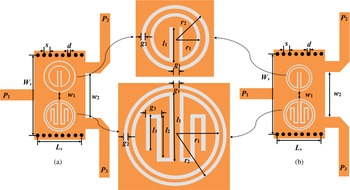
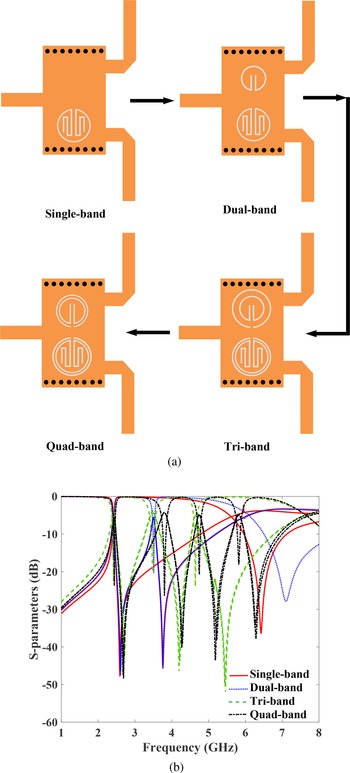
Figure 1(a) corresponds to tri-band and 1(b) corresponds to quad-band SIW PD. It is observed that the structure of both the tri and quad-band PDs are the same except for slight variation. In order to understand the development of quad-band PD, its evolution starting from the single-band structure to the quad-band structure is illustrated along with its corresponding S-parameter results in Figs 2(a) and 2(b) respectively. Initially, to achieve power division at f 1 = 2.42 GHz, a single-ring MC-CSRR consisting of circular CSRR with meander-shaped slots is incorporated on the lower side of SIW rectangular cavity. The meander-shaped slots are utilized in order to increase their total electrical length. Then to account for the second operating frequency f 2 = 3.5 GHz, the upper resonator that consists of a single-ring circular CSRR with rectangular-shaped slots is utilized. To accommodate the third operating frequency f 3 = 4.65 GHz, a single-ring circular CSRR with the same radius is incorporated as the outer resonator enclosing both the upper and lower resonators. It is found that even if one of the outer resonator is removed, we are able to achieve the tri-band response. As the two outer resonators correspond to the third band frequency, removal of any one of the outer resonator does not have any effect on the response. However, to get equal power division, separation between the upper and lower resonators (w 1) needs to be adjusted. Finally to achieve quad-band PD shown in Fig. 1(b), the radius of the outer circular CSRR on the upper side is decreased to accommodate the fourth operating frequency f 4 = 5.82 GHz.
Configuration of the proposed (a) tri-band and (b) quad-band SIW PD.

(a) Evolution of tri- and quad-band SIW PD and (b) its corresponding S-parameters.

As far as the resonators are concerned, they are aligned face-to-face with regard to the outer split-ring direction. The electric field concentration is maximum in the waveguide center, and as a result, the coupling is stronger between the waveguide and the MC-CSRRs [Reference Dong, Wu and Itoh8]. The metalized vias realize the electric sidewalls of the SIW. The two output ports are oriented 180 degrees opposite to each other and they are symmetrically placed with respect to the input port so that input power is equally split between the output ports.
The proposed PD operates based on the principle of the theory of evanescent mode propagation. These resonators act as an electric dipole and when excited by an axial electric field; create multiple passbands due to the excitation created by the inner and outer resonators. The first passband is generated at a frequency lower than SIW cutoff frequency and hence ensures the miniaturization of the proposed tri and quad-band SIW PD prototype. Table 1 gives the fine-tuned dimensions of the proposed tri-band and quad-band SIW PD.
Dimensions of the proposed tri-and quad-band SIW PDs (unit: mm)

The design procedure of the SIW multi-band PD is as follows:
• Initially, the cutoff frequency of dominant mode of SIW (TE 10) is calculated by utilizing the formulas [Reference Chen, Zhang and Yu2]:
(1)$$f_c{( _{{TE}_{10}}}) = {c\over 2W_{eff}{\sqrt{\epsilon_r}}}$$ (2)$$W_{eff} = W_s-{d^2\over 0.95s}$$Where W s and W eff represent the width and the effective width of the SIW cavity.
• To maintain the leakage losses as minimum as possible, the center to center spacing s between the metallic vias is considered as less than or equal to twice the diameter of the metallic vias d.
• Secondly, due to the influence of mixed electric and magnetic field coupling of the multiple CSRRs; multiple passbands are generated and the first operating frequency is observed to be lower than the SIW cut-off frequency.
• The total length of the resonators is chosen as λg/2, so as to provide power division at the required frequency. The guided wavelength is given by,
(3)$$\lambda_g = {c\over f_{desired}{\sqrt{\epsilon_{eff}}}}$$where εeff is determined by,
(4)$$\epsilon_{eff} = {\epsilon_r + 1\over 2}$$• The operating frequency of the PD can be arbitrarily controlled by modifying the dimensions of the proposed resonators.


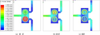
The E-field distribution of the proposed tri-band SIW PD is illustrated in Fig. 3 for the respective three operating frequencies. It can be seen that at f 1 = 2.42 GHz, the inner MC-CSRR (MC-CSRR) with meander-shaped slots gets excited, whereas at f 2 = 3.48 GHz the inner circular CSRR with rectangular slots is excited and at f 3 = 4.64 GHz, the outer single-ring circular CSRR gets excited. Thus, the relationship between the operating frequencies and the corresponding resonator electrical length is visually interpreted using E-field distribution of the proposed PD prototype. Similar response can be observed from E-field distribution of quad-band SIW PD prototype.
Electric field distribution of the proposed tri-band SIW PD at three operating frequencies.

Equivalent circuit of the proposed tri-and quad-band SIW PD
Figure 4 demonstrates the equivalent circuit model of the proposed tri-band SIW PD. It is clear that SIW is modeled as a two-wire transmission line which is loaded by a number of short-circuited stubs providing shunt inductance L via. The resonators are modeled as a shunt-connected resonant tank consisting of inductance L ri and capacitance C ri. For tri-band PD, there are three such resonator tanks (i = 1, or 2, or 3) to account for tri-band operation. The initial capacitance of the resonator (C r) is calculated from the known relation which includes the area of the resonator as in [Reference Selvaraju, Jamaluddin, Kamarudin, Nasir and Dahri26].

From the known resonant frequency of the resonant tank circuit given below the inductance L r is computed.

Equivalent circuit of the proposed tri-band SIW PD.

The magnetic coupling through the split of the slot ring between the waveguide transmission line and the ring resonators is denoted by L ci (i = 1 or, 2 or 3). C ci (i = 1 or, 2 or 3) indicates the capacitive coupling realized by the slot coupling between the waveguide and the CSRRs. The location of transmission zero is determined from the relation,

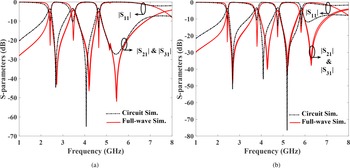
Same circuit model is exploited in case of quad-band PD, where four resonant tank circuits (i = 1, or 2, or 3, or 4) and four coupling elements are used. The extracted lumped elements of the equivalent circuit model are fine-tuned using optimization process so as to get a close replica of the HFSS simulation results. Table 2 shows the extracted electrical parameters of the proposed tri and quad-band SIW PD. The full-wave simulation results of the proposed tri and quad-band SIW PD from HFSS are plotted along with circuit model simulation results in Figs 5(a) and 5(b) respectively. It is found that a good agreement is attained between both of them which validates our design methodology.
Full-wave and circuit-simulated results of the proposed (a) tri-band, and (b) quad-band SIW PD.

Extracted electrical parameters of the proposed tri-and quad-band SIW PD

Note: L via = 1.2 nH, all inductance (in nH) and capacitance (in pF).
The bandwidth (BW) of the proposed tri and quad-band SIW PD can be enhanced by cascading two-stage PD, where the desired BW is achieved by controlling the mutual coupling between them. For instance, Fig. 6 illustrates the BW improvement of the proposed quad-band SIW PD by cascading two stages centro-symmetrically. By changing the position of two output ports, unequal power division is possible in the proposed PD.
Simulated S-parameters of the cascaded tri-band SIW PD.

Experimental results
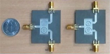
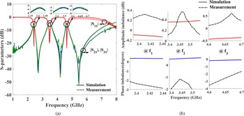
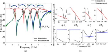
The proposed tri-band and quad-band SIW PD prototypes are implemented on a Rogers RT/Duroid substrate with a permittivity of 2.33, the dielectric loss tangent of 0.0012, and a height of 0.787 mm. The photographs of the fabricated tri-band and quad-band SIW PD prototype are depicted in Fig. 7. For the easiness of comparison, both simulated and measured S-parameters results are illustrated in Figs 8 and 9, along with an expanded view of the insertion loss at each of the operating bands to demonstrate the power division.
Photograph of the fabricated (a) tri-band and (b) quad-band SIW PD.

Simulated and measured results of tri-band SIW PD (a) transmission and reflection, (b) amplitude imbalance and phase imbalance.

Simulated and measured results of quad-band SIW PD (a) transmission and reflection, (b) amplitude imbalance and phase imbalance.

It can be seen that for the tri-band PD, the measured center frequencies are located at 2.41, 3.46, and 4.65 GHz. The measured in-band insertion loss and return loss are found to be < 2.21 and > 19.34 dB respectively. Moreover, the measured amplitude and phase differences between the output ports at these three passbands are < 0.55 dB and > −2.77° respectively. Table 3 summarizes the performance comparison of the simulated and measured results of the proposed tri and quad-band SIW PD.
Simulated and measured results of the proposed tri-and quad-band SIW PD

CF, center frequency; FBW, fractional bandwidth; IL, insertion loss; RL, return loss; AI, amplitude imbalance; PI, phase imbalance.
The quad-band SIW PD operates at these four frequencies 2.42/3.78/4.74/5.8 GHz with tested insertion loss and return loss of < 2.72 and > 17.6 dB respectively. It is noticed that the tested amplitude and phase imbalances are found to be < −0.245 + 0.5 dB and 6.62 − 3° at these four operating frequencies. The measured results agree well with the simulated results, except for the slight deviations that occurred during connector soldering, fabrication, and measurement. The proposed equal SIW tri-band and quad-band PDs occupy a compact area of 0.205λg × 0.094λg, where λg represents the guided wavelength at the first operating frequency.
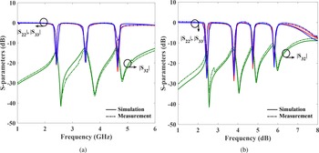
The measured isolation between the output ports is found to be > 12.8 and > 10.86 dB for the tri-band and quad-band SIW PDs respectively as shown in Figs 10(a) and 10(b). The output port return losses are found to be more than 17.9 and 21 dB for the tri-band and quad-band SIW PDs respectively. The performance of the proposed tri-band and quad-band SIW PD is compared with other reported multi-band SIW PDs in literature and summarized in Table 4. It can be concluded that the size of the proposed tri-band and quad-band PD is highly reduced compared to other PDs [Reference Duraisamy, Barik, Sholampettai Subramanian and Kamatchi16–Reference Pradhan, Karthikeyan, Barik and Cheng25]. The return loss is found to be better than [Reference Wang, Zhou, Zhou and Wu19, Reference Barik, Cheng, Pradhan and Karthikeyan20, Reference Hua, Wu, Liu and Chen22]. The increase in insertion loss is due to high conductor loss contributed by the modifications of the resonator structure by making it to be more compact with the addition of rectangular slots and meander-shaped slots along with the inner space of circular CSRR so as to increase its total electrical length [Reference Dong, Wu and Itoh8]. The insertion loss of the proposed PD is <2.6 dB (excluding the inherent 3 dB power division) which is smaller than 4.85 dB in [Reference Pradhan, Karthikeyan, Barik and Cheng25]. In general, PD circuit insertion loss should be 3 dB and hence it is quite an acceptable level as in the other literature.
Simulated and measured isolation (|S 32|) and output return loss (|S 22| and |S 33|) of the proposed SIW PD for (a) tri-band and (b) quad-band.

Comparison of the proposed SIW PD with other related works

.
Conclusion
In this paper, the design approach for a compact SIW-based tri and quad-band PD is presented. By incorporating multiple face-to-face oriented modified asymmetric single-ring circular CSRRs, equal power division is achieved at multiple frequencies. The first operating passband of PD is obtained at a frequency lower than the SIW characteristic cutoff that leads to the compactness of the proposed structure. By changing the dimensions of the proposed MC-CSSRs, it is possible to achieve equal power division at the desired frequency of interest. The equivalent circuit is extracted and its circuit simulation results agrees well with full-wave simulations. To demonstrate the performance of the proposed design, two PD prototypes with tri-band and quad-band operations are fabricated and tested. The results obtained using full-wave simulations and experimental measurements are similitude to each other. The proposed tri-band and quad-band SIW PD meets the key specifications such as reasonable insertion loss, isolation, better in-band return loss, good selectivity, and compact structure useful for WLAN (2.42/5.8 GHz), WiMAX (3.78 GHz), 5G (3.46 GHz), and INSAT (4.4–4.8 GHz) applications.
Acknowledgments
This work is partially supported by the National Institute of Technology Trichy seed grant NITT/R&C/SEEDGRANT/19- 20/P.09/ECE/SSK, National Natural Science Foundation of China Grant 61471258 and University Key Research Project of Guangdong Province under Grant 2018KZDXM063.
 Tharani Duraisamy received her B.E. degree in Electronics and Communication Engineering from J.J. College of Engineering and Technology Tiruchirappalli, India in 2010. She received her M.E. degree in Communication Systems from Saranathan College of Engineering, Tiruchirappalli, India in 2013. She is now a Research Scholar with the Department of Electronics and Communication Engineering in Indian Institute of Information Technology, Kancheepuram, India. Her main research interests are design of SIW passive components such as power dividers, filters, and diplexers. D. Tharani is a Student member of IEEE.
 Selvajyothi Kamakshy studied at Thangal Kunju Musaliar College of Engineering, Kollam, India and received the B.Tech degree (1995) in Electrical and Electronics Engineering from Kerala University, India. She received the M.E. degree (2004) in Power Electronics and Industrial Drives from Sathyabama Institute of Science and Technology, Chennai, India. She received the Ph.D. degree in Electrical Engineering from the Indian Institute of Technology, Madras in 2009. Currently, she is an Assistant Professor in Electrical Engineering, Indian Institute of Information Technology Design and Manufacturing, Kancheepuram, India. She has 20 years of teaching experience. Her areas of interest are control and Instrumentation engineering, electric vehicles, medical instrumentation, power electronics and control. Dr. Selvajyothi is a Life Member of ISTE. She is a member of IEEE, IIIS, and ESSI.
 Karthikeyan Sholampettai Subramanian received the Ph.D. degree from IIT Guwahati, India, in 2011. He has 13 years of educational activity and research experience in the area of RF and microwave. He was the Short-Term academic foreign visit UK and France. He is currently an Assistant Professor with the Department of Electronics and Communication Engineering, National Institute of Technology, Tiruchirappalli, India. He has authored or co-authored more than 100 scientific research papers and technical reports. His current research interests include microwave integrated circuits, biological effects of microwaves, computer-aided design of MICS, metamaterials/frequency selective surfaces (FSSs), fractal antennas, MIC antennas, metamaterial antennas, and substrate-integrated waveguides. Dr. Karthikeyan is a Chair of the IEEE-APS Society Madras chapter. He is a member of the IEEE, IEEE MTT-S, and IEEE AP-S. He is a Life Member of the ISTE.
 Rusan Kumar Barik received his B.Tech degree in Electronic & Communication Engineering from Biju Patnaik University of Technology, Rourkela, India in 2012, M.Tech degree in Communication Systems Design, and a Ph.D. degree in Electronics Engineering from Indian Institute of Information Technology, India in 2015 and 2018, respectively. He joined the Department of Electronic & Communication Engineering, Christ University Bangalore, India, as an assistant professor in 2018. In 2019, he joined a post-doctoral researcher in the Department of Electrical and Electronic Engineering, Southern University of Science and Technology, Shenzhen, China. Currently, he is working as a post-doctoral researcher with the Engineering Optimization & Modeling Center (EOMC), Department of Electrical Engineering, Reykjavik University, Iceland. His research interests include multiband microwave devices, SIW components, surrogate-based modeling and optimization.
 Qingsha S. Cheng received the B.Eng. and M.Eng. degrees from Chongqing University, Chongqing, China, in 1995 and 1998, respectively, and the Ph.D. degree from McMaster University, Hamilton, ON, Canada, in 2004. In 1998, he joined the Department of Computer Science and Technology, Peking University, Beijing, China. In 1999, he joined the Department of Electrical and Computer Engineering, McMaster University, where he worked as a postdoctoral fellow, a research associate, and a research engineer. He is currently an Assistant Professor with the Department of Electrical and Electric Engineering, Southern University of Science and Technology, Shenzhen, China. His research interests include surrogate modeling, CAD, modeling of microwave circuits, software design technology, and methodologies for microwave CAD.