Introduction
Metamaterials (MMs), also called left-handed materials, have simultaneously negative electrical permittivity ɛeff and negative magnetic permeability μeff. The split-ring resonators (SRRs) are main components of MMs. In 1999, the first SRR was proposed by Pendry as a resonant magnetic particle designed for effective negative permeability (μeff < 0) [Reference Pendry, Holden, Robins and Stewart1]. The effective negative permeability in a certain frequency range can be obtained using suitable SRR geometries [Reference Smith, Padilla, Wier, Nemat-Nasser and Schultz2, Reference Marques, Mesa, Martel and Medina3]. When a time-varying magnetic field (H) is applied parallel to the axes of the rings, current induced on the surface of the ring will depend on the resonant properties of the structure. It can produce an internal magnetic field that may either enhance or oppose the incident field. Permeability (μeff) can be positive below the resonant frequency and it becomes negative at higher frequencies. Again, the effective negative permittivity (ɛeff < 0) of complementary SRRs (C-SSRs) was proposed to design narrow band-stop filters [Reference Katsarakis, Koschny, Kafesaki, Economou and Soukoulis4–Reference Bonache, Gil, Gil, García-García and Martín6]. A microstrip line is a compact transmission line which is used to transmit microwave signals. Both SRR and C-SSR are able to pass/stop signal propagation through a transmission line at the fundamental resonance mode. The SRRs are generally small resonant elements with high-quality factor at microwave frequency. Now, the SRR loaded microstrip line can also offer a high Q-factor that is very useful for both microwave and terahertz bio-sensing applications [Reference Asci, Sadeqi, Wang, Nejad and Sonkusale7–Reference Cinar and Bicer10] and also, for thin-film sensing applications [Reference Chen, Li and Sun11]. The band-stop filter is one of the most important microwave components to filter out or to reject the unwanted signals, but pass desired signals. So, the band-stop filter plays a key role in the wireless systems. For stop-band response, the microstrip lines loaded with single SRR and also with cascaded SRRs for different orientations have been proposed in [Reference Asci, Sadeqi, Wang, Nejad and Sonkusale7–Reference Bojanic, Milosevic, Jokanovic, Medina-Mena and Mesa13]. To calculate the resonance frequency of this type of coupled system, the equivalent circuit model may help us. The resonance frequency of this system will depend on electric and magnetic coupling coefficients which depend on geometrical properties of SRR and microstrip transmission line (MTL). Moreover, its resonance frequency will depend on the split-gap orientation of SRR.
A classical Lagrangian approach can be used for better understanding of the physics of the propagation phenomena through MTL. Earlier, the resonance properties with radiation properties of a magnetic dimer (MD) [Reference Liu, Genov, Wu, Liu, Liu, Sun, Zhu and Zhang14, Reference Li, Liu, Li, Wang, Cao, Zhu, Dong, Zhu and Zhang15] were successfully described by a quasi-molecular hybridization model using Lagrangian approach. An MD consists of two single-gap split-ring resonators coupled through magnetic induction. It has potential application for optical devices. Also, the near-field coupling within SRR-MMs [Reference Powell, Lapine, Gorkunov, Shadrivov and Kivshar16] has been analyzed using Lagrangian approach, taking into account both the relative orientation and the offset between the centers of two neighboring resonators. Here, both the electric and magnetic interaction coefficients have been calculated. Again, the magnetic dipole coupling between inner and outer SRRs [Reference Jing, Guang-Yong and Wei-Ren17] can show a strong magnetic interaction. By introducing magnetic and electric interaction terms into the Lagrangian formalism, the electromagnetic coupling effect on the magnetic resonant frequency was investigated. Moreover, the Lagrangian and dissipation functions have been proposed in typical dispersive and absorptive MMs with finite losses [Reference Pi-Gang Luan18]. Also, a one-dimensional magnetic plasmon (MP) propagating in a linear chain of single SRRs was proposed in [Reference Liu, Genov, Wu, Liu, Steele, Sun, Zhu and Zhang19], where the sub-wavelength size resonators interact mainly through exchange of conduction current, resulting in stronger coupling as compared to the corresponding magneto-inductive interaction. To better understand the interactions involved in the splitting of the MP resonance, a comprehensive semi-analytical theory based on the attenuated Lagrangian formalism has been developed. In addition, a Lagrangian model has been presented to investigate the chiral optical properties of stereo-MMs [Reference Liu, Cao and Zhu20], where the phase retardation effect due to the three-dimensional stacked configuration has been taken into consideration.
However, making use of the Lagrangian formulation, nobody has so far investigated the characteristics of a microstrip line coupled to a SRR. Here, a simple formula is derived to obtain the resonant mode frequency of this coupled system for three different configurations of SRR with transmission line. In loaded microstrip line, the coupling between electric dipoles together with coupling between magnetic dipoles may significantly affect the resonance characteristics. At resonance mode frequencies, the electromagnetic wave strongly couples with the SRR and produces an oscillating current in the structure. As a result, a strong electric field would be created in the split-gap. Also, a magnetic field cuts through the ring. In this work, the mutual inductance between MTL and SRR, and the changes in the capacitances of the MTL and the SRR due to the effects of coupling between MTL capacitance and SRR capacitance for parallel and perpendicular split-gap orientations of SRR have been analyzed for various separation distances between MTL and SRR, various side-lengths of SRR, and also, for various heights of the dielectric substrate. The magnetic coupling co-efficient between MTL and SRR, and also, the electric coupling co-efficient between MTL capacitance and SRR capacitance have been calculated for the various separation distances. The validity of the equivalent circuit models is confirmed by using CST Microwave Studio full-wave electromagnetic simulations. To model an SRR-loaded MTL with very high Q-factor, this type of analysis is very useful for microwave and terahertz bio-sensing, thin-film sensing, and also, for microwave filter applications.
Device description and Lagrangian formulation
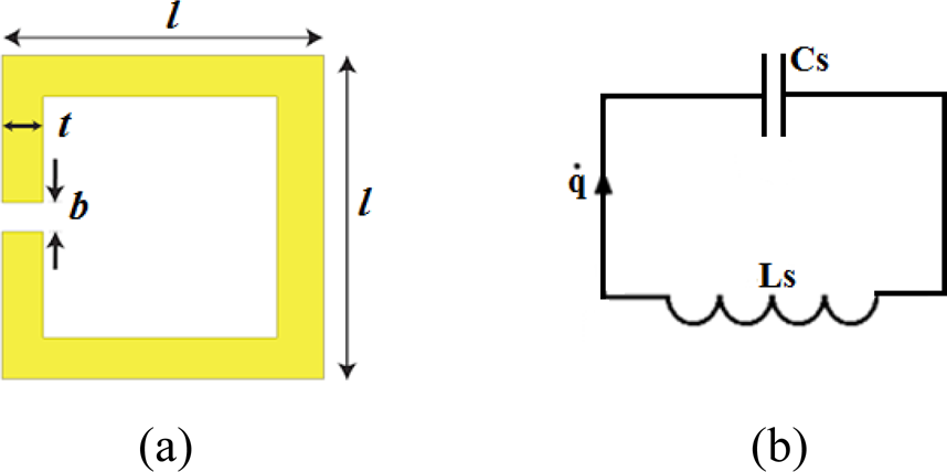
A schematic diagram of a square-shaped SRR is shown in Fig. 1(a) and its equivalent circuit is presented in Fig. 1(b). An SRR consists of a magnetic loop with inductance L S associated with the metal ring and a capacitance C S that corresponds to the split-gap of the ring. (Actually, the side surface of the SRR also contributes to the capacitance.) Therefore, the SRR can be described as an equivalent L-C circuit with a fundamental resonance frequency of $\omega _0 = ( {L_SC_S} ) ^{-{1 \over 2}}$ . Considering charge accumulation in the split-gap, the Lagrangian description of an SRR can be formulated in terms of the time-dependent charge (q) as the generalized coordinate and current ($\dot{q}$
 ) as the corresponding velocity.
(a) Schematic view of an uncoupled SRR, and (b) its equivalent circuit model.

When the SRR is excited by an incident electro-magnetic wave, the Lagrangian can be written as [Reference Jing, Guang-Yong and Wei-Ren17]

where ${1 \over 2}L_S\dot{q}^2$ and ${1 \over 2}{{q^2} \over {C_S}}$
 refer to the kinetic energy stored in the loop and the electrostatic energy stored in the split-gap, respectively. So, the equation of motion (i.e. the Euler–Lagrange equation) is

By solving Euler–Lagrange equation, it is straightforward to obtain the resonance frequency of SRR from

or,

In calculating the resonance frequency of the SRR, its loss and radiation resistances are not considered in this circuit model.
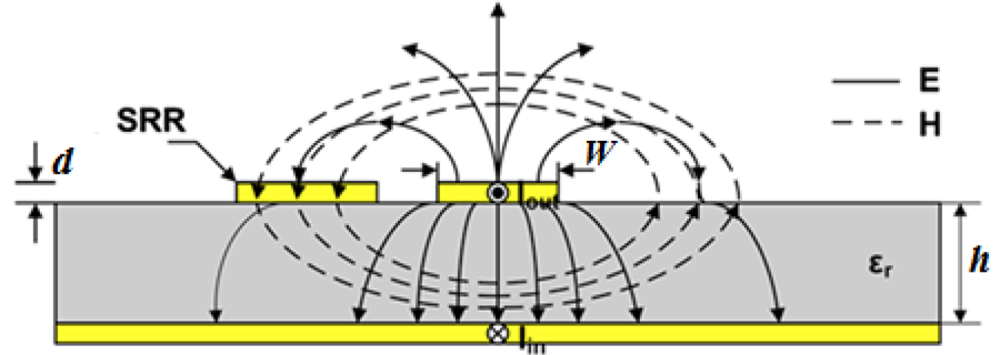
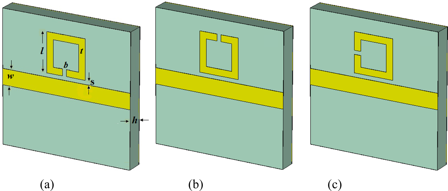
A “SRR loaded microstrip line” is shown in Fig. 2. Taking its equivalent π-network model, the lumped parameters per section of the unloaded line comprise of an inductance (L) and a capacitance (C). In this circuit model, the losses are disregarded, which is a reasonable assumption for low-loss dielectric substrates. When the SRR is placed near to a microstrip line and they are excited, energy is exchanged between them through overlapping of their electric and magnetic fields. As a result, the system acts as a pair of coupled harmonic oscillators. Depending upon the relative orientation of SRR with respect to the MTL, the coupling via electric and magnetic dipole moments and higher moments will vary. We shall analyze the nature of the couplings for various orientations of SRR by adopting the Lagrangian formalism. Figure 3 shows the layouts for three different split-gap orientation of SRR with MTL. The loaded SRR having parallel split-gap are of two types: (i) parallel split-gap of SRR near to the line in Fig. 3(a), and (ii) parallel split-gap of SRR far from the line in Fig. 3(b). Another has the split-gap of the SRR in perpendicular orientation, which is shown in Fig. 3(c).
Electric (E) and magnetic field (H) distribution associated with the microstrip line.

Layout of SRR coupled microstrip line for (a) a parallel split-gap orientation near to the line, (b) a parallel split-gap orientation far from the line, and (c) a perpendicular split-gap orientation.

With parallel split-gap orientation of SRR
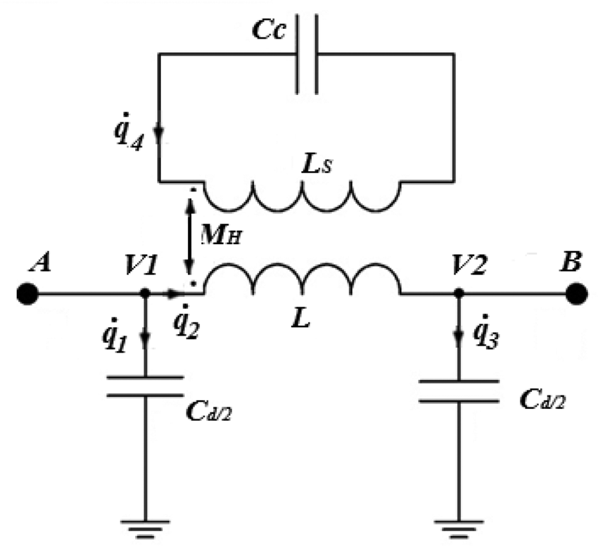
Resorting to single-mode approximation, a lumped-element equivalent circuit (as in Ref. [Reference Bojanic, Milosevic, Jokanovic, Medina-Mena and Mesa13]) in Fig. 4 is considered to calculate the resonant mode frequency of this coupled system.
Equivalent circuit model of coupled SRR and microstrip line is shown.

The Lagrangian formalism for this case runs as follows:
In view of the high Q-value (≥10) of the device, and so, a small rate of energy dissipation and radiation in the microwave range, the kinetic energy term including magnetic interaction of the oscillators can be written as (using Refs [Reference Li, Liu, Li, Wang, Cao, Zhu, Dong, Zhu and Zhang15–Reference Jing, Guang-Yong and Wei-Ren17])

where the first two terms are energy stored in the inductors and the last term, having M H, the mutual inductance, represents the energy associated with magnetic interaction. This quantity, M H, can be positive or negative.
Again, the potential energy of this coupled system is

where C c and C d are, respectively, the effective capacitance of the coupled SRR and microstrip line. The capacitance of a charged conductor increases if a metal sheet or strip is brought near it. This happens on account of the lowering of the potential of the charged conductor due to the induced charges of opposite sign on the strip. We may write C c = C S + C SRR−MS; the change (C SRR−MS) is roughly proportional to the inverse cube of the distance between SRR and MTL, and may also involve higher inverse-powers. A similar expression can be written for C d. Basically, the distance between the two conductors is the distance between the split-gap and the microstrip line. The mutual inductance between the SRR and the MTL, on the other hand, varies inversely as (and also, the next few higher inverse-powers of) the distance between them since the magnetic field over the ring, due to the current in the MTL, varies roughly in that manner. Variation of resonance frequency can be explained on the basis of the natures of variation of C SRR−MS and M H.
Now, the Lagrangian for the system can be written as

The Euler–Lagrange equations of this coupled system are


and


From (13), it is observed that when V 1 = V 2 (suggesting band pass filtering action) the SRR loaded microstrip line can be described by an oscillatory equation for the charge q 4:

So, the resonance mode frequency is

Here, $k_m\left({ = M_H/\sqrt {LL_S} } \right)$ is the magnetic coupling co-efficient between microstrip line and SRR.
Note that when the distance between the split-gap and the microstrip is small, the variation of C SRR−MS with distance (rapid rise with decreasing distance) plays the dominating role in deciding how the resonance frequency changes. However, when the distance is large, the variation of M H determines how resonance frequency changes.
With perpendicular split-gap orientation of SRR
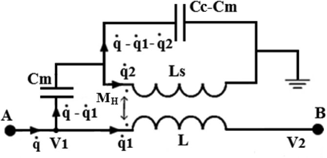
An equivalent circuit (as in Ref. [Reference Bojanic, Milosevic, Jokanovic, Medina-Mena and Mesa13]), for the configuration having the split-gap of the SRR in perpendicular orientation with respect to the MTL, is shown in Fig. 5. The perpendicular component of the electric field of the MTL is parallel to the split-gap which causes a strong electric coupling. In the equivalent circuit model, Cm (called coupling capacitance) comes from this additional electric coupling between the microstrip line and the SRR.
Equivalent circuit model, for a loaded microstrip line with vertical split-gap SRR, is shown.

Now, to calculate the resonance frequency, we again consider the Lagrangian formalism. Assuming no dissipation of energy as for the parallel split-gap orientation of SRR, the kinetic energy (using Refs [Reference Li, Liu, Li, Wang, Cao, Zhu, Dong, Zhu and Zhang15–Reference Jing, Guang-Yong and Wei-Ren17]) is

Also, the electrostatic energy is

Combining (16) and (17), and using the Euler–Lagrange formalism, the equations of motion are found to be


and

The condition for the resonance can be expressed as having nontrivial solutions for q and q 2 when the output voltage at port B, V 2 = 0 (i.e. q 1 = 0 at all times; hence, $\dot{q}_1 = \ddot{q}_1 = 0$ .) So, our equations reduce to


and

From (23), we have

Moreover, using (23) in (21) we get

Again, using (25), (23), and (24), we get

This leads to the resonance mode frequency of the coupled system

The magnitude of ${{( {L_SC_{SRR-MS}-C_mM_H} ) } \over {L_SC_S}}$ is the square of the effective coupling co-efficient of this coupled system, and (27) can be re-written as

In (28), the positive sign applies when L SC SRR−MS > C mM H and the negative sign applies when L SC SRR−MS < C mM H. The quantity k E is the effective coupling co-efficient between the microstrip line and the SRR for perpendicular split-gap orientation of SRR. So, the microstrip line may show a lower frequency resonance mode depending on the sign of Cm when coupled with an SRR with perpendicular split-gap. As V 2 = 0, this is the band stop or notch configuration. Note that there will be no effect on the resonance frequency if, for the perpendicular orientation of the gap, the split-gap appears in the opposite arm of the ring.
Simulation, calculation, and analysis: also comparison of analytical results with previously published results
To analyze the coupling between the microstrip line and the SRR for each split-gap orientation of SRR, the coupled mode frequency was computed for different separation distances between the nearest edges of the SRR and MTL. The variation of the coupled mode frequency was actually found for two alternative cases.
Variation with substrate height for a particular side-length of a square loop (we have taken l = 3 mm)
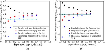
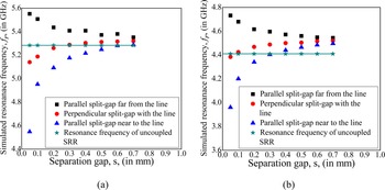
At first, we show in Fig. 6, the resonance mode frequencies as obtained for different coupling distances, which is the separation (denoted by s) between the nearest edges of an SRR and MTL, for the substrate height (h) of 0.65 and 1.27 mm. Also, the fundamental simulated resonance frequency of uncoupled SRR is shown for both cases in the mentioned figures.
Variations of resonance mode frequency with edge-to-edge separation between MTL and SRR, at a substrate height of (a) 0.65 mm, and (b) 1.27 mm, are shown for near, far, and vertical split-gap orientation of SRR.

It is observed that when the split-gap of the SRR is on the distant parallel arm, the coupled system shows a higher frequency resonance mode which decreases with the increase of separation. But, the resonance mode frequency increases with the increase in separation distance when the split-gap of the SRR is on the nearer parallel arm and also, with the perpendicularly oriented split-gap of SRR. Again, for the last two split-gap orientations, a lower frequency resonance mode occurs at shorter distances and the higher frequency resonance mode is obtained at larger separations. Due to a decrease of mutual inductance, beyond a certain distance, the mode frequencies settle down to the fundamental resonance frequency of uncoupled SRR at the substrate height of 1.27 mm (see Fig. 6(b)). But, for the decreased substrate height of 0.65 mm, the resonance mode frequency for SRR, with parallel split-gap near to the line and also for SRR with perpendicularly-oriented split-gap, increases above the fundamental resonance frequency of uncoupled SRR (i.e. 6.288 GHz) with an increase of separation from 0.3 to 0.7 mm as shown in Fig. 6(a). This happens due to the fact that the coupling capacitance (i.e. Cm) becomes negative (the current through it has reversed direction) and its magnitude increases after a certain separation gap between the MTL and the SRR. The variations of coupled mode frequency, as noted above, are consistent with theoretical expectations as outlined at the end of sub-section “Variation with substrate height for a particular side-length of a square loop (we have taken l = 3 mm)”.
Now to calculate the value of mutual inductance (M H) between MTL and SRR for various distances, we may use (15) for parallel split-gap far from the line. At first, the value of C SRR−MS is assumed to be negligible with respect to C S. Then, the resonance frequency of this coupled system can be written as

where L is the inductance of the uncoupled MTL. The inductance of an MTL can be written as [Reference Paul21]

or,

where l 1 and W are the length and width of the MTL, respectively. Also, v is the free space light velocity. Again, the self-inductance of a single gap square-shaped SRR can be written as [Reference Samanta, Pradhan and Syam22]

where l and t are the side-length and width of the SRR, respectively. Further the capacitance of the single gap square-shaped SRR may be written as [Reference Samanta, Pradhan and Syam22]

where d and b are the thickness and split-gap of the SRR. Also, ɛg is the effective dielectric constant of the substrate (on which the SRR is fabricated) for the capacitance associated with the split-gap and ɛs is the corresponding quantity for the capacitance associated with the side-surface of the ring.
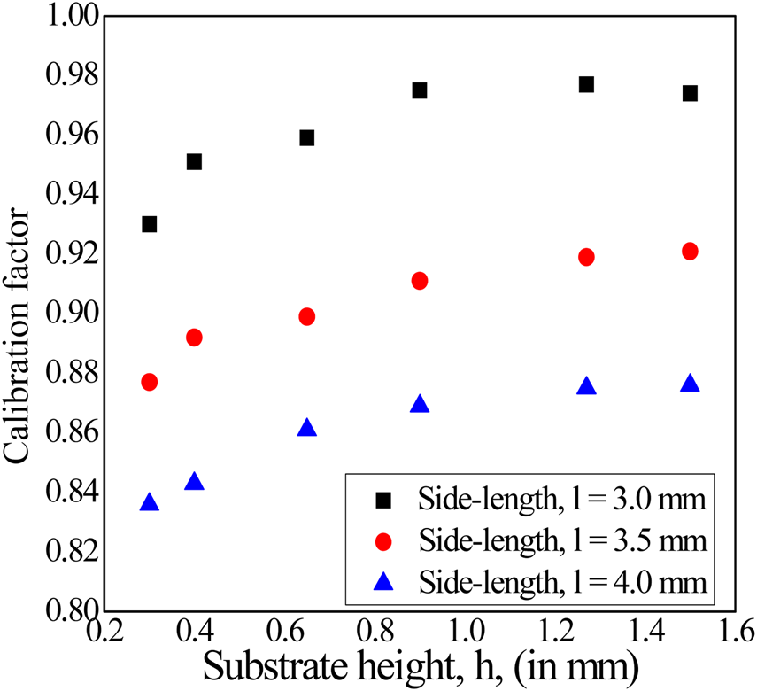
To determine the analytical expression of C S, the height of the dielectric substrate was considered to be infinite; in reality, this height is finite. Also, the effect of the metal sheet (on which the substrate is deposited) has not been considered for finding L S and C S. So, to rectify the error (i.e. in order to find the actual uncoupled resonance frequency from the analytical value), it is necessary to calibrate an SRR against simulated resonance frequency, for different substrate heights. For three different sides length of SRR (keeping fixed the other geometrical parameters), the calibration factor (=ratio of simulated SRR resonance frequency to analytical SRR resonance frequency) is plotted in Fig. 7 for various substrate heights. It is observed that for the side-length of 3 mm and the substrate height of 1.27 mm, the simulated SRR resonance frequency is close to analytical SRR resonance frequency.
Variation of calibration factor with substrate height is shown for three different values of side-length keeping fixed the other geometrical parameters of the coupled system.

Now, using simulation data for $f_{{\parallel} \_f}$ and f 0, and putting the analytical values of L and L S, we can evaluate the apparent value of M H for different intermediate distances (i.e. the distance of mid-point of the loop from the line which is assumed to be d 2 = (s + l/2), where l is the side-length of SRR loop). Plotting M H versus (s + l/2) graph and fitting the nature of M H by $b_1/d_2 + b_2/d_2^2 + b_3/d_2^3 + b_4/d_2^4$
 , the coefficients b 1, b 2, b 3, and b 4 could be determined. After that, putting the value of M H, the values of C SRR−MS at different separation gaps (i.e. where d 1 = (s + t/2), t is the width of the SRR), could be calculated from resonance frequency data for SRR with near parallel split-gap, given by

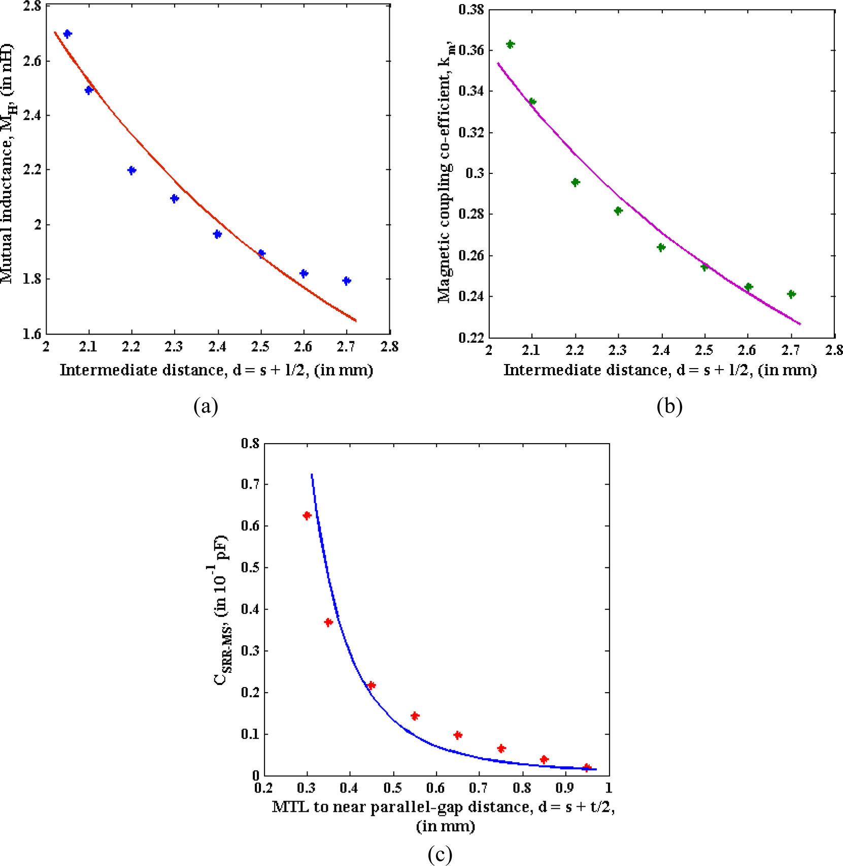
Next, plotting C SRR−MS versus (s + t/2) for near parallel split-gap orientation, and fitting the nature of C SRR−MS by $a_1/d_1^3 + a_2/d_1^4$ , we can work out approximate values of the two constants a 1 and a 2. Now, the contribution of C SRR−MS may be considered in (15) for parallel split-gap far from the line, when the separation gap is to be considered as d 3 = (s + l − t/2). After that, a revised value of M H could be determined from (34) and thereafter the constants b 1, b 2, b 3, and b 4 could be found properly from the plot of M H versus (s + l/2). Also, plotting k m versus (s + l/2) graph and fitting the nature of k m by $c_1/d_2 + c_2/d_2^2 + c_3/d_2^3 + c_4/d_2^4$
 , the coefficients c 1, c 2, c 3, and c 4 could be determined. Once more, a plot of C SRR−MS versus (s + t/2) would have to be made and fitting the data for C SRR−MS, we can determine improved values of the constants a 1 and a 2.
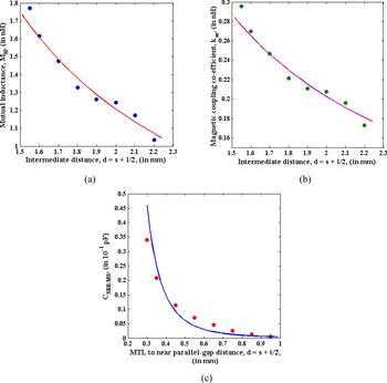
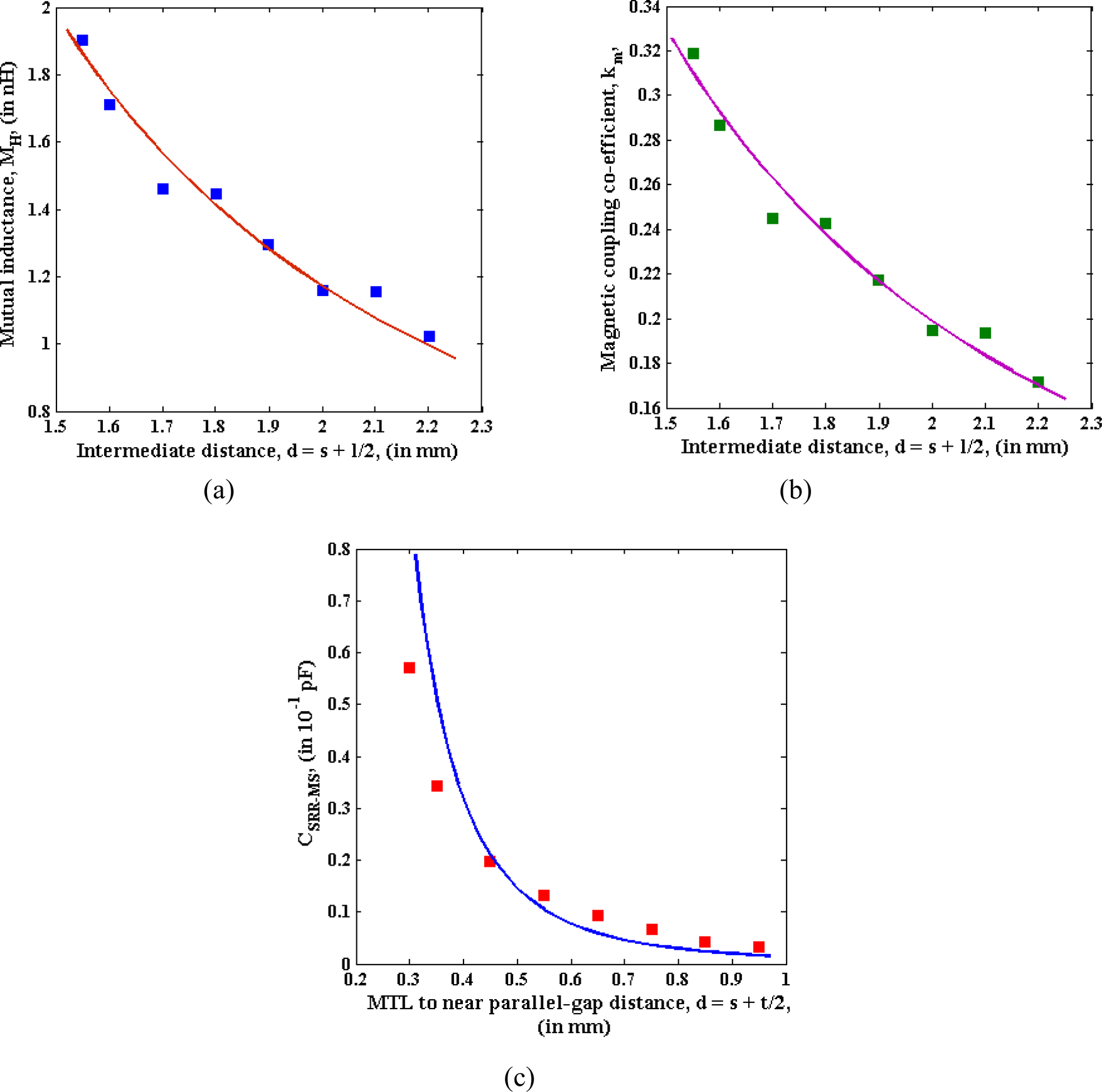
At first, for the substrate height of 0.65 mm, we have calculated the values of M H, k m, and C SRR−MS at various distances from MTL and plotted these in Figs 8(a)–8(c), respectively. Moreover, considering the analytical values of C S and C SRR−MS at vertical split-gap with different separation gaps, and using (27), the C m may be calculated for different distances. Also, the value of electric coupling co-efficient (k e) between C and C S can be calculated for different separation gaps.
Variations with distance of (a) mutual inductance, (b) magnetic coupling coefficient, and (c) the change in SRR capacitance are plotted for SRR at a side-length of 3 mm and a substrate height (h) of 0.65 mm.

The MTL capacitance per unit length (C 1) may be written as [Reference Paul23]

where d is the thickness of the MTL which is identical to the thickness of the SRR. Also, ɛr is the dielectric constant of the substrate.
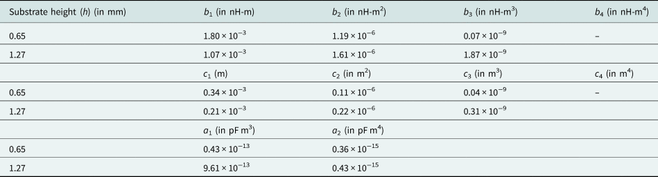
A list of analytical and simulated parameters is given in Table 1 for the substrate heights of 0.65 and 1.27 mm.

For MTL ,with SRR having a side-length of 3 mm and a dielectric substrate height of 1.27 mm, the (a) mutual inductance, (b) magnetic coupling co-efficient, and (c) the change in SRR capacitance.

Similar calculations have also been made for the substrate height of 1.27 mm and the corresponding plots are shown in Figs 9(a)–9(c). With perpendicular orientation of SRR split-gap, the mode frequency of the coupled MTL is above the uncoupled SRR resonance frequency for edge-to-edge separation between MTL and SRR of 0.05–0.7 mm. The list of calculated values of constants from Figs 9(a)–9(c) is given in Table 2 for two different substrate heights.
List of fitted constants for a split-ring with a side-length of 3 mm and the substrate heights of 0.65 and 1.27 mm

Variation with side-length of a square loop for a particular substrate height (h = 1.27 mm)
In this sub-section, Figs 10(a) and 10(b) are drawn to display the effect of coupling for different separations (i.e. s) between the nearest edges of the SRR and MTL for a particular substrate height of 1.27 mm, and SRR side-lengths of 3.5 and 4.0 mm. It is observed that the uncoupled resonance frequency of SRR decreases with an increase of side-length and also, the resonance mode frequency of MTL decreases at different separation distances.
Variations of resonance mode frequency of MTL, with separation from SRR, are shown for near, far, and vertical split-gap configurations, for SRRs with a side-length of 3.5 mm (Fig. 10(a)) and 4 mm (Fig. 10(b)) when substrate height is 1.27 mm.

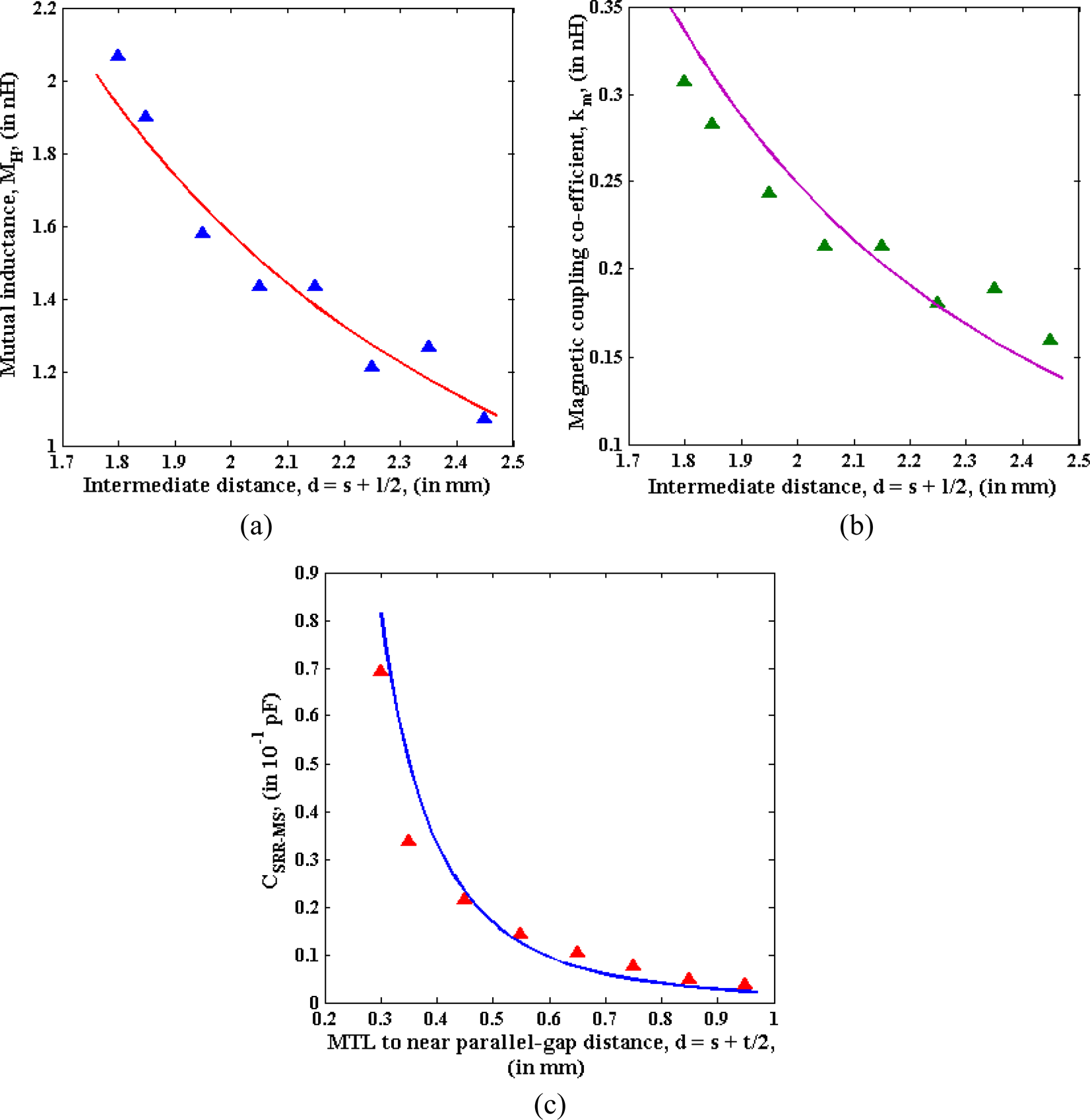
For the SRR with a side-length of 3.5 mm, numerical calculations have been carried out to study the variations of different parameters such as M H, k m, and C SRR−MS as shown in Figs 11(a)–11(c), as functions of separation distances. The results of similar calculations for the SRR of side-length of 4 mm are shown in Figs 12(a)–12(c).
Variations, with separation distance, of (a) mutual inductance, (b) magnetic coupling co-efficient, and (c) C SRR−MS, are plotted for MTL with SRR having a side-length of 3.5 mm and a substrate height (h) of 1.27 mm.

Plots of (a) mutual inductance, (b) magnetic coupling co-efficient, and (c) C SRR−MS are shown for different separation distances for MTL with SRR having a side-length of 4 mm and a substrate height (h) of 1.27 mm.

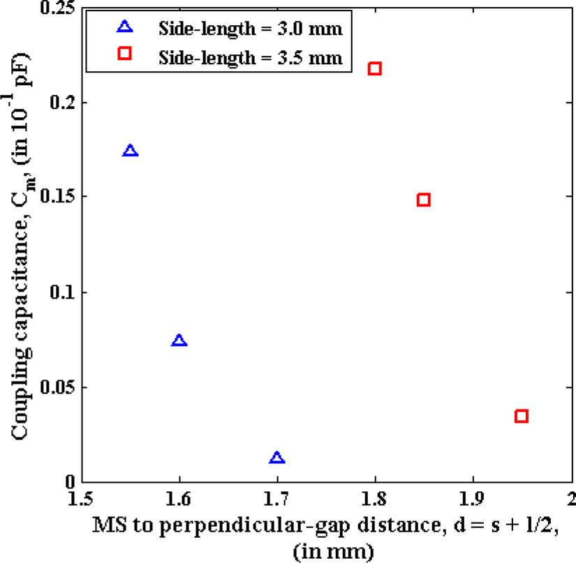
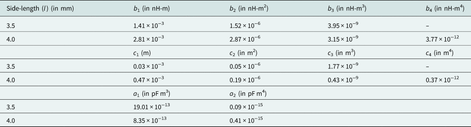
In Table 3 are shown the fitted constants for the SRR having a side-length of 3.5 and 4 mm, respectively. Other analytical and simulation parameters are presented in Table 4 for this coupled system for a substrate height of 1.27 mm. Again, the calculated value of C m has been shown for different distances in Fig. 13 (substrate height = 1.27 mm) for a side-length of 3.0 and 3.5 mm. It is observed that the coupling capacitance decreases with distance and it shows larger value for SRR of a side-length of 3.5 mm. The C m is not considered at higher edge-to-edge separation between MTL and SRR due to un-physical (negative) result in C m value. For a side-length of 4 mm, C m is positive over a very small range of SRR to MTL distance. This is the reason why we have no data corresponding to a side-length of 4 mm in Fig. 13.
The coupling capacitance is plotted for different separation distances between MTL and SRR, with SRR having a side-length of 3 and 3.5 mm.

List of fitted constants for a side-length of 3.5 and 4 mm for a substrate height of 1.27 mm


We can also calculate the electric coupling coefficient (k e) between C and C S at perpendicular split-gap orientation of SRR with respect to the MTL.
For our calculations, the analytical values of L S and C S are considered. But, the simulated resonance frequency of uncoupled SRR is used to calculate M H, k m, C SRR−MS, and C m. The analytical resonance frequencies are 6.557, 5.748, and 5.145 GHz for SRR side-length of 3, 3.5, and 4 mm, respectively, which differ from the simulated values, i.e. 6.404, 5.284, and 4.410 GHz, respectively.
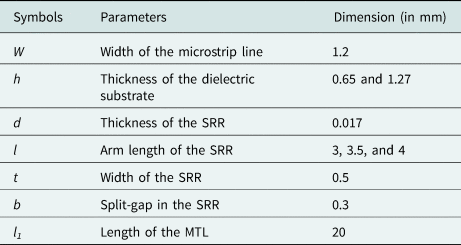
The list of other geometrical parameters which were used in simulations appears in Table 5. In our FW simulation, the Rogers (RO3010) has been assumed to be the substrate with a dielectric constant ɛr = 10.2.
List of geometrical parameters of the coupled system

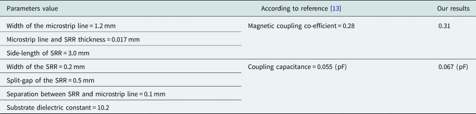
To compare with analytical results in [Reference Bojanic, Milosevic, Jokanovic, Medina-Mena and Mesa13], our analytical formula has been used to determine magnetic coupling co-efficient (i.e. k m) and electric coupling co-efficient (i.e. k e) for the given geometrical parameters in that reference. It is observed that our analytical value for k m and k e match well with the analytical results in that reference. The variation may be attributed to the difference in simulated resonance frequencies due to the use of different software. These are shown with the geometrical parameters in Table 6. The magnetic coupling coefficient between MTL and SRR, and the coupling capacitance between MTL capacitance and SRR capacitance for perpendicular split-gap orientation are shown in Table 6. In that table, the geometrical parameter values shown are the same as in Ref. [Reference Bojanic, Milosevic, Jokanovic, Medina-Mena and Mesa13]. In [Reference Bojanic, Milosevic, Jokanovic, Medina-Mena and Mesa13], the MTL inductance and capacitance, and also, the SRR inductance and capacitance have been found under coupled condition for a particular separation distance. The line parameters (i.e. L, C) have been obtained using LINPAR software under coupled condition. Then, the magnetic coupling co-efficient has been calculated using closed-form expressions for the resonance frequency and the minimum reflection frequency. To calculate the coupling capacitance, and also to find both sets of coupling coefficients at different coupling distances, it was necessary to repeat the analysis process. But, in our method, we do not need to repeat the analysis. Just putting the separation distance in the fitting formula and using appropriate coefficient values, we can find the coupling capacitance and the coupling coefficients.
List of geometrical parameters of the coupled system in [Reference Bojanic, Milosevic, Jokanovic, Medina-Mena and Mesa13] and comparison between analytical results

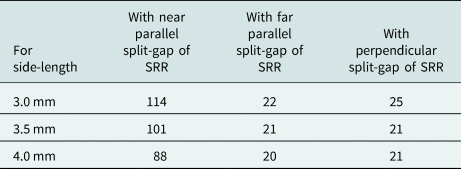
Using our parameters, we have calculated the Q-factor of this coupled system taking 1.27 mm as the substrate height and the edge-to-edge separation between SRR and MTL of 0.1 mm which is given in Table 7. The Q-factor is defined as f 0/Δf, where Δf is the bandwidth at −3 dB and also, f 0 is the center frequency. It is seen that the Q-factors are almost similar (about 22) for parallel split-gap of SRR far from the line and perpendicular split-gap SRR. But, for parallel split-gap of SRR near to the line, it is very high (about 100).
List of Q-factors with variation of side-length for different split-gap orientation.

Conclusion
We have adopted the classical Lagrangian approach to determine the resonance mode frequency of an MTL for different split-gap orientations of a coupled single gap square-shaped SRR. For various separation distances (between the MTL and the SRR), the coupled resonance frequency of microstrip line has also been determined with a commercial full-wave electromagnetic time-domain solver, CST Microwave Studio, based on the Finite-Integration Technique (FIT) for three different configurations of the split-gap. It has been observed that the MTL, with SRR having parallel split-gap far from the line, shows a coupled resonant mode with a higher frequency; but MTL with SRR having parallel split-gap near to the line has a lower frequency resonance mode at shorter separation distances and a higher frequency resonance mode at larger separation distances with respect to the fundamental resonance frequency of uncoupled SRR. Also, the system displays both of these features when the split-gap of the SRR is set perpendicularly to the MTL. Again, with the increase of substrate height from 0.65 to 1.27 mm, keeping fixed the other geometrical parameters, the simulated resonance frequency of uncoupled SRR was found to increase to a higher value and the lower frequency resonance mode started at larger distances as shown in Fig. 6. On the other hand, the opposite phenomena occur with an increase of side-length of the square loop as shown in Fig. 10. Using the expressions for resonance mode frequency, the mutual inductance between MTL and SRR, the magnetic coupling co-efficient between MTL and SRR, the change in SRR capacitance due to close placement of two conductors (i.e. MTL and SRR) and also, the coupling capacitance between MTL and SRR for perpendicular split-gap orientation have been studied for different separation distances with changing substrate height and side-length of the SRR in Figs 8, 9, 11–13, respectively. It is observed that the mutual inductances as shown in Figs 8(a), 9(a), 11(a), and 12(a), the change in SRR capacitances as shown in Figs 8(c), 9(c), 11(c), and 12(c), and the coupling capacitances as shown in Fig. 13 decrease with the separation distance. The results of calculations for the magnetic coupling co-efficient are shown for different separation distances in Figs 8(b), 9(b), 11(b), and 12(b), respectively. The fit parameters are presented in Tables 2 and 3. In addition, the list of analytical and simulated parameters is given in Tables 1 and 4. Also, a list of the geometrical parameters for this coupled system is given in Table 5. From our calculations, the simulated values of uncoupled SRR resonance frequency are 6.404, 5.284, and 4.410 GHz, respectively, for SRR side-length of 3, 3.5, and 4 mm. But the analytical resonance frequencies are 6.557, 5.748, and 5.145 GHz, respectively, for SRR side-length of 3, 3.5, and 4 mm, which are somewhat different from the simulated values. It is due to the assumption of infinite height of dielectric substrate; also, the effect of the metal sheet (on which the substrate is deposited) has not been considered for finding L S and C S. So, to rectify the error (i.e. in order to find the actual uncoupled resonance frequency from the analytical value), SRRs have been calibrated against substrate height for three different SRR side-lengths (keeping fixed the others geometrical parameters) by comparison with simulated resonance frequency, as shown in Fig. 7. It is observed that the simulated SRR resonance frequency decreases with an increase of SRR side-length. Also, the SRR shows higher resonance frequency for larger values of the substrate height. In our analysis, the magnetic coupling coefficient has been assumed (quite reasonably) to have the same value for all split-gap orientations at a particular edge-to-edge separation between MTL and SRR. Additionally, to justify our analytical model, a comparison has been made between our analytical results and the analytical results in Ref. [Reference Bojanic, Milosevic, Jokanovic, Medina-Mena and Mesa13]. This type of coupled system with very high Q-factor under particular coupling conditions is required to design notch filter and various bio-sensors in microwave and terahertz regimes.
Acknowledgements
Rajib Pradhan is grateful to the Research Centre of Midnapore College, India.
Financial support
Scheme of RUSA 2.0 component: 8 (620/MC/RUSA-2.0/PROJECT/19/13(7)).
Conflict of interest
None.
 Susanta Kumar Samanta received his B.Sc. degree in physics from the Vidyasagar University, Midnapore, India in 2011. He has also received his M.Sc. degree in electronics from the same university in 2013. He is currently working toward the Ph.D. degree. His main area of research interest is electromagnetic metamaterials.
 Rajib Pradhan received his Ph.D. degree on modeling of vertical cavity semiconductor saturable absorber for all-optical device applications from Vidyasagar University, West Bengal, India in 2018. He joined the Department of Physics Midnapore College, India in 2006 as an Assistant Professor. His present interest is (i) semiconductor optical amplifier and semiconductor saturable absorber-based photonic devices, (ii) dissipative soliton and cavity soliton, (iii) microwaves and terahertz metamaterials, and (iv) split-ring resonator-based transmission line for microwave device applications.
 Debapriyo Syam was born on August 27, 1953. He was educated in Kolkata (Calcutta). He received the M.Sc. degree in physics from Calcutta University and the Ph.D. degree in high energy physics from the Saha Institute of Nuclear Physics affiliated to Calcutta University. He taught at various Government Colleges of West Bengal, including the Presidency College (renamed Presidency University). From mid-1990s, he worked on theoretical and experimental aspects of nuclear track detectors, as well as on theoretical astroparticle physics, with collaborators from the Bose Institute (Calcutta). From September 2013 to August 2021, he was associated with the Centre for Astroparticle Physics and Space Science (CAPSS) at the Bose Institute. Apart from hard-core research he is interested in writing articles for students and teachers of undergraduate colleges.