



Introduction
Wideband and dual-band bandpass filters (BPFs) are commonly employed in wideband wireless communication systems to pick up the intended signal while filtering out unwanted signals. Modern communication technologies and remote working environments have enabled individuals worldwide to spend the majority of their time online. Particularly since the COVID-19 pandemic, there has been an upward trend in the work-from-home approach. With billions of users logging in at the same time, bandwidth becomes scarce, often due to the low data rate shared by numerous users. In these situations, ultra-wideband (UWB) communication technologies, which enable high data rates (10 Gb/s) at short distances (less than 10 m) or inside environments, come to life. The US Federal Communication Commission (FCC) allowed [1] the commercial use of the UWB spectrum (3.1–10.6 GHz) in 2002. Along with high data rates UWB system provides several appealing features, including cost reduction, increased capabilities, and minimum transmission power requirement. Even so, designing a BPF to attain the ultrawide bandwidth spectrum (3.1–10 GHz) requirement poses a few obstacles. Multiband BPFs are critical components in a communication system. Multiband frequency response is necessary for the Internet of Things (IoT) wireless communication systems of today, including Bluetooth, long-Range Radio (LoRa), Zonal Intercommunication Global Standard (ZigBee), NarrowBand (NB)-IoT, and Wireless Fidelity (WiFi). Furthermore, IoT wireless communication nodes necessitate low-power, miniaturized components. As a result, the RF front-end of an IoT device must be compact while still providing good electrical performance. Multiple variants [Reference Fang, Senshen and Feng2–Reference Hunter22] of a single and multiband BPF with different methodologies and designs have been introduced over the past few years. The author in [Reference Fang, Senshen and Feng2] proposes an UWB BPF filter with a double inter-digital structure and periodic slow-wave structure. However, the in-band selectivity and out-of-band rejection are compromised. The defect ground structure (DGS) is suggested in [Reference Liu, Ding, Chen and Zhang3], which comprises square loop microstrip lines and metal films. The design provides better fractional bandwidth (FBW), but electrical performance was suffered. In [Reference Chu and Tian4], an UWB BPF based on a stepped-impedance stub-loaded resonator is presented. To regulate the resonant frequencies, a stub-loaded step impedance resonator is utilized. The step impedance resonator (SIR) is utilized in [Reference Hung, Weng and Su5] to achieve wideband performance by suppressing spurious frequencies. Although, it is very difficult to realize the tight coupling of 100 microns in microstrip. A BPF based on irregular SIRs and defective split-ring resonators (SRRs) is presented in [Reference Luo, Cheng, Han, Zhang, Chen, Guo, Xia and Deng6]. However, the SIR's structure is hampered by design complexity. The asymmetric SIR was suggested in [Reference Chang, Kao, Weng and Yang7] for UWB performance with a wide stopband and excellent selectivity. An open-circuited slotline SIR vertical transition is presented in [Reference Yang, Zhu, Choi, Tam, Zhang and Wang8]. By adjusting the slotline SIR's impedance ratio, two transmission zeros (TZs) can be formed and relocated to enhance the passband selectivity. In [Reference Ji, Ji, Feng, Tong and Zhang9], a multilayer wide-band BPF is proposed using cascaded curved T-shaped microstrip patches on the top and bottom with a circular coupling structure in the mid-layer. A multilayer low-temperature co-fired ceramic technique [Reference Almorqi, Shaman and Alamoudi10] is another way to make miniaturized UWB BPFs. In [Reference Khalilpour11], the UWB BPF based on microstrip and SRR is presented. A microstrip ring with two parallel coupling gaps is used to expand the passband further. In [Reference Zhang and Xiao12], a multi-mode resonator (MMR) is proposed, which is built by cascading interdigital coupled microstrip line sections with loaded short-ended stepped-impedance stubs. A stub-loaded MMR-based UWB BPF is suggested in [Reference Chu, Wu and Tian13]. Three open stubs are incorporated into the design, one with a stepped impedance in the middle and two more impedance stubs on either side. The stepped-impedance stub provides excellent passband selectivity by creating two zero TZs.
A dual-band BPF using codirectional SRR has been introduced in [Reference Gorur14]. The proposed filter is appealing in terms of compactness and strong out-of-band rejection. The in-band insertion loss, on the other hand, is extremely substantial. Another strategy involved designing a dual-band BPF [Reference Ieu, Zhang and Zhou15] for WLAN applications using the hybrid structure. This circuit is improper due to its disproportionately large size and intricate complexity. To create a dual-band BPF, two coupled connected high–low-impedance square ring-loaded resonators were used [Reference Ren, Liu, Ma, Ohira, Wen, Wang and Guan16]. In [Reference Fu, Wu, Chen, Sun and Liang17], another approach to achieving a dual-band BPF is presented using a dual-layer ring resonator with co-planar waveguide feed lines.
Many approaches to design multiband BPF have recently been reported in articles, including the inter-digital structure [Reference Fang, Senshen and Feng2], DGS [Reference Liu, Ding, Chen and Zhang3], SIR [Reference Chu and Tian4–Reference Chang, Kao, Weng and Yang7, Reference Ieu, Zhang and Zhou15, Reference AbdulRehman and Khalid18], multi-layer coupling structures [Reference Hung, Weng and Su5, Reference Ren, Liu, Ma, Ohira, Wen, Wang and Guan16, Reference Fu, Wu, Chen, Sun and Liang17], ring resonator [Reference Yang, Zhu, Choi, Tam, Zhang and Wang8–Reference Almorqi, Shaman and Alamoudi10, Reference Gorur14], and MMR and SRRtechnology [Reference Khalilpour11–Reference Chu, Wu and Tian13]. The authors of these cited publications have put forth a number of methods to improve the electrical performance of BPFs while trying to keep the circuit size compact.
In this paper, single UWB and dual broadband BPFs are designed using the MMR design topology. Stub-loaded SRR is loaded with open-circuit stubs. The proposed MMR design has been implemented using two-step impedance open circuit loaded stubs and two parallel doublet coupling lines. First, the proposed topology is used to construct the single-band BPF; next, minor changes are made to the design to achieve the dual-band BPF response. The achieved single and dual-band BPF delivers multimode, strong electrical performance, increased out-of-band rejection, and better selectivity. A total of five and six finite frequency transmission poles are achieved for single and dual-band BPF filters, respectively. The selected RT/Duroid 5880 substrate is low-power and robust, making it well-suited for integration into a wireless IoT node RF front-end. Finally, proposed single and dual-band BPF design topologies are fabricated. For both filters, the measured results correlate well with the simulated results.
Design and analysis
The designed single UWB-BPF filter's structure is shown in Fig. 1. This filter mainly comprises a symmetrical dual-path coupled line structure. A uniform impedance open circuit stub, with a characteristic impedance of Z os and electrical length θ os, is connected between two paths on both sides. Two transmission lines are tightly paralleled and constructed as coupled lines to generate a strong coupling for establishing a wideband response. The dual-path section (DPS) section consists of two symmetrical dual coupled line paths, as shown in Fig. 2. Z oo and Z oe are the characteristic impedance of couple line and θ cl is the electrical length. The total electrical length (2θ cl) of each path is intuitively the same, resulting in UWB bandpass response at higher frequencies. The I/O of the DPS is via a transmission line having a characteristic impedance Z in and electrical length θ in.
Transmission line model of proposed UWB.

Structure of dual-path section (DPS).

First, the coupling transfer matrix is derived from the equivalent circuit model of the coupled line shown in Fig. 3.

Couple line equivalent structure.

To validate the normalized transfer matrix (Eqn 1) of a single path, the magnitude response of S 12 is compared to the simulated results, as illustrated in Fig. 4. The magnitude response of S 12 is measured with the normalized frequency of 1 GHz at θ = π/2. The overall ABCD matrix [Reference Pozar20] of path-1 is calculated as (Eqn 2)

For simplification, the electrical length (θ) of the proposed design is considered to be the same (θ in = θ cl = θ os = θ). As both paths are parallel, considering admittance (Y-matrix) [Reference Hong and Lancaster21] will be more provident than the impedance matrix.

where


|S 12| Response, (a) Maplesoft Software, (b) Advance Design System Software.

After the overall Y-matrix of the DPS is calculated (Eqn 3), ABCD matrices of all cascaded sections of Fig. 2 are multiplied to calculate the overall filter transfer matrix.

The transfer functions of two transmission lines and two open circuit stubs are depicted in the first and second matrices of Eqn 9, followed by the ABCD matrix for the DPS. After determining the transfer function using Eqn 9, the transmission coefficient S 12 is calculated using a well-known relationship [Reference Hunter22] illustrated in Eqn 10. Finally, using Eqn 11, the filtering function [Reference Hong and Lancaster21] is retrieved from the transmission coefficient.


The F N(θ) is an N-order filtering function, and $\epsilon$ is used to regulate the associated ripple level in the passband. The derived filtering function (Eqn 12) for the 5th order filter is


Here the numerator and denominator filtering coefficients are referred to as P, Q, R, S, U, V, and W respectively. Selecting the characteristic impedance with adequate values demonstrate that a maximum of five transmission poles is possible, as depicted by Eqn 12. To keep things simple, the ripple level has been set at $\epsilon = 1$ . Electrical parameters compensate for the effect of frequency-dependent components in the numerator and denominator. The effect of a frequency-dependent component was eliminated using the method adopted in [Reference Khalid and Shafique19].
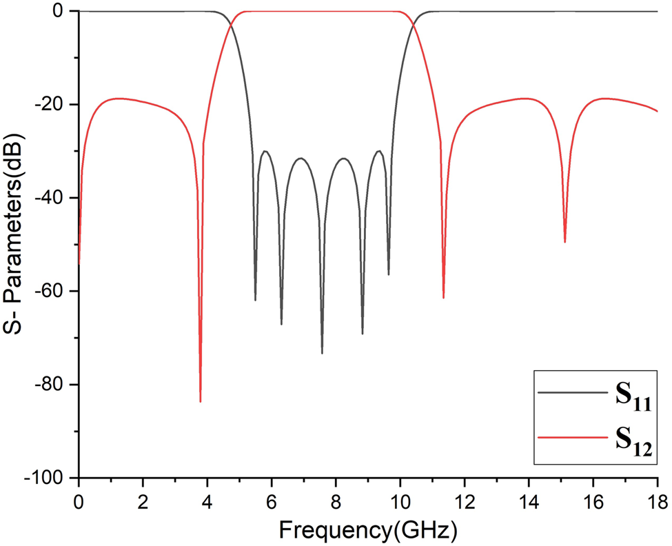
The S-parameter response of ideal design topology, as depicted in Fig. 5, shows that four TZs are achieved around the passband having five transmission poles. The detailed analysis showed that by changing the electrical length θ, the position of transmission poles could be controlled. As shown in Fig. 6, for θ = 83o, the position of TZ is at 5.49, 6.30, 7.5, 8.8, and 9.6 GHz, respectively. The TZ shifts to a lower frequency as the θ value increases. Simultaneously, by decreasing the value of θ, the TZ moves to a higher frequency.
Ideal response of proposed UWB (Z in = 36.16Ω, Z oo = 30.25Ω, Z oe = 169.1Ω, Z os = 43.94Ω, θ in = θ cl = 83.230, θ os = 2θ in).
Frequency response w.r.t θ variation.

It was also discovered that open circuit stubs play an important role in generating extra poles. Figure 7 shows that without the use of open circuit stubs, the number of poles is reduced to three, with a FBW of $64 \%$ . It was observed that incorporating open circuit stubs in the design results in two more poles and a $3 \%$
 increase in FBW.
Frequency response w.r.t open circuit stub.

Result and measurements
To validate the proposed design, a high-frequency structural simulator is used to design a microstrip filter prototype. The design topology is fabricated on Roger duroid 5880 substrates with relative dielectric constant $( \epsilon _r) = 2.20$ , dielectric loss tangent (tan δ) = 0.0009, thickness (H) = 0.787 mm, and copper thickness (T) = 0.0175 mm. The configuration of the proposed UWB design topology is depicted in Fig. 8. A line calculator, which is a free built-in tool in ADS, is used to calculate the physical dimensions from ideal design parameters (mentioned in Fig. 5). The physical dimension of microstrip lines are length (L i) and widths (W i). To achieve the best outcome, the microstrip structure is then further refined. After fine-tuning, the physical parameter values are W in = 0.98, W 1 = 0.20, W 2 = 0.67, W 3 = 1.89, W 4 = 0.94, L = 7.75, L in = 4.74, L 1 = 1.95, L 2 = 10, L 3 = 0.95, L 4 = 1.71, and S = 0.20 respectively (unit is mm). Microstrip tapered lines are used to avoid losses due to steps in the transmission line at I/0.
Configuration of proposed UWB filter.

The simulated and full-wave results are also demonstrated in Fig. 9, where good agreement between simulated and measured results is depicted. The measured result shows four transmission poles at 7.1, 7.96, 8.74, and 9.18 GHz. In addition, three TZs are achieved at 13.30, 15.27, and 16.79 GHz, respectively. The measured center frequency is 7.8 GHz with a −3 dB FBW of 47.69 $\%$ . Moreover, the measured minimum insertion is less than 0.43 dB within the whole passband. Furthermore, out-of-band rejection of greater than 39.34 dB from 10 to 18 GHz is achieved, as shown in Fig. 9. The size of the filter is 0.24λ g × 0.24λ g, where λ g is the guided wavelength at the center frequency of 7.8 GHz.
Simulated and measured result of proposed UWB.

The passband extends from 5.94 to 9.66 GHz with a return loss better than 25.35 dB and a slight difference in ripple level. Because a transmission line's behavior is dispersive, achieving a qualifying ripple level in broadband frequency response is usually difficult. Furthermore, comparing the measured frequency response to the calculated response, the substrate loss contributes to a significant insertion loss. Furthermore, fabrication tolerances, impedance matching, and parasitic effects of the SME connector may further cause differences between measured and simulated findings. Using a tapered line reduces the loss due to step transitions in the specified filter. In full-wave EM simulations, tunning and optimization are used to cater to the substrate loss. Theoretical analysis reveals that constructive interference is responsible for the generation of bandpass response.
Figure 10 shows the electrical field spectrum for the proposed UWB BPF at (a) 16.6 GHz, (b) 8.1 GHz, and (c) 2.3 GHz respectively. It is observed that at passband frequency, both paths contribute to a maximum field.
Electric field spectrum of 1st(P-I) design.

The configuration of the proposed dual BPF design along with the physical design parameters is shown in Fig. 11. Dual broadband bandpass response is generated via additional coupling and an asymmetrical stub in the primary design. As shown in Fig. 12, changing the spacing between the coupled lines will alter the number of transmission poles. More tightly coupled couple lines have more transmission poles and wider passband bandwidth, as depicted in Fig. 12(c). The physical length of coupled lines (L 2, L 3) allows the spectrum to be adjusted to higher and lower frequencies. Asymmetrical stubs are employed at both ends, resulting in two extra transmission poles and improved selectivity.
Layout of proposed dual-band bandpass filter with W 1 = 0.32, W 2 = 0.73, W 3 = 0.21, W 4 = 0.31, L 1 = 1.04, L 2 = 7.43, L 3 = 0.23, L 4 = 1.43, L 5 = 3.96, L 6 = 0.93, S 1 = 0.2, and S 2 = 0.49 (units are in mm scale).

TP's versus couple line spacing (a)0.56 (b)0.36 (c)0.23.

The dual broadband response offered by this design operates at 7.40 and 14.15 GHz, with 3 dB FBWs of 32.4 and 12.1$\%$ , respectively. As shown in Fig. 13, six transmission poles are measured at 7, 7.7, 8.3, 13.7, 14.2, and 14.8 GHz, in addition to two TZs at 10 and 17.8 GHz, respectively.
Simulated and measured response of dual-band bandpass filter.

Additionally, the measured minimum insertion is less than 0.23 dB throughout the entire passband. The first and second passband bandwidths are 2.40 and 1.7 GHz, respectively, with a return loss of less than 16.8 dB. The filter is 0.64λ g × 0.62λ g in size, where λ g denotes the guided wavelength at a center frequency of 7.40 GHz. The electric field spectrum of the dual-band BPF is shown in Fig. 14 at (a) 7.59 GHz, (b) 12.5 GHz, and (c) 14.01 GHz.
Electric field spectrum of 2nd(P-II) design.

It is noted that for the first passband, just the couple line contributes, and for the second passband, both the open stub and the coupled line contribute collectively. However, practically the entire circuit stays inactive in the bandstop region. Figure 15 depicts the measured group delay of both prototypes. In a single UWB BPF design topology, less than 0.64 ns group delay is measured in the 5.94–9.64 GHz spectrum. The measured group delay for dual-band BPF design topology is less than 0.78 ns for both passbands.
Group delay of (a) UWB and (b) dual-band BPF.

The comparison between the published literature and the proposed single UWB and dual broadband BPF designs is shown in Tables 1 and 2, respectively. It is observed that the proposed designs have high selectivity and wide stopband rejection while maintaining a compact size and good in-band insertion loss. The slight frequency shift is caused by the PCB's parasitic inductance and capacitance.
Comparison of proposed single UWB BPF (P-I) with reported filters

Comparison of proposed dual broadband BPF (P-II) with reported filters

Conclusion
An MMR-based SRR with a parallel coupled line and a step impendence open circuit stub structure is presented to accomplish single and dual-band BPF. A detailed analysis is performed to achieve the desired electrical performance of the single and dual-band BPFs. Furthermore, the manufactured prototypes’ measured results have supported the proposed topologies’ theory. Moreover, both designs have a simple configuration, compactness, good insertion loss, ease of fabrication, and large upper stopband with spurious rejection. The measured and simulated results agree quite well. As a result, the topologies presented for multiband BPF are tempting for next-generation wireless communication networks.
Author contributions
Conceptualization: Bilal Mushtaq; data curation and analysis: Bilal Mushtaq; methodology: Bilal Mushtaq; resources: Bilal Mushtaq; software and visualization: Bilal Mushtaq; supervision: Sohail Khalid; writing, reviewing, and editing: Bilal Mushtaq, Sohail Khalid.
Conflict of interest
None.
 Bilal Mushtaq obtained B.S. and M.S. in electrical engineering from HITEC University, Taxila, Pakistan in 2011 and 2016 respectively. From 2012 to 2020, he worked as a lecturer in the Electrical Engineering Department at Foundation University Rawalpindi Campus in Rawalpindi, Pakistan. He has been with Riphah International University Islamabad, Pakistan, since 2021, where he is also pursuing his doctoral degree (Ph.D.). His research interests include the design and synthesis of microwave filters, secure communication, and renewable energy.
 Sohail Khalid (MIEEE) did his Bachelor's degree in electrical engineering (Hons. First-Class) from COMSATS Islamabad, Pakistan, in 2008. His Master's degree was in wireless networks from the Queen Mary University of London in 2009. He obtained Ph.D. from Universiti Teknologi PETRONAS Malaysia in 2014. He is a professional member of the Pakistan Engineering Council. He is currently an associate professor and head of the Electrical Engineering Department at Riphah International University Islamabad, Pakistan. His research interests include the synthesis and design of RF devices. Moreover, he is also doing research in developing novel machine and deep learning algorithms/architecture for health care systems.



