I. INTRODUCTION
With the rapid development of wireless communication, the multi-frequencies antenna which can cover multiple bands for different communication systems has become one of the most important devices. The wireless local area network (WLAN) standards of 2.4–2.484 GHz (IEEE 802.11b/g)/5.15–5.825 GHz (IEEE 802.11a) and the worldwide interoperability for microwave access (WiMAX) standards of 2.5–2.69/3.4–3.69/5.25–5.85 GHz and radio frequency identification (RFID) standards of 2.45/5.8 GHz are the most popular systems in recent years. In order to satisfy these systems simultaneously, multi-band antennas with large impedance bandwidth and excellent radiation performance have been designed. Because of low cost, light weight, and good radiation characteristics, the printed monopole antennas have been widely used in wireless communication terminals. Recently, the printed monopole antennas with different schemes for WLAN applications or suitable for the applications of both WLAN and WiMAX communication systems have been reported [Reference Liu, Wu and Chu1–Reference Thomas and Sreenivasan8]. The handheld RFID reader antenna also has been designed and reported in a few letters [Reference Yang, Yin, Hu and Zhao9, Reference Mobashsher and Aldhaheri10]. For example, the coplanar waveguide (CPW)-fed monopole antenna by embedding different type slots into the metal patch for WLAN-bands applications was presented [Reference Liu, Wu and Chu1]. The symmetrical L-strips and square-slot antenna was proposed to realize multiband functions [Reference Zhai, Ma, Han and Liang4]. A triple-band antenna with three simple circular-arc-shaped strips was created for WiMAX and WLAN applications [Reference Pei, Wang, Gao and Leng5]. A miniaturized multi-frequency antenna with circular ring and Y-shape-like strip was presented for WiMAX and WLAN operation [Reference Pei, Wang, Gao and Leng5]. Although the above antennas have many advantages, there are still some performances to be improved. For example, only two-bands operations were realized in [Reference Zhai, Ma, Han and Liang4, Reference Yang, Yin, Hu and Zhao9], and only RFID application was mentioned in [Reference Mobashsher and Aldhaheri10], which limited the functions and work modes in portable devices. The whole dimensions of antennas are large three-dimensional size in [Reference Huang and Yu11], which possibly limit the integration size of the wireless communication devices and impact the portable characteristics.
In this paper a novel compact planar tri-band CPW-feed antenna for WLAN/WiMAX/RFID applications is proposed. The proposed antenna consists of a metal radiation element with four different long strips and a multi-triangular structure as metal ground plane. These two structures are printed on the same side of a substrate and the antenna is fed by a CPW-feed line. By carefully tuning the locations and the sizes of these four strips, the antenna can yield three different resonating frequencies to cover the desired bands for WLAN/WiMAX/RFID communication applications. The simulated and experimental results demonstrate that the proposed antenna has the impedance bandwidth (for return loss less than −10 dB) of 700 MHz (2.2–2.9 GHz), 540 MHz (3.16–3.7 GHz), and 850 MHz (5.05–5.9 GHz), which can cover the WLAN 2.4/5.8 GHz bands, the WiMAX 2.5/3.5 GHz bands, and the RFID 2.45/5.8 GHz bands.
II. ANTENNA DESIGN
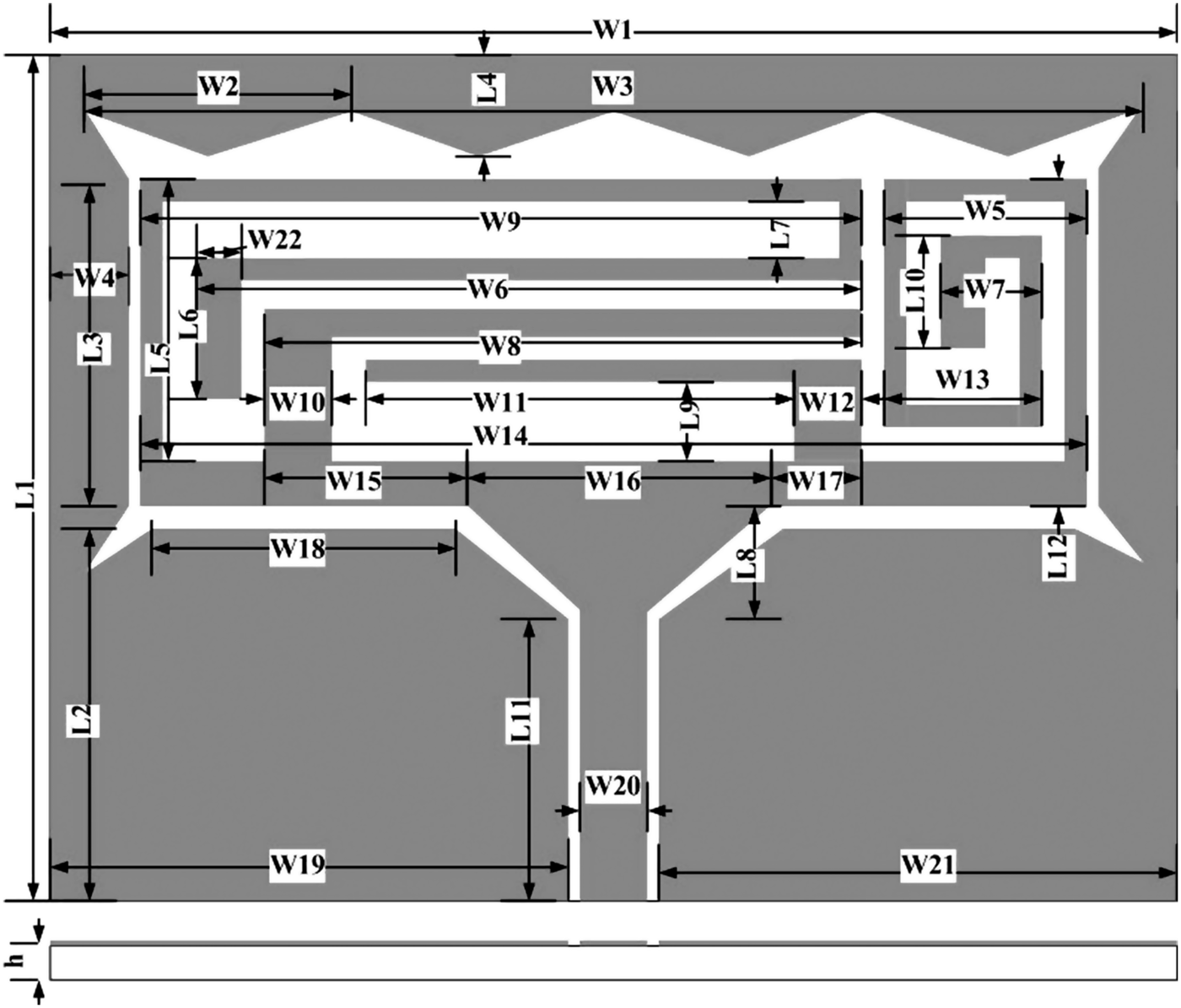
The configuration of the proposed compact planar tri-band CPW-fed antenna is shown in Fig. 1. The substrate of the proposed antenna is FR4 with relative permittivity 4.4, the thickness of the substrate is h = 1.0 mm and loss tangent is 0.018. The dimensions of the tri-band antenna are 30 mm × 44 mm.
Configuration of the proposed antenna.

The proposed antenna is composed of a multi-triangular structure as metal ground plane which has four ladder-shaped patches and four triangular patches, the rectangular metal patch as a CPW-feed line connects to the metal radiation element with four different size strips. These structures are printed on the same side of the FR-4 substrate. All of the mechanisms are exhibited at the top view of the fabricated antenna in Fig. 2. The structure of the multi-triangular ground plane can impact impedance bandwidth of the proposed antenna. By tuning length and the sizes of these four strips seriously, the antenna has obtained three different resonating frequencies which can cover the desired bands for WLAN/WiMAX/RFID communication applications. The 50 Ω micro strip CPW-feed line connects to a SMA connector and the width of the feed line is W20 = 2.8 mm.
The top view of the fabricated antenna.
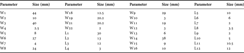
The full wave analysis software Ansoft HFSS is utilized in analyzing the performance and refining the geometry of the proposed antenna. The optimized dimensions of the proposed antenna are shown in Table 1 and Fig. 2 is the photograph of the proposed prototype. The proposed antenna can effectively achieve three radiation bands by HFSS simulation for WLAN/WiMAX/RFID communication applications.
Parameters of the proposed antenna.
III. SIMULATION AND MEASUREMENT RESULTS
Based on the detailed dimensions given in Table 1, the proposed antenna is constructed and measured using Agilent N5244A vector network analyzer. Figure 3 shows that the simulated impedance bandwidth of the proposed antenna (Ant1). The simulated impedance bandwidth (for return loss less than −10 dB) is reaching 700 MHz (2.2–2.9 GHz), 540 MHz (3.16–3.7 GHz), and 850 MHz (5.05–5.9 GHz), simultaneously. In order to examine the function of the four different strips which connect to the triangular metal-feed line, the simulated return losses for the four cases which have different strips as radiation element are shown in Fig. 3. There are two resonating frequencies for the design of Ant2 denoted by the red line. For Ant3, as the blue line shown, larger impedance bandwidth can be achieved at 2.4 and 2.8 GHz, but only cover one communication frequency range. As the design of the Ant4 shown, there are also two resonating frequencies at 3.5 and 5.7 GHz which are different from the 2.4 and 3.9 GHz of the Ant2. Obviously, by merging Ant2 with Ant4, three resonating frequencies are produced which can cover 2.2–2.9, 3.16–3.7, and 5.05–5.9 GHz and larger impedance bandwidth is achieved as shown in Ant1.
Simulated impedance bandwidth of the proposed antenna.
Figure 4 shows that the results of the simulation and the measurement agree with each other very well. The proposed antenna can achieve the impedance bandwidth (for return loss less than −10 dB) of 700 MHz (2.2–2.9 GHz), 540 MHz (3.16–3.7 GHz), and 850 MHz (5.05–5.9 GHz), which can cover the WLAN 2.4/5.8 GHz bands, the WiMAX 2.5/3.5 GHz bands, and the RFID 2.45/5.8 GHz bands. Figure 5 denotes the simulated impedance of the proposed antenna at three different resonating frequencies. It shows that the impedance of the proposed antenna matches well at three resonating frequencies. In order to further study the function of four strips of the proposed antenna, surface currents of the whole proposed antenna at different resonating frequencies are shown in Fig. 6.
Measured and simulated impedance bandwidth for the proposed antenna.
The impedance graph for the proposed antenna.
Simulated surface current distribution at 2.4, 3.4, and 5.2 GHz.
By contrast, we can see that the surface current distributions are concentrated between different strips when the resonances are changed to different frequencies. In Fig. 6(a), the surface currents are stronger between the left (1) strip and left (2) strip at 2.4 GHz. In Fig. 6(b), the surface currents at 3.4 GHz distribute around the left (2) and the left (3) strips. From the Fig. 6(c), it is observed that the surface currents are concentrated along the left (2) and left (4) strips at 5.2 GHz. This indicates that the four different strips can yield three resonating frequencies, and the excited impedance bandwidth has been largely improved at these three frequency ranges.
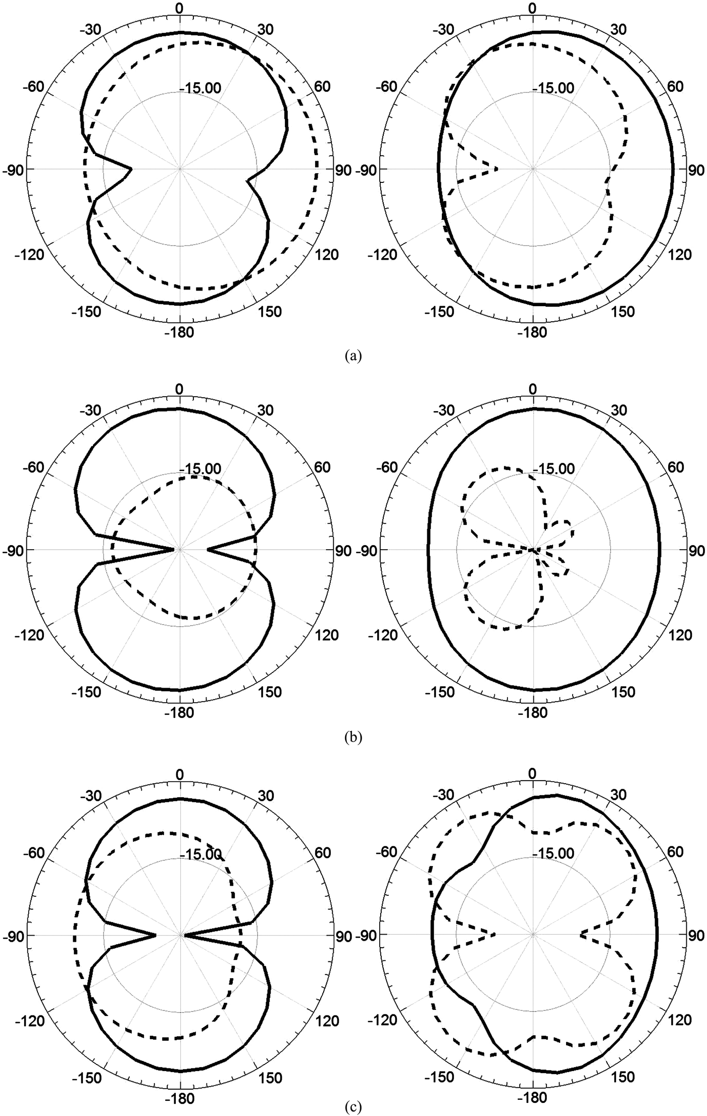
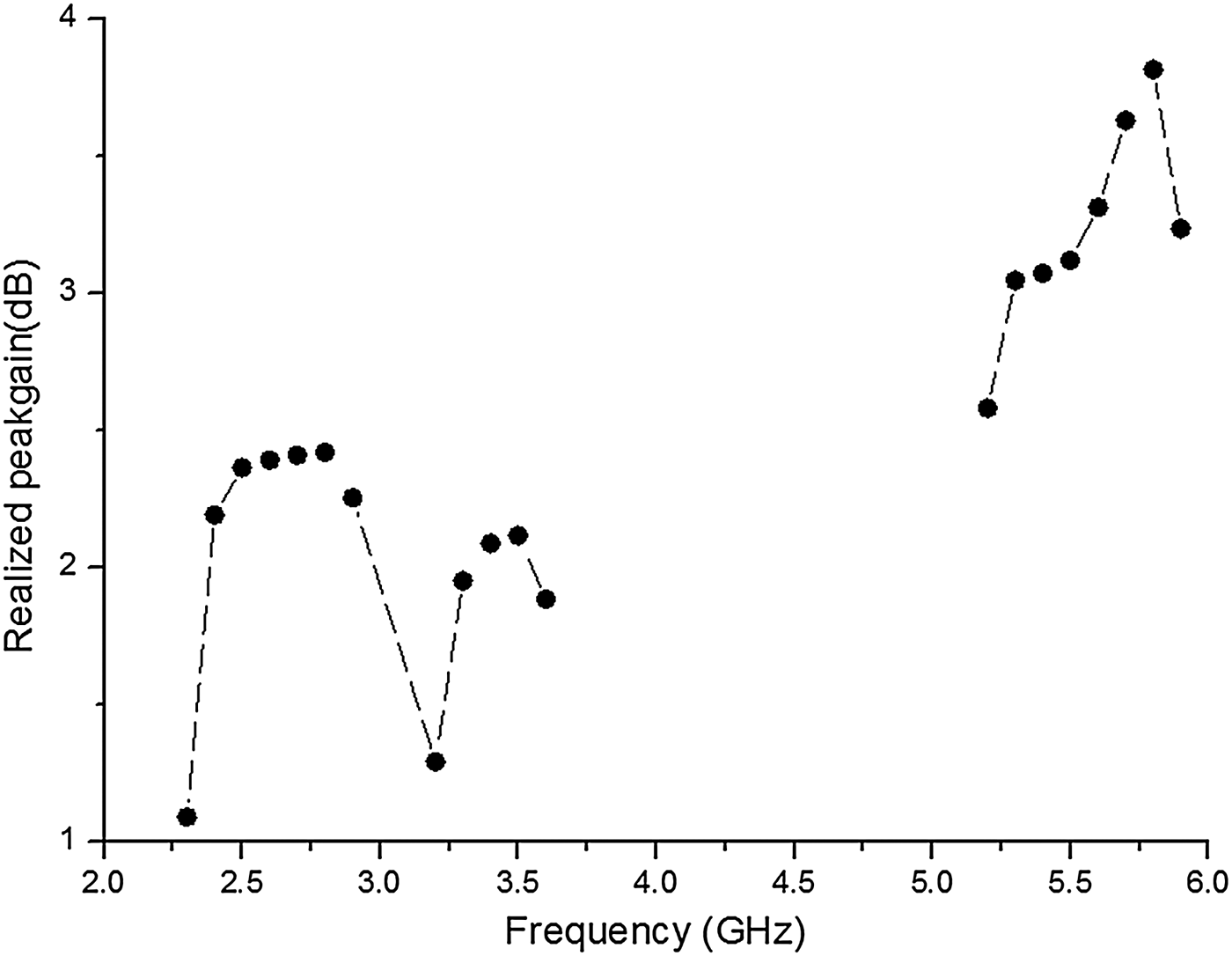
The simulated far field radiation characteristics at these frequencies of 2.4, 3.4, and 5.2 GHz are shown in Fig. 7. The co-polarization and cross-polarization in the x–z (phi = 0) and y–z (phi = 90) planes are given. Obviously, the proposed antenna has an approximately omnidirectional radiation patterns at lower frequencies. However, the omnidirectional radiation characteristics deteriorate with the frequency increases. This may due to the multi-triangular metal ground plane impacts the current distributions at higher frequencies. The peak-gain of the proposed antenna is shown in Fig. 8. Obviously, the peak-gain varies from 1.09 to 2.45 dB at the lower communication band of 2.3–3.7 GHz, and from 5.05 to 5.9 GHz, the proposed tri-band antenna can maintain the peak-gain between 2.58 and 3.82 dB. As the design is not perfect enough when improving the impedance bandwidth, the gain of the proposed antenna has reduced relatively, but the proposed antenna still has stable gain, and it is a good candidate for the WLAN/WiMAX/RFID operations.
Far-field radiation patterns for proposed antenna at (a) 2.4, (b) 3.4, and (c) 5.2 GHz.
Peak gain of the proposed antenna against frequency.
IV. CONCLUSION
A novel compact planar tri-band CPW-feed antenna for WLAN/WiMAX/RFID applications is proposed. The proposed antenna consists of a metal radiation element with four different long strips and multi-triangular metal ground plane. By carefully tuning the locations and the sizes of these four strips, the antenna can obtain three different resonating frequencies to cover the desired bands for WLAN/WiMAX/RFID communication applications. The simulated and experimental results demonstrate that the proposed antenna has the impedance bandwidth of 700 MHz (2.2–2.9 GHz), 540 MHz (3.16–3.7 GHz), and 850 MHz (5.05–5.9 GHz). These results show that the tri-band antenna can cover the WLAN 2.4/5.8 GHz band, the WiMAX 2.5/3.5 GHz bands, and the RFID 2.45/5.8 GHz bands. Therefore, the proposed antenna is suitable for WLAN/WiMAX/RFID communication applications.