

Introduction
Farm Management Information Systems (FMISs) have been rapidly evolving in the last few years, advancing from simple data handling tools to complex systems with real-time agricultural machinery fleet management and decision support functionalities (Sørensen et al., Reference Sørensen, Pesonen, Bochtis, Vougioukas and Suomi2011; Fountas et al., Reference Fountas, Carli, Sørensen, Tsiropoulos, Cavalaris and Vatsanidou2015). In order to extract useful information from an FMIS, all information related to agricultural tasks need to be properly recorded by the operator, and then manually imported into the FMIS. A common problem with FMISs is that the necessary information associated with agricultural tasks are not properly recorded, and in some cases are fragmented with many missing parts. Furthermore, the farmer is often reluctant to devote the necessary time to aggregate all logged information into agricultural tasks and import them into the FMIS (Paraforos et al., Reference Paraforos, Vassiliadis, Kortenbruck, Stamkopoulos, Ziogas and Sapounas2016b).
Various types of FMISs have emerged the last years. Some solutions provided by researchers involve tractor-implement draft forces (Tsiropoulos et al., Reference Tsiropoulos, Fountas, Gemtos, Gravalos and Paraforos2013), and hand harvested crops (Ampatzidis et al., Reference Ampatzidis, Tan, Haley and Whiting2016). Nikkilä et al. (Reference Nikkilä, Seilonen and Koskinen2010) presented an FMIS with an emphasis on precision agriculture. A number of commercial solutions are also available, such as Farmtune (www.farmtune.com), FarmWorks (www.farmworks.com), and 365FarmNet (www.365farmnet.com), just to name a few.
Recent trends include enhancing functionality of the FMIS using machine data, as agricultural machines produce a large amount of data as they operate (Fountas et al., Reference Fountas, Carli, Sørensen, Tsiropoulos, Cavalaris and Vatsanidou2015). These data come from various sensors and electronic control units that are installed on these machines, and are intended for the correct operation but also for the real-time communication among different machines. Steinberger et al. (Reference Steinberger, Rothmund and Auernhammer2009) introduced a methodology for acquiring agricultural process data from ISO 11783 (ISOBUS), which were sent to a server for further analysis and subsequent task formulation. Remote access of ISOBUS data was also performed by Oksanen et al. (Reference Oksanen, Piirainen and Seilonen2015).
Commercial solutions using machine data for agricultural machinery fleet management already exist, such as CLAAS Telematics, John Deere JDLink, AGCO AgCommand, and New Holland PLM Connect. Nevertheless, usually the support is limited to the same brand or partner companies machinery (Oksanen et al., Reference Oksanen, Piirainen and Seilonen2015). The connection of ISOBUS with an FMIS is described in detail in ISO 11783-10 (Anon., 2015). At the moment ISOBUS is not available on all agricultural machinery, but SAE J1939 has been implemented on almost all tractors produced in the last decade.
The aim of this study is to automate the process of importing task-related data into an FMIS, focusing mainly on small and medium size farms, whose machinery fleet is not so advanced. By recording a tractor’s CAN-Bus ISO 11783 (if available) and SAE J1939 communication information using a data logger, the information that farmers usually import into an FMIS could be automatically acquired, analysed, and later aggregated into specific agricultural tasks. This will save valuable time for the farmer, and will also result in a more reliable and detailed task reporting in the FMIS. The data logger should have connectivity with the FMIS’s cloud-based computer using machine to machine communication; thus, limiting human contribution.
Materials and Methods
The developed FMIS
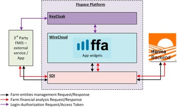
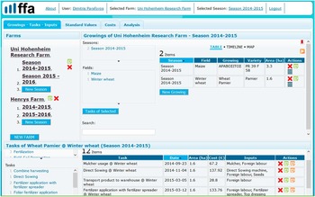
A cloud based FMIS, called ifarma (ifarma.agrostis.gr), has been developed by Agrostis Agricultural Information Systems (Thessaloniki, Greece). In addition to ifarma, a farm financial analysis (ffa) tool was developed using the backend of ifarma and was based on Future Internet (FI) technologies (www.fi-ppp.eu). The combined ifarma-ffa system architecture and the information exchange is depicted in Figure 1. The graphical user interface of the FMIS is illustrated in Figure 2. The section areas that are visible on the initial tab are Farms, Growings that belong to a specific farm, and Tasks that were performed on each growing crop. More information regarding the structure and the functionality of the ifarma-ffa FMIS can be found by Paraforos et al. (Reference Paraforos, Vassiliadis, Kortenbruck, Stamkopoulos, Ziogas and Sapounas2016b).
Architecture and information exchange of ifarma-ffa using FI technologies (Paraforos et al., Reference Paraforos, Vassiliadis, Kortenbruck, Stamkopoulos, Ziogas and Sapounas2016b).

Graphical user interface of ifarma-ffa FMIS.

Instrumentation
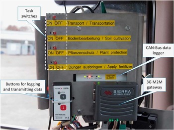
A metal construction was developed in order to mount all the necessary instrumentation (Figure 3), and was placed on a 6210 R 156.6 kW tractor (John Deere, Moline, Illinois, United States). A GL2000 CAN-Bus data logger (Vector Informatik GmbH, Stuttgart, Germany) was connected to the CAN-Bus diagnostic interface, to record J1939 and ISOBUS communication data. The logged data were stored on a 2GB SDHC card, which was possible to be increased up to 32 GB. Nevertheless, the storage capacity of the card was more important when the data were not being transmitted and the operator had to eject the memory card and manually transfer the data to the farm PC. The acquired data were georeferenced as the logger was also recording absolute positioning data from a Navilock NL-603P differential global navigation satellite system (DGNSS) receiver (Tragant Handels- und Beteiligungs GmbH, Berlin, Germany).
Utilised instrumentation for CAN-Bus communication data acquisition.

The tractor operator was given the ability to choose the current operating mode among four possible modes (i.e. transportation, soil cultivation, plant protection, and fertiliser application) by switches, which were connected to an equal number of digital inputs of the data logger. To wirelessly transmit the data to the cloud-based server of the FMIS, the logger was connected with a 3 G M2M (Machine to Machine) gateway (Sierra Wireless, Richmond, BC, Canada) with an installed SIM card. The operator could start the logging of data by pressing button 1 of the E2T2L module (Vector Informatik GmbH, Stuttgart, Germany) as illustrated in the bottom left corner of Figure 3. Data logging was stopped as soon as the operator would press button 2.
Data acquisition
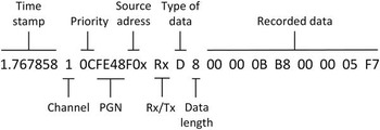
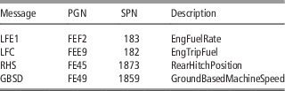
The GL2000 was configured using its own configuration tool to filter the tractor’s CAN-Bus communication data, and record only the messages with specific CAN-IDs. The messages were filtered according to their parameter group number (PGN). It was configured only once, without requiring any further action by the tractor operator. An example of a CAN-Bus message as it was retrieved from the data logger is presented in Figure 4. If one of the desired PGNs was detected, all the machine parameters based on the suspect parameter number (SPN) that were contained in the message, were read. All the messages that were recorded by the data logger are presented in Table 1.
An example of a CAN-Bus message as retrieved from the data logger.

Recorded messages by the data logger

Cloud system
At the same time the logging was stopped, the data were transmitted to the remote server using the M2M gateway. At the remote server, where the FMIS was also running, the ML (Multi Logger) Server software (G.i.N. – Gesellschaft für industrielle Netzwerke mbH, Griesheim, Germany) was responsible for receiving the data. Logged CAN-Bus messages were saved in batches in ASCII files with one message per row as indicated in Figure 4. A web service developed with SWI Prolog (www.swi-prolog.org) was also running on the server and was listening for requests on HTTP port (80). It was parsing the ASCII files using Prolog rules in a manner similar to DCG (Definite Clause Grammar) (Pereira and Waren, Reference Pereira and Warren1980). The service was run to parse the messages one by one until it reached a “start” message, which meant that one switch was set to ON. In that case, a new “grammar” rule was triggered, which was collecting all subsequent messages into an intermediate structure until an “end” message was received (switch set to OFF). This intermediate structure was then processed to generate task files in JSON format. The type of the task (fertilization, transportation, etc.) was determined by the starting message depending on which switch was set to ON, while the other task properties such as duration and fuel consumption were calculated from the content of the intermediate structure. The service was also responsible for importing the resulted tasks into the FMIS database.
Experiments
Experimental data were acquired during transportation and while ploughing with a mounted mouldboard plough. The satellite view of the area where the experiments took place is illustrated in Figure 5. In the same figure, the route that was followed by the tractor can be seen for both operating modes (i.e. transportation and ploughing). A closer view of one of the fields and the tractor’s route during ploughing is also indicated.
Satellite view of the area where the experiments took place. The followed route by the tractor and a closer view of the field where ploughing was performed are also indicated.

Results and Discussion
An example of a created task on the FMIS for the field highlighted in the zoom area of Figure 5, after acquiring and analysing the CAN-Bus data, is presented in Figure 6. The first and second column include the description and the date of the performed task, respectively. The field Cost was calculated according to the following two steps: first, the total fuel consumption (number of litres) for the specific tasks, as this was extracted from the CAN-Bus data, was multiplied with the value that the user had imported for fuel price; second, this resulted value was multiplied with a factor (also imported by the farmer), which was defining the total operating cost of the specific task, as this simplified calculation method is performed from a large number of farmers with a small sized farm, i.e. to multiply the fuel cost with a fixed constant, to define the total operating cost of a specific task (de Jong, Reference de Jong1997). For the purpose of this work, this factor was equal to two for ploughing, while for each task it was possible to import a different factor. It can be observed that in Figure 6 the Inputs field was empty. The user could leave this field as it was, and rely on the calculations of the described procedure, or could add various inputs by clicking on the appropriate button under the field Actions. These inputs could include for example labour cost and machine cost or even cost of seeds, fertilisers, pesticides, etc.
Created task on the FMIS based on the acquired CAN-Bus data.

The user had the possibility to present various information acquired from the CAN-Bus data related to each specific task. An example can be seen in Figure 7a, and 7b, where the time-series of the total fuel consumption and the engine fuel rate are presented, respectively. Since all data were georeferenced using the DGNSS, it was possible to illustrate a spatial representation of the acquired data. An example is illustrated in Figure 8, where the engine fuel rate while ploughing is presented. It can be seen that during headland turning, when the plough was not in the soil, the fuel consumption was reduced (as expected), while during the infield parallel paths this reached up to 45 L h–1. This information was important for the farmer on helping him increase the efficiency of the performed operation and optimise fuel consumption during normal agricultural tasks.
(a) Total fuel consumption and (b) engine fuel rate during ploughing.

Spatial representation of the engine fuel rate during ploughing.

Conclusions
Machine communication data were collected, analysed, and aggregated into agricultural tasks. The developed methodology managed to reduce the manual data treatment for importing task-related data into the FMIS, a process which is error-prone and time-consuming. The FMIS presented the performed tasks to the user, giving the possibility to further process them. Furthermore, data that for the farmer was difficult to record, e.g. engine fuel rate, became automatically available to the FMIS for further processing. In this work, the operator could choose the current operation only out of four available tasks. The number of these available tasks could be increased up to 16 if a combination of all switches was used. Except the farmers that use FMISs, the recorded time and task-related characteristics from a big number of machines are very important also for the machine developers. This information can help them provide more targeted maintenance contracts to their customers but also develop more realistic accelerated testing scenarios that correspond to real-life conditions (Paraforos et al., Reference Paraforos, Griepentrog and Vougioukas2016a).
Future work should involve the transformation of the acquired ISOBUS communication data to an XML-based file as described in the Task Controller of ISO 11783-10 (Anon., 2015). In this way the developed FMIS could be used for precision agriculture purposes by creating and sending a task file to the implement. In this work, the operator had to choose the type of the performed task by selecting the appropriate switch. This process can also be automated by developing an algorithm, which after analysing the acquired CAN-Bus and GNSS data would be able to provide the type of the task that was performed. Furthermore, the cost calculation of the performed tasks could be further elaborated, in order to perform a more detailed calculation of the cost of each task.
Acknowledgments
This work was financially supported by the German Federal Ministry of Food and Agriculture (BMEL) through the Federal Office for Agriculture and Food (BLE), grant number 2815ERA01H. This project was also funded by SmartAgriFood (Smart Food and Agribusiness, Future Internet for Safe and Healthy Food from Farm to Fork) under the FI.ICT-2011.1.8 Work Programme. The authors would like to thank Christian Schwarze for his help with installing and configuring the data logger.