


I. INTRODUCTION
The applications of satellite-based location techniques will provide more reliable services in the future given the fact of proper spectrum utilization [Reference Valenta, Marsalek, Baudoin, Villegas, Suarez and Robert1]. These services will be related to various emergency alarms for security and health reasons, and to more accurate navigation systems to be implemented in cars, mobile phones, terminals, and other devices [Reference Masson and Monnerat2]. The previous features will be integrated in the Galileo system. Specifically, these will be part of the Open Service, the Public Regulated Service, the Search and Rescue Service, and the Safety-of-Life and Commercial Service. All services should have been launched when Galileo will finally be consisting of its nominal value of 30 satellites [Reference Gibbons3, Reference Moudrak, Konovaltsev, Denks and Hammesfahr4].
If multibeam antennas [Reference Chronopoulos, Koliopanos, Angelis and Koumasis5] are implemented in the previous satellite system, then a continuous coverage over various locations on Earth's surface will be provided, along with the capability of maximizing the lowest gain levels in the regions of interest. Generally, many methods have been proposed relevant to design, simulation, and construction of multibeam antennas and its applications. They include multibeam antennas for business services with or without frequency reuse [Reference Claydon, Dinwiddy and Adatia6], development of multibeam antennas based on Luneberg lenses [Reference Kuroda, Kimura, Imai, Ishibashi, Kishimoto, Sakamoto, Uenishi, Iwai and Nakagawa7], array pattern synthesis of multibeam antennas [Reference Guenad, Meriah and Bendimerad8], search and rescue antennas [Reference Montero, Celemin and Torre9], trade-off study on array-fed reflector antennas for high beam class, etc.
This research work combines previous studies of the basic orbit elements of Galileo's constellation, with the goal of discovering the characteristics of a multibeam antenna that can be implemented in such systems and in parallel without inserting degradation in terms of coverage, interference, and frequency reuse. Also, special care is taken in exploring, by means of extended simulations, the appropriate position pattern for each of the 61 beams of the selected type of antenna, by taking into account the edge of coverage (EoC) gain because the latter has tremendous impact on satellite coverage [Reference Chronopoulos, Angelis, Koumasis and Drakou10–Reference Ruggerini, Toso and Angeletti12], interference, and frequency reuse [Reference Llombart, Neto, Gerini, Bonnedal and De Maagt13]. The purpose of this article consists in focusing on the main improvements in the design of such a type of antenna and consequent simulation results.
The rest of the paper is organized as follows. In Section II, the overview of the system under simulation is given where the key features of the simulated system are reported along with all losses that have to be implemented in the scenario for acquiring results based on real-world conditions. In Section III, a multibeam antenna's characteristics are presented and the position pattern of its multiple spot beams. In Section IV, simulations are analyzed and discussed in terms of satellite accessing, BER, and antenna gain versus elevation. Finally, conclusions along with future research goals are presented along with the future scope.
II. THE SIMULATION SYSTEM
The satellite system that was used as a basis for the simulations has been already presented and analyzed in a previous publication involving Galileo's constellation parameters [Reference Chronopoulos, Koliopanos, Pappa and Angelis14]. The propagator of the proposed scenario included earth oblateness that caused secular variations in the elements of satellites orbits. Also, major elements that described this propagator were used such as inclination, true anomaly Right Ascension of the Ascending Node (RAAN), argument of perigee and apogee, etc [Reference Brouwer15–17]. Inclination is the angle between the inertial Z-axis and the angular momentum vector where the last is perpendicular to the plane of the orbit. Its value for all satellites was equal to 56°. True anomaly is the angle from the eccentricity vector to the object position vector that is calculated according to the direction of object's motion. The latest element ranged from 0° to 348°. Also, argument of perigee is the angle from the ascending node to the lowest orbit point, which is computed in the direction of the satellite's motion. For all satellites, this element had the value of 317°. RAAN ranged from 66° to 306° and it is described by the angle from inertial X-axis to the ascending node. Ascending node is a point of the satellite's orbit (moving from south to north) when passing through the inertial equator. Generally, right ascension is measured as a rotation about Z-axis (right-handed). Finally, apogee and perigee altitude were equal to 23 616 km.
The modulation used in transmitter's and receiver's part was binary offset carrier (BOC) and the carrier frequencies were specified according to regulations of L1 and E5 bands [Reference Grein, Olynik and Clayton18, Reference Yoo, Yoo, Ahn, Yoon and Kim19]. Moreover, chip and data rates are mentioned in [Reference Chronopoulos, Koliopanos, Pappa and Angelis14, Reference Detratti, Lopez, Perez and Palacio20, Reference Sand, Mensing, Ancha and Bell21]. Also, various severe losses were taken into consideration for customizing scenario to meet the strictest specifications and they are presented in [Reference Hein, Irsigler and Avila-Rodriguez22]. The previous losses include free space path loss, ionospheric and tropospheric path delay, amplitude and phase scintillation, ionospheric refraction and Doppler shift, foliage attenuation, worst case scenario for attenuation by water vapor and oxygen, and worst case scenario for rainfall, clouds, and fog attenuation. The scenario losses had a nominal value of 189.3 dB plus an additional inserted margin of 20 dB for accounting other types of system's drawbacks concluding to a final value of 209.3 dB of signal attenuation. Each antenna's beam simulated with a power of 0.20164 dBW contributing to a total power of 12.30004 dBW (for all 61 produced beams), which was the nominal value of Effective Isotropic Radiated Power (EIRP) mentioned by Hein [Reference Hein, Irsigler and Avila-Rodriguez22]. Also, all receivers were simulated with sensitivity levels of −144 dBm [Reference Detratti, Lopez, Perez and Palacio20]. Antenna's characteristics are analytically reported in the following section.
III. THE PROPOSED MULTIBEAM ANTENNA
A large number of organizations, scientific institutions, industries, and private operators are working on the implementation of various projects such as high gain multibeam antennas [Reference Caille, Cailloce, Demolder and Bekaert23–Reference Lee, Choi, Kim and Oh25] and high-beam-class antennas [Reference Fujino, Hamamoto, Miura, Suzuki, Yamamoto, Inasawa, Naito, Konishi and Natori26], for providing state-of-the-art satellite services. These services are based on high data rate communications. Consequently, as the Galileo constellation system is a very promising project and must include in its capabilities all previous high-end techniques for being compliant if needed, with future integration of innovative applications. Specifically, by implementing multibeam antennas in this system a continuous coverage will be imminent in all desirable locations that will be covered by high quality services. Conforming to all previous researches and demands, we introduced in the simulation scenario a multibeam antenna in each of the 30 satellites of Galileo's constellation. The specifications of the proposed antenna are presented in Table 1.
Multibeam antenna design parameters for the frequency of 1.575 42 GHz.

Designing the coverage pattern of a multibeam antenna system is not always an easy task. Mayhan [Reference Mayhan and Ricardi27] and Guenad [Reference Guenad, Meriah and Bendimerad8] addressed this problem with a hexagonal shape providing satisfying earth coverage. These techniques were taken into consideration in the simulation scenario concluding to a total of 61-spot beams.
In order to synthesize the antenna pattern a variational method that is proposed in [Reference Guenad, Meriah and Bendimerad8], for 19-spot beams, was used. In the proposed multibeam antenna deployment we stepped forward, first by extending the number of the spot beams to 61, in order to provide higher data rates and quality of services, and second by taking into account the fact of EoC gain. In a hexagonal lattice, as the proposed one, EoC is defined as the cross over between three adjacent beams [Reference Llombart, Neto, Gerini, Bonnedal and De Maagt13]:
 $$G_{EoC}=G\left({\Delta \theta /\sqrt 3 } \right)$$
Taking into account the EoC is important since it is a frequency-dependent parameter and strongly affects the overall performance of multibeam systems and consequently the coverage. The value of 3 dB had to be taken into account as a typical decrease of signal power in EoC. For this purpose, the contour diameters that had to be processed in the simulation scenario were ranged from 30 to 34 dB (with an additional 1 dB margin for being absolutely sure that the design complied with the literature). Finally, only the maximum diameters of contours are presented as the absolute maximum coverage limit of each beam.
The modified theoretical multibeam antenna pattern is shown in Fig. 1 described with Euler A and B angles. In this figure, Euler A is expressed as the angle measured clockwise from 0° (vertical axis) and Euler B is the angle measured as the distance from the center of J0 to the center of each of the spot beams.
Pattern of multibeam antenna is split into eight groups. Each group can be derived from two primary groups named J and A. Notice that the second and third letter of each element of other groups corresponds to a primary spot beam from which it can be produced.

The minimum Euler B angle was found to be equal to 3.2° (e.g. distance from center of J0 to center of J1 is equal to 3.2). A1, A5, A8, and A10 have the same B angles corresponding to J1, J2, J3, and J4 elements as they are produced from J group through 60° of rotation. Moreover, the following equations are presented relevant to the elements A1, A2, A3, A4, and J0, J1, J2, J3, J4:
 $$BJ_i=3.2i\comma \; \quad {\rm for}\; i=0\comma \; 1\comma \; 2\comma \; 3\comma \; 4 -$$
 $$BA_i=\sqrt {\left[{\lpar i - 1\rpar a+\displaystyle{a \over 2}} \right]^2+\displaystyle{{3a^2 } \over 4}\comma \; } \quad {\rm for}\; i=0\comma \; 1\comma \; 2\comma \; 3\comma \; 4\quad {\rm and}\; a = 3.2^\circ$$
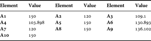
Also, it must be mentioned that Euler B angles for A6 and A9 are: A6 = A3 and A9 = A4 due to symmetry. For element A7, Euler B can be found easily as  $BA_7 = 2a \sqrt{3}$, where a is equal to 3.2°. All other values of elements which are shown in Fig. 1, have one of the already computed ones. For example, element EA5 has the same B angle with element A5 which is equal to 6.4°. Euler A angles, for group J are all equal to 90°, and for elements A1, A5, A8, and A10 equal to 150°. Using simple trigonometric functions Table 2 can be constructed. All other Euler A angles are derived from groups A and J through proper rotation. For example, Group B is the 60° rotation of sub groups A2, A3, A4, A6, A7, and A9. Finally, Euler C angle is the same for all elements and is equal to 0°.
Euler A angles for Group A (value is measured in degrees).
IV. SIMULATION RESULTS AND DISCUSSION
In the simulated scenario all the needed values were inserted and characteristics of the system were presented in Sections II and III, and then preliminary tests were conducted for satellite system integrity in simulation level. Using Giove-A [28] as the first modified satellite 2D and 3D representations of multibeam coverage were produced, which are presented in Figs 2 and 4. Afterwards, we designed various routes based on real way points. One of these routes is presented in Fig. 3, where a vehicle is moving from Bavaria to Paris through Strasbourg with a mean velocity of almost 56 km/hour.
(a) 2D radiation pattern of multibeam antenna located in Giove-A. Notice how the shapes of various spot beams vary. In order understand see Fig. 4. (b) 3D representation of the simulated Galileo system with multibeam antennas.

Route of the vehicle from Bavaria to Paris.

(a, b) 3D radiation patterns of multibeam antenna located in Giove-A. Notice the similarities between these figures (coming from simulation) and theoretical (Fig. 1).

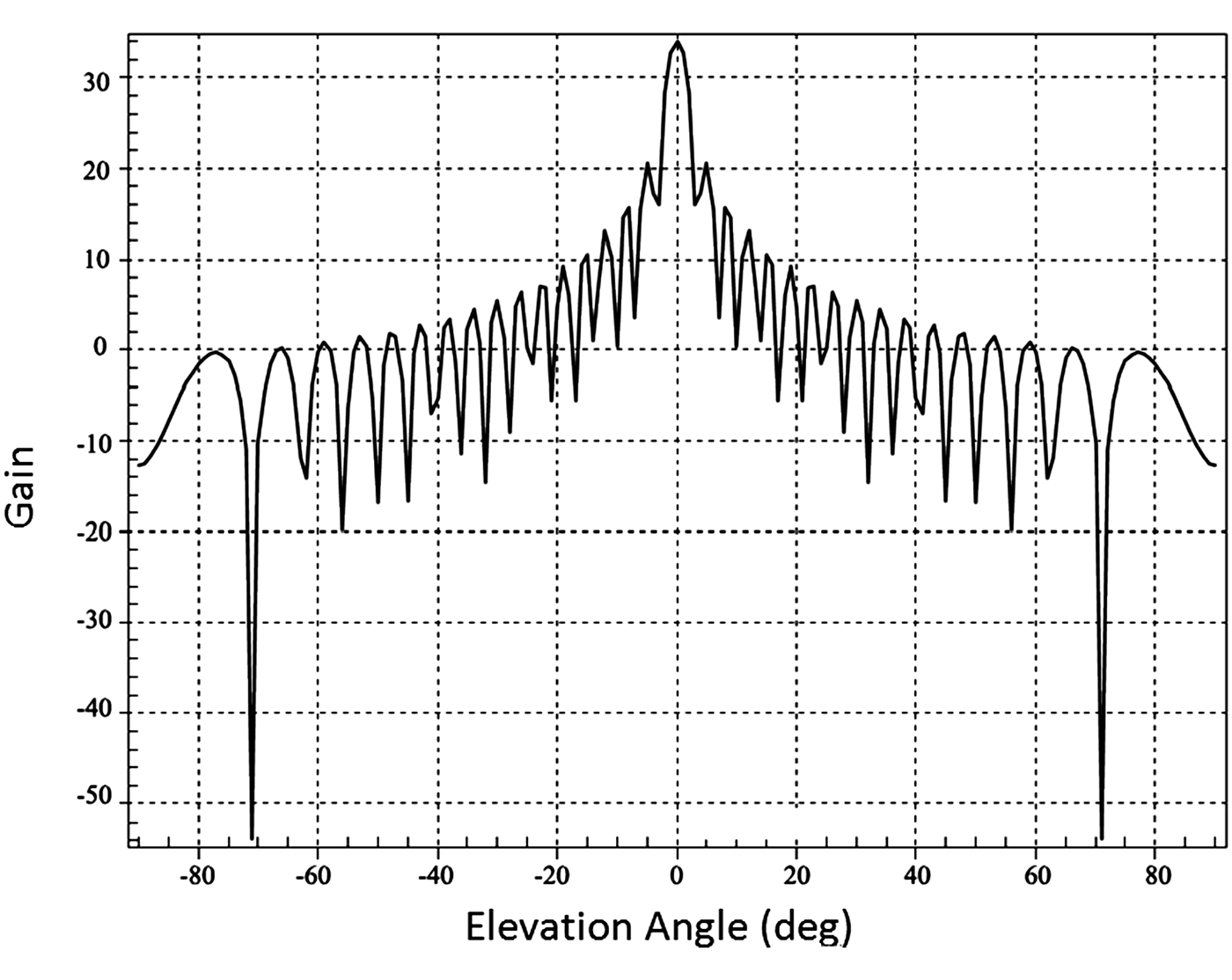
One of the main purposes was to investigate through budget analysis [17] the BER performance of the proposed system. This can be determined from Fig. 5 that even with the presence of heavy losses (209.3 dB), a BER of 0.0001 can be accomplished for Eb/No almost equal to 8.4 dB. Also, the fact must not be neglected that the Galileo system without multibeam antennas exhibited almost the same performance, but with losses of 189.3 dB. Moreover, in Fig. 6, the gain of the antenna versus elevation is presented and in Fig. 7 the time of accessing various countries using only the modified Giove-A is presented. In Fig. 8, time of accessing is shown from all satellites toward Greece. The last two simulations were needed for verifying whether satellite locking in terms of services could be sustained with multibeam antennas. These results are very satisfying confirming the good theory of operation, since it is clearly seen in Figs 7 and 8 that the coverage is acceptable and the proposed multibeam antenna overcomes the problem of flexibility in terms of coverage that is reported in [Reference Ruggerini, Toso and Angeletti12].
BER versus signal-to-noise ratio per bit, for moving vehicle (taking into consideration Galileo constellation consisted of 30 satellites).

Gain of the multibeam antenna versus elevation angle.
Time accessing related to Giove-A and various countries (for its computation all system parts and characteristics are involved such as transmitters, receivers, multibeam antennas, and orbital parameters of Giove-A).

Time accessing related to Galileo satellites and Greece (for its computation all system parts and characteristics are involved such as transmitters, receivers, multibeam antennas, and orbital parameters).

V. CONCLUSIONS
A new multibeam antenna pattern and its characteristics have been presented, for the purpose of providing continuous coverage and consequently high quality of services in various locations. Through gain analysis versus elevation, BER, and access time simulations the viability of the proposed antenna is established. Apart from the very satisfying performance results in terms of coverage, interference, and frequency reuse, the advantage of inserting multibeam antennas in a system-like Galileo, is relevant to cost and simplified procedures of designing multiple spot beams for high-end services and applications. The optimization of the antenna system is still on-going, so that further improvements of the performance are still expected.
ACKNOWLEDGEMENT
The author would like to thank AGI Inc. for the license to use STK for educational and research purposes.
 Constantinos T. Angelis was born in Arta, Greece, on May 15, 1968. He graduated from the Physics Department in the University of Ioannina, Greece in 1992, and he received his M.Sc. and Ph.D. degrees in solid-state electronics from the same university in 1996 and 2000, respectively. Today, he is a full-time Associate Professor at the Department of Informatics and Telecommunications, Technological Educational Institute of EPIRUS and a fellow researcher at the Electronics and Telecommunications Laboratory at the Physics Department of the University of Ioannina, Greece. His research interests are in the fields of electrical characterization (AC, DC, and RF) of microelectronic devices, reliability of microelectronic devices, electronic properties of semiconductor devices, electric properties of thin film semiconductor silicon transistors, effect of electric fatigue on the reliability of the above transistors, electronic low-frequency noise in semiconductor devices, RF transistor design, wireless transceiver design, radio-frequency and high-frequency wireless system design, software radio systems and digital signal processing techniques, adaptive (smart) antennas for wireless networks, array antenna beamforming, and signal propagation.



