I. INTRODUCTION
Because of the superior high specific strength and stiffness, toughness, and wear resistance, metal matrix composites with ceramic reinforcements have received much attention as potential structural materials in the wear industry primarily.Reference Tjong and Ma1–Reference Farid and Guo4 As one kind of the most widely used industrial materials, because of the potential for good wear resistance, it is worthy to develop a steel matrix composite. Among various ceramic particulates used as reinforcements such as TiC,Reference Das, Bandyopadhyay and Das5 Al2O3, SiC, TiB2, and B4C,Reference Nastasi, Kossowsky, Hirvonen and Elliott6 TiC and TiB2 particulates own the characteristics of high hardness, wettability, wear resistance, and melting temperature, resulting in the best candidate for the reinforcement of steel matrix composite. Moreover, TiB2 is relatively stable in liquid steel,Reference Telle and Petzow7 which increase its practicability in the steel matrix composite. The incorporation of TiC and TiB2 provides the better physical and mechanical properties,Reference Li, Liu, Li, Cao and He8,Reference Yang, Wang, Wang and Jiang9 which can combine the toughness of steel with the hardness of ceramic particulate to improve the wear resistance of TiC–TiB2 ceramic particulate reinforced steel matrix composite.
Currently, there are many methods to produce in situ TiC–TiB2 reinforced steel matrix composite, such as spark plasma sintering,Reference Li, Liu, Li, Cao and He8 laser cladding,Reference Du, Zou, Wang and Qu2 and conventional casting. Among these fabrication methods, combustion synthesis (CS) provides a novel method to fabricate in situ ceramic particulate reinforced steel matrix composites.Reference Zou, Shen, Cao and Jiang10 Moreover, because of easy fabrication procedures, low costs, and high product purity, the ceramic reinforcement formed in situ by CS exothermic reaction can be widely used in industrial applications. In particular, the in situ ceramic particulate reinforced steel matrix composite owns the characteristics of clean formation, ultrafine stable ceramic reinforcements,Reference Yang, Wang, Liang, Zhao and Jiang11 resulting in the perfect mechanical property for antiwear applications. CS has two ignition modes: self-propagating high-temperature synthesis (SHS) reaction is ignited by heating one end of the reactant compact and thermal explosion (TE) reaction is ignited by heating the whole reactant compact.Reference Linger, Gotman and Horvitz12 The existence of a large number of pores of CS product leads to the addition of a densification step such as hot-pressing, extrusion, quasi-isostatic pressing, and shock-wave compaction.Reference Han, Zhang and Wood13 However, the combination of CS and traditional castingReference Wang, Zhang, Wang, Ma and Jiang14–Reference Jiang, Zhao, Wang and Zhang16 has been proved feasible to produce the dense ceramic particulate reinforced steel matrix composite which possesses perfect wear resistance. The general procedures can be described as follows. The molten steel is poured into a sand mold where the reactant compacts are preplaced and fixed using locating pins.Reference Zou, Shen, Cao and Jiang10,Reference Yang, Wang, Liang, Zhao and Jiang11 The heat of the molten steel ignited the TE reaction of the compact to form ceramic particulate. Meanwhile, the steel melt infiltrates into the pores of the reacted compact, which increase the density of the compact. Using this method, the in situ ceramic locally reinforced steel matrix composite can be fabricated successfully, in which the local regions of the casting rather than the entire casting are reinforced by the relative costly particulate to achieve high wear resistance, while high toughness and strength are retained in the bulk casting, which is different from the monolithic composites.Reference Tondu, Schnick, Pawlowski, Wielage, Steinhauser and Sabatier17–Reference Daniel, Murthy and Murty20
In this study, the Mn-steel matrix composites locally reinforced with in situ TiC–TiB2 ceramic particulates from a Cu–Ti–B4C system with various B4C particulate sizes were successfully fabricated via a TE-casting route. Furthermore, the effect of B4C particle size on the reaction behaviors of the compact and wear resistance of Mn-steel matrix composite is investigated. It is expected that the experimental results could be significant in promoting the development and practical application of antiwear techniques of in situ ceramic particulate locally reinforced Mn-steel matrix composites.
II. EXPERIMENTAL PROCEDURE
The starting materials were made of commercial powders of Cu (purity: 99.5%, particle size: ∼3 μm), Ti (purity: 99.5%, particle size: ∼38 μm), and B4C (purity: 99.9%). The Cu–Ti–B4C system with a 40 wt% Cu content and molar ratio of 3:1 for Ti and B4C was investigated in this study. To investigate the effect of B4C particulate size on TE reaction behavior and wear mechanism of Mn-steel matrix composite, the particle sizes of B4C powders were ∼3.5, ∼45, and ∼150 μm, respectively. After being mixed in a stainless steel container using stainless-steel balls with the speed of 35 rpm for 8 h, the homogeneous powders were pressed into a cylindrical compact of 20 mm in diameter and 12 mm in length to obtain the green density of 65% theory density.
Before the fabrication of Mn-steel matrix composite via a TE-casting route, the reaction behavior of the compact was studied under argon atmosphere. To remove the trace of moisture, the cylindrical compact was put in a vacuum oven at about 300 °C for 3 h. The dry compact was put into a graphite die placed in an electric resistance heating furnace of 10 kW under Ar atmosphere. The compact was heated with a heating rate of 40 °C/min until TE reaction was ignited. The temperature of the center part of the compact was measured by a pair of W-Re5/W-Re26 thermocouples, which are linked up to a temperature acquisition recorder to record a temperature–time curve. After the study of reaction behavior of Cu–Ti–B4C compact, the fabrication of TiC–TiB2 ceramic particulate locally reinforced Mn-steel matrix composite was conducted. The chemical composition of the unreinforced austenite manganese steel used as a steel matrix consists of 9.09 Mn, 0.8 C, 1.39 Si, 0.01 S, 0.02 Ni, 0.06 P, and Fe as balance (all in wt%). The compacts with various B4C particulate sizes were placed in the bottom of the sand mold. Subsequently, the molten steel prepared from a 5 kg medium frequency induction furnace with a temperature of 1600 °C was poured into the sand mold and the TE reaction of Cu–Ti–B4C compact ignited by the heat of molten steel forming the composite via a TE-casting route successfully. After cooling and solidification, the composite was removed, sectioned, and polished for microstructure observation, phase identification, and dry-sliding wear test. More details about the diagrammatic sketch of the sand mold, which was used for the fabrication of Mn-steel matrix composite, are shown in our previous study.Reference Liang, Zhao, Zhang, Li and Ren21
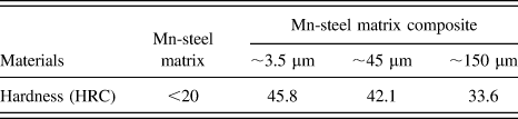
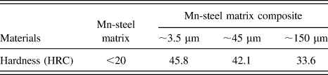
Tribological test was conducted using a pin-on-disk wear tester (model MG-2000, Zhangjiakou City, China) at room temperature in air under a relative humidity of 35%. The test pin was 6 mm in diameter and 20 mm in height. The mating disc of Φ70 mm × 15 mm was made of 4Cr5MoSiV1 (AISI H13) with a hardness of 50 ± 1 HRC and surface roughness of R a = 0.8 μm. The hardness of each pin was obtained from six individual measurements, which is shown in Table I. Each pin was polished carefully before the wear test to obtain good surface roughness. Subsequently, the pin was ultrasonically cleaned in acetone for 10 min and then dried in hot air to obtain a clean surface. To study the wear mechanism, pins with various B4C particulate sizes were conducted under the applied loads of 20, 40, 60, and 80 N, respectively. The constant sliding velocity was 0.6 m/s, and the sliding distance was 720 m. The wear mass loss of each pin was measured by an electronic balance with the resolution of 0.01 mg, and the average value for each sample was calculated using these data to evaluate the wear resistance. Microstructure was observed using scanning electron microscopy (SEM) (Model JSM-5310, JEOL Co. Ltd., Japan, Japan) together with energy-dispersive spectrometry (Model Link-Isis, Oxford, UK). The phases were identified using x-ray diffraction (XRD) (Model D/Max 2500 PC Rigaku, Tokyo, Japan).
The hardness value of steel matrix and the composites with various B4C particle sizes.
III. RESULTS AND DISCUSSION
A. Combustion characteristics and phase components of TE product
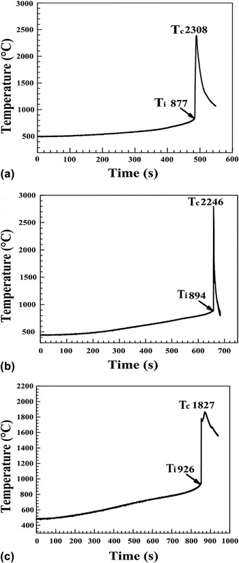
Figures 1(a)–1(c) show the temperature-time profiles for the TE reaction of the 40 wt% Cu–Ti–B4C system with various B4C particle sizes. T i represents the ignition temperature, which is the critical temperature for the ignition of TE reaction. T c represents the maximum combustion temperature, which is the maximum temperature of TE reaction. With the increase of B4C particle size, T i increased from 877 to 926 °C, and T c decreased from 2308 to 1827 °C. The temperature of molten steel was about 1538 °C, which can ignite TE reaction of the compact successfully. Figure 1 exhibits the feasibility of the fabrication of TiC–TiB2 reinforced Mn-steel matrix composite from a Cu–Ti–B4C system via a TE-casting route. In our previous study,Reference Liang, Han, Lin and Ren22,Reference Liang, Han, Li, Zhang and Ren23 the dissolution–diffusion–precipitation mechanism played a key role in the formation of ceramic particulate, which can be described as follows. The TE reaction of the Cu–Ti–B4C compact started with the formation of TixCuy compound via a solid-state diffusion. The C atom of B4C disassociated and diffused into the TixCuy liquid phase, resulting in the formation of Cu–Ti–B–C quaternary liquid with low consistence of B atoms. Because of the existence of high amount of C in the interface between B4C and Cu–Ti liquid phases, TiC formed firstly on the surface of B4C particulate. With the progress of reaction, C and B dissolved and diffused into the Cu–Ti–B–C liquid phase, which increased the consistence of B atoms. Then, TiC and TiB2 precipitated from the quaternary liquid phase.Reference Liang, Zhao, Zhang, Li and Ren21–Reference Liang, Han, Li, Zhang and Ren23 After the formation of Cu–Ti liquid phase, the thick particle size of B4C affected the formation of Cu–Ti–B–C liquid phase, promoting the continuous formation of TiC and TiB2, which resulted in the decrease of T c. The variation of B4C size significantly affected the formation of TixCuy and Cu–Ti liquid phase, which was the source of the heat for the ignition of TE reaction, resulting in the increase of T i as shown in Fig. 1.
Temperature–time profiles for the TE reaction of the 40 wt% Cu–Ti–B4C system with various B4C particle sizes (a) ∼3.5 μm, (b) ∼45 μm, and (c) ∼150 μm.

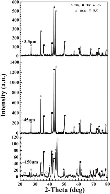
Figure 2 shows the XRD patterns of the TE products of the 40 wt% Cu–Ti–B4C system with various B4C particle sizes. The XRD result revealed that the TE products of the compacts with ∼3.5 and ∼45 μm B4C mainly consist of TiC, TiB2, and Cu without any intermediate phase, indicating that the reaction was complete. However, when the B4C particle size increased to ∼150 μm, besides TiC, TiB2, and Cu, the TiCu4 intermetallics and remnant B4C were present in the TE product, indicating that the TE reaction of the compact with ∼150 μm B4C was quit incomplete.
XRD patterns of the TE products of the 40 wt% Cu–Ti–B4C system with various B4C particle sizes.

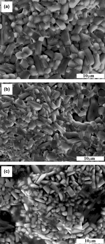
From the SEM images shown in Figs. 3(a)–3(c), it can be found that the TiC ceramic particulate with near-spherical shape and the TiB2 ceramic particulate with near-rectangular shape existed in the TE product. Moreover, with the increase of B4C particle size, the size of TiC and TiB2 ceramic decreased obviously. A higher combustion temperature and a longer dwell time at high temperature significantly promoted the crystal growth of TiC and TiB2. Cu promoted the reaction progress of Cu–Ti–B4C compact and reduced reaction difficulty. Moreover, Cu was a kind of alloying element, which was used to improve the diffusion activation of carbon in Mn-steel. Because of the same Cu content, the dwell time at high temperature was relatively same. The decrease of combustion temperature (see Fig. 1) enhanced the difficulty of crystal growth of TiC and TiB2. Therefore, with the increase of B4C particle size, the size of TiC and TiB2 turned to be smaller. Moreover, the decreasing combustion temperature reduced the pervasion of B4C particulate, resulting in the existence of B4C particulate in the TE reaction product from the ∼150 μm compact (see Fig. 2). TiC and TiB2 ceramic particulates can be fabricated from the Cu–Ti–B4C system via TE reaction, as shown in Figs. 2 and 3. To study the possibility for the production of TiC–TiB2 ceramic reinforced Mn-steel matrix composite, TE-casting experiment was conducted.
SEM micrographs of the TE products of the 40 wt% Cu–Ti–B4C system with various B4C particle sizes (a) ∼3.5 μm, (b) ∼45 μm, and (c) ∼150 μm.

B. Microstructure and phase identification of Mn-steel matrix composite
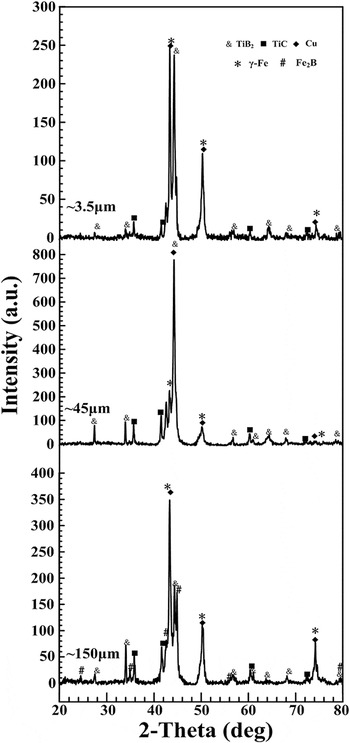
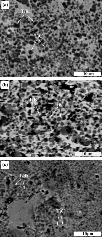
The XRD patterns of the TiC–TiB2 reinforced region of the Mn-steel matrix composites are shown in Fig. 4. From Fig. 4, it can be clearly observed that the main component of the reinforced region was TiB2, TiC, γ-Fe, and Cu, indicating that TE reaction of the composite with ∼3.5 and ∼45 μm B4C was quit complete. Fe2B existed in the Mn-steel matrix composite, indicating that TE reaction of the composite with ∼150 μm B4C particle size was incomplete. From Figs. 5(a)–5(c), the TiC ceramic particulates with near-spherical shape and the TiB2 ceramic particulates with near-rectangular shape existed in the reinforcing region. With the increase of B4C particle size, the size of TiC–TiB2 decreased clearly, which is similar to the change trend in Figs. 3(a)–3(c). However, as shown in Figs. 4 and 5, TiC–TiB2 ceramic particulates are present in the Mn-steel matrix composite, indicating that the TiC–TiB2 ceramic particulate reinforced Mn-steel matrix composites were produced via a TE-casting route successfully.
XRD patterns in the TiC–TiB2 reinforced region of the locally reinforced Mn-steel matrix composites with various B4C particle sizes.

SEM micrographs in the TiC–TiB2 reinforced regions of the locally reinforced Mn-steel matrix composites with various B4C particle sizes (a) ∼3.5 μm, (b) ∼45 μm, and (c) ∼150 μm.

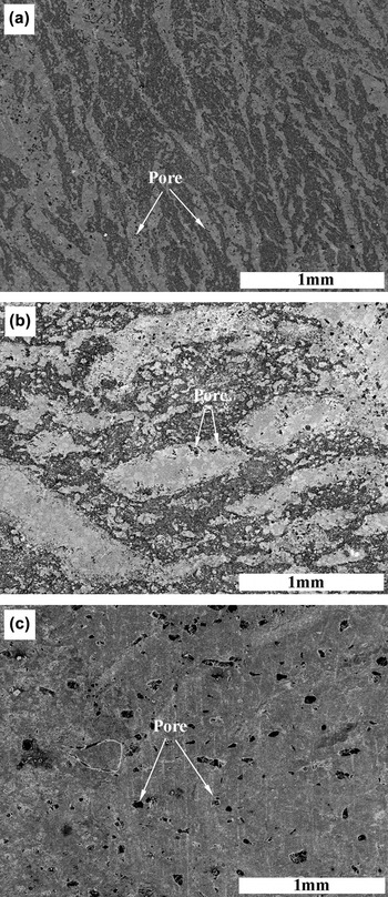
The distribution of pores in the TiC–TiB2 reinforced region of the Mn-steel matrix composites can be clearly observed in Figs. 6(a)–6(c). From Fig. 6, it can be clearly found that with the increase of B4C particle size, the number of pores increased, and the composites with ∼3.5 μm B4C presented the smallest amount of pores. Moreover, when the B4C particle size increased to ∼150 μm, it is obvious to observe that a large number of pores existed in the reinforced region. This phenomenon can be explained as follows. The shorter ignition time and higher combustion temperature resulted in the dense locally reinforced region. With the increase of B4C particle size, the ignition time increased monotonously, and the combustion temperature decreased monotonously, as shown in Fig. 1. A large number of pores were produced by the violent TE reaction. The shorter ignition time and higher combustion temperature provided sufficient time for the molten steel to infiltrate into the pores of the compact, and gas evaporated from the melt. Therefore, near-fully dense locally reinforced composite can be successfully fabricated in the Cu–Ti–B4C system with relatively small B4C particle size, as shown in Fig. 6(a).
The distribution of pores in the TiC–TiB2 reinforced regions of the locally reinforced Mn-steel matrix composites with various B4C particle sizes (a) ∼3.5 μm, (b) ∼45 μm, and (c) ∼150 μm.

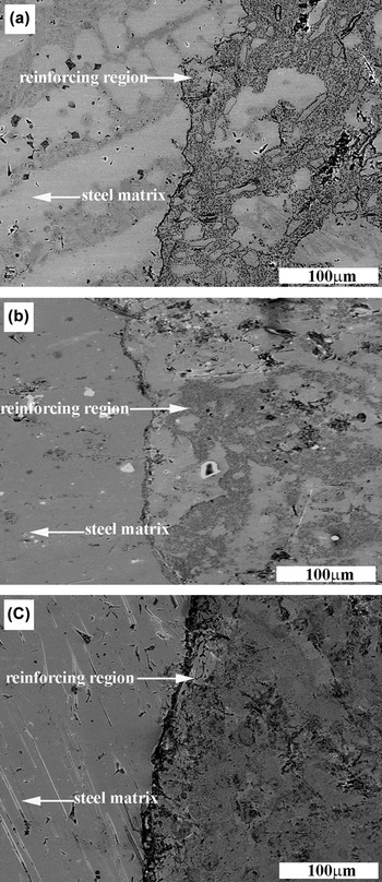
Interface micrographs between Mn-steel matrix and reinforcing region of the composite with various B4C particle sizes are shown in Figs. 7(a)–7(c). With the increase of B4C particle size, it can be clearly found that the metallurgy-bonding between the reinforcing region and matrix became poor. An obvious crack can be observed in the composite with ∼150 μm B4C particle size. The existence of the crack and the change trend can be attributed to the kinetics of TE reaction. The solidification time of the molten steel is about 62.7 sReference Tondu, Schnick, Pawlowski, Wielage, Steinhauser and Sabatier17 However, the ignition time of the composite (see Fig. 1) with various B4C particle sizes was estimated to be 480, 630, and 830 s, respectively, which were longer than solidification time. Moreover, a high combustion temperature supplied a sufficient time for the steel melt to infiltrate into the reacting compact, resulting in the strong bonding. With the increase of B4C particle size, the combustion temperature decreased monotonously. When TE reaction occurred in the compact, the solidification of molten steel had begun, which resulted in the formation of poor interface bonding. The reaction behavior and formation of TiC–TiB2 ceramic particulate reinforced Mn-steel matrix composite have been studied. To investigate the wear resistance property and wear mechanism of the composite, dry-sliding wear tests were conducted.
Interface micrographs between Mn-steel matrix and reinforcing regions of the locally reinforced Mn-steel matrix composites with various B4C particle sizes (a) ∼3.5 μm, (b) ∼45 μm, and (c) ∼150 μm.

C. Wear behavior
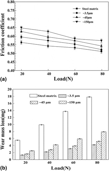
Figure 8(a) shows the variation of friction coefficient with applied load for the Mn-steel matrix and its composites with various B4C particle sizes. From Fig. 8(a), it can be found that the friction coefficient of the Mn-steel matrix composites is higher than that of the matrix, and the friction coefficients of all composites are in the range of 0.53–0.65. With the increase of B4C particle size, a measurable increase can be observed in the friction coefficient of the Mn-steel matrix composite. Figure 8(b) shows the wear mass loss of all composites varying with applied load. From Fig. 8(b), it can be seen that the wear mass loss of Mn-steel matrix composite with various B4C particle sizes is lower than that of the matrix, indicating the high wear resistance of Mn-steel matrix composite. Moreover, the composite with ∼3.5 μm B4C shows the best antiwear property. With the increase of B4C, the wear mass loss increases monotonously, which means that the size of B4C significantly affects the wear resistance of the composite.
(a) Friction coefficient and (b) wear mass loss of the Mn-steel matrix and its composites with various B4C particle sizes under different applied loads.

Hardness played a key role in enhancing the wear resistance of the materials. The appearance of TiC and TiB2 significantly strengthened the hardness of the Mn-steel matrix composite, as shown in Table I, resulting in the low wear mass loss of the composite [see Fig. 8(b)]. With the increase of B4C particle size, the wear mass loss of the composite increased monotonously, which can be attributed to the combination of hardness, size of ceramic particle, distribution of pores, and metallurgy-bonding between the reinforcing region and matrix. With the increase of B4C particle size, the size of TiC and TiB2 ceramic particulates in the local reinforcing region decreased (see Fig. 5), the interface bonding between reinforcing region and matrix became poor (see Fig. 6), and the number of pores in the local reinforcing region increased obviously (see Fig. 7). TiC and TiB2 played a load-bearing role in the dry sliding process. During the wear test, the existence of pore and crack decreased the strength of composite, which resulted in the wear mass loss of the composite with ∼45 and ∼150 μm B4C particles higher than that of the ∼3.5 μm one. After the wear test conducted for a moment, the steel around the ceramic particulate worn out firstly and resulted in ceramic particulate protruding on the wear surface, which led to the decrease of the real contact area and the adhesion between the counterparts. Moreover, the desquamated ceramic particulate and wear debris increased friction force, leading to the increase of friction coefficient of composites. The strong bonding, big size of ceramic particulate and the small number of pores resulted in the less amount of desquamated ceramic, which led to the friction coefficient of the composite with ∼3.5 μm the lowest among the Mn-steel matrix composites.
D. Wear surface
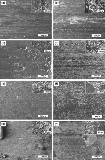
Figures 9(a)–9(h) show the SEM micrographs of the worn surfaces of the Mn-steel matrix and the TiC–TiB2 reinforced composites tested at a low applied load of 20 N and high applied load of 80 N. Compared with the Mn-steel matrix [see Figs. 9(a) and 9(b)], the Mn-steel matrix composites exhibited the lighter scratch severity. At the low load of 20 N, the worn surfaces of the composites were characterized by many long continuous grooves and a lot of wear debris, indicating that the dominant wear mechanisms were microcutting and abrasive wear, as shown in Figs. 9(c), 9(e), and 9(g). With the increase of applied load to 80 N, besides the grooves and granular wear debris, numerous delamination layers adhered on the worn surfaces, as shown in Figs. 9(d), 9(f), and 9(h). At the high load of 80 N, severe wear appeared on the worn surface of Mn-steel matrix composite, and the dominant wear mechanisms were micro-cutting and adhesive wear. To disclose the wear mechanism of the Mn-steel matrix composite further, high magnified SEM micrographs of the worn surface are shown in the top right corner of every corresponding SEM micrographs. A large amount of granular wear debris can be clearly found on the worn surfaces under the applied loads of 20 and 80 N. However, besides the granular wear debris, magnified SEM micrographs in Figs. 9(d), 9(f), and 9(h) showed the typical pattern of delamination layer clearly, indicating that the wear mechanisms of the Mn-steel matrix were microcutting and abrasive wear. From Fig. 9, it can be found that with the increase of B4C particle size, the characteristics of the worn surfaces of the Mn-steel matrix composites were relatively similar to each other. Namely, the wear mechanisms of the composite were independent of B4C particle size.
SEM micrographs of the worn surfaces of (a) Mn-steel matrix at 20 N. (b) Mn-steel matrix at 80 N. (c) Mn-steel matrix composite with ∼3.5 μm B4C at 20 N. (d) Mn-steel matrix composite with ∼3.5 μm B4C at 80 N. (e) Mn-steel matrix composite with ∼45 μm B4C at 20 N. (f) Mn-steel matrix composite with ∼45 μm B4C at 80 N. (g) Mn-steel matrix composite with ∼150 μm B4C at 20 N. (h) Mn-steel matrix composite with ∼150 μm B4C at 80 N.

The presence of the hard reinforcement changed the contact characteristics between pin and disc. During the wear process, because of the disparity of the hardness between reinforced region and matrix, the matrix of the composite was worn out firstly. The movement of a mating disc removed or pushed the wear debris into ridges along the sides of the sliding direction, forming the grooves on the worn surface. The removal of matrix exposed the TiC and TiB2 ceramic, which enhanced the load bearing role of ceramic particulate and increased the desquamation possibility of ceramic. The desquamated ceramic particulate and Mn-steel matrix changed the wear behaviors, as shown in Fig. 8, forming the abrasive wear mechanism. TiC–TiB2 acted as a hard barrier role to resist the plastic deformation of composites. The shear stress occurred in the contact region resulted in the flaking off of the matrix, which generated the plastic deformation periodically. Because of the plastic deformation between pins and disc, stress concentration occurred easily, forming the delamination layer phenomenon as shown in the magnified SEM micrographs. The delamination layer protected the composite from further friction, enhancing the wear resistance of the Mn-steel matrix composite. The increase of applied load led to the dominant wear mechanism of composite changing from abrasive wear to adhesion wear. Considering the economy, efficiency, high density, and perfect wear resistance, TiC–TiB2 ceramic particulate locally reinforced Mn-steel matrix composite fabricated from a Cu–Ti–B4C system via a TE-casting route can be widely used in practical applications.
IV. CONCLUSIONS
In this study, the reaction behavior and wear mechanism of TiC–TiB2 ceramic particulate locally reinforced Mn-steel matrix composites from a Cu–Ti–B4C system with various B4C particle sizes via a TE-casting route were studied. Moreover, the TE reaction behaviors of the Cu–Ti–B4C compact with various B4C particle sizes were also studied and drew the following conclusions:
(1) TiC–TiB2 ceramic particulates can be fabricated successfully from a Cu–Ti–B4C system through TE reaction. With the increase of B4C particle size from ∼3.5 to ∼150 μm, the ignition temperature increased from 877 to 926 °C, and combustion temperature decreased from 2308 to 1827 °C, respectively. Moreover, with the increase of B4C particle sizes, the size of the TiC and TiB2 ceramic particulates became smaller.
(2) The Mn-steel matrix composites locally reinforced with in situ TiC–TiB2 ceramic particulates were successfully fabricated using the TE-casting route in a Cu–Ti–B4C system with various B4C particle sizes. The hardness, friction coefficient, and wear resistance of the Mn-steel matrix composite were higher than those of the Mn-steel matrix. The composite with ∼3.5 μm B4C exhibited the best wear resistance and the lowest friction coefficient among all the Mn-steel matrix composites. With the increase of B4C particle size, the size of the TiC and TiB2 ceramic particulates in the local reinforcing regions decreased, the interface bonding between reinforcing region and matrix became poor, and the number of pores in the local reinforcing regions increased.
(3) The dominant wear mechanisms of the Mn-steel matrix composites were microcutting and abrasive wear at a low applied load of 20 N. With the increase of applied load to 80 N, the dominant wear mechanisms of the Mn-steel matrix composite were microcutting and adhesion wear associated with the formation of delamination layer. The existence of delamination layer significantly protected the composite from further wear, enhancing the wear resistance of the composite under the condition of high load of 80 N.
ACKNOWLEDGMENTS
This work is supported by Cooperative Innovation Platform of National Oil Shale Exploration Development and Research, the National Natural Science Fundation (No. 51205160 and 51375006), the Science and Technology Development Project of Jilin Province (No. 201201025 and 20140520121JH), and the Specialized Research Fund for the Doctoral Program of Higher Education of China (No. 20120061120110).