1. Introduction
The robotics industry has developed rapidly with the advent of “Industry 4.0.” The human–robot relationship is evolving from robotic replacement of human roles to human–robot collaboration, with “human–robot collaboration” now seen as a primary direction for robotic applications. Reference [Reference Villa, Mobedi and Arash1] fully utilized the potential of human-robot collaboration by successfully accomplishing the task of screwing through human-robot collaboration. Human–robot integration and collaboration demonstrate the core value of intelligent robots [Reference Chen2], combining human strengths in cognition and problem-solving with robotic advantages in efficiency, durability, and accuracy [Reference Wang and Zhao3].
Zero-force drag technology enables robots to meet human work requirements better, facilitating seamless human–robot integration. In zero-force drag mode, minimal force is required to guide the robot in response to external forces, making zero-force drag a key research area in human–robot collaboration. Zero-force drag can be achieved primarily through torque-based [Reference Wei4–Reference Lei, Huang, Zhong and He7] and position-based [Reference Reyes-Uquillas and Hsiao8–Reference Xu, Zhi and Dong13] methods. In position-based zero-force drag, the robot translates the magnitude and direction of external forces into displacement values, which are input to the robot controller, setting joint motor drivers to position mode. This approach often requires installing joint torque or six-axis force sensors on the robot to detect external forces; however, such sensors are costly and increase maintenance needs. Conversely, torque-based zero-force drag requires no additional force sensors. It achieves compliant motion by converting position deviations into joint driving torques, enabling joint motor drivers to operate in torque mode. This method is widely applicable, as it only requires torque mode support from the driver. However, torque mode demands a precise robot dynamics model and can result in higher starting torque, possibly reducing system compliance.
An accurate robot dynamic model is essential for precise control, dynamic design, and motion simulation [Reference Huynh, Assadi, Rivière-Lorphèvre, Verlinden and Ahmadi14, Reference Ding, Chen, Wu and Shen15]. At low constant speeds, collaborative robots use approximately
 $ 25\mathrm{\%}$
of their driving torque to offset joint friction, with gravity and friction comprising the primary components of driving torque in small- to medium-sized robots [Reference Yu, Li, Yang and Liu16–Reference Li, Li, Ding, Li and Yang18]. A high-accuracy dynamic model significantly improves control precision and operational performance [Reference Tu19, Reference Qian, Li, Du, Li, Ding, Li and Li20]. Direct measurement of dynamic parameters is challenging due to robot complexity and assembly errors. CAD measurement is commonly used but is inaccurate and unsuitable for high-precision control. Experiment-based parameter identification is the only viable method for accurately obtaining dynamics [Reference Qin, Baron and Birglen21, Reference Liu, Yao and Ke22]. In ref. [Reference Li23], a simplified robot model is used for gravity and friction identification, though this convenient approach suffers from low gravity parameter accuracy. Reference [Reference Zou and Ding24] employs particle swarm optimization to enhance the precision of dynamic parameters by optimizing the excitation trajectory, though it depends on costly joint torque sensors.
In robot dragging, the maximum static friction within the joints makes initiating motion from rest more challenging and strenuous [Reference Deng, Liu, Min and Wang25–Reference Iwatani and Kikuuwe27]. When the applied force is insufficient, the joint becomes challenging to drag; however, excessive force may lead to an overshoot. Furthermore, the rapid increase in speed during dragging can heighten the impact and wear on components, reduce control accuracy during dragging, and potentially cause system instability, compromising dynamic responsiveness. This issue is particularly problematic in high-precision applications, where it can render the system incapable of performing adequately. Current methods for start-up torque compensation are mainly based on the Coulomb-viscous friction model, applying an alternating square-wave preload to the motors of stationary joints [Reference Xiao28–Reference Iwatani and Kikuuwe30]. Although this approach somewhat reduces starting torque, it has notable limitations. Applying square waves may lead to sudden torque changes, adversely affecting joint movement. Additionally, the correlation between compensation frequency and starting torque has not been explored, and there is a lack of comprehensive experimental validation and detailed support.
This paper proposes a current feedback-based method for identifying robot dynamic parameters to identify robot gravity and friction precisely. This method does not rely on joint force sensors, gear ratios, or torque coefficients; it only requires joint current feedback from the robot. While reducing the complexity of parameter identification, this method achieves high identification accuracy, verified through experiments. A torque-based zero-force drag algorithm is designed based on the identification results for gravity and friction. This algorithm primarily comprises gravity and friction compensation, featuring a simple structure that is easy to implement and suitable for practical applications. A starting torque compensation algorithm based on the Stribeck friction model is proposed to address the issue of high starting torque in zero-force drag. By designing a maximum static friction sinusoidal compensation, the algorithm effectively reduces the starting torque for each joint. Relevant experiments were conducted to establish the relationship between compensation frequency and starting torque, verifying the method’s effectiveness.
2. Identification of gravity and friction models
2.1. Extraction of gravity term torque
For a serial robot with
 $ n$
degrees of freedom, its dynamic model can be represented as
 \begin{align} \boldsymbol{M}(\boldsymbol{q})\ddot{\boldsymbol{q}}+\boldsymbol{C}(\boldsymbol{q},\dot{\boldsymbol{q}})\dot{\boldsymbol{q}}+\boldsymbol{G}(\boldsymbol{q}) = \boldsymbol{\tau}\end{align}
where
 $ \boldsymbol{M}(\boldsymbol{q})\in \boldsymbol{R}^{n\times n}$
denote the positive-definite inertia matrix of the robot,
 $ \boldsymbol{C}(\dot{\boldsymbol{q}},\boldsymbol{q})\in {\boldsymbol{R}}^{n\times n}$
is the centrifugal and Coriolis forces matrix of the robot,
 $ \boldsymbol{G}(\boldsymbol{q})\in {\boldsymbol{R}}^{n\times n}$
is the gravity vector of the robot, which depends only on the position of the robot,
 $ \boldsymbol{\tau}\in {\boldsymbol{R}}^{n\times 1}$
is the joint driving torque, which is a column vector composed of
 $ n$
joint torques, denoted as
 $ \boldsymbol{\tau}={\left[{\tau }_{1},{\tau }_{2},\cdots, {\tau }_{3}\right]}^{T},\mathrm{and}\ \boldsymbol{q}\in {\boldsymbol{R}}^{n\times 1}$
is the column vector of joint angles
 $ {\theta }_{i}$
, represented as
 $ \boldsymbol{q}={\left[{\theta }_{1},{\theta }_{2},\cdots, {\theta }_{n}\right]}^{T}$
. Similarly,
 $ \dot{\boldsymbol{q}},\ddot{\boldsymbol{q}}\in {\boldsymbol{R}}^{n\times 1}$
the column vectors of joint angular velocities
 $ {\dot{\theta }}_{i}$
and angular accelerations
 $ {\ddot{\theta }}_{i}$
.
According to the Lagrange’s equation, the
 $ i$
th term in the dynamic model is
 \begin{align} {g}_{i} (\boldsymbol{q})=\frac{\partial U}{\partial {q}_{i}}=-\sum _{j=i}^{n} \left({m}_{j} \mathop g\limits^{-}{}^{T}\frac{\partial_{j}^{0}\boldsymbol{T}}{\partial {q}_{i}}\cdot {}^j{\tilde{\boldsymbol{r}}}_{cj}\right) \end{align}
where
 $ U$
is the potential energy of the robot,
 $ {q}_{i}$
is the angle of joint
 $ i,{m}_{j}$
is the mass of joint
 $ j, \mathop g\limits^{-}$
is the local gravitational acceleration,
 $ {}_{j}^{0}\boldsymbol{T}$
is the homogeneous transformation matrix of joint
 $ j, {}^{j}{\tilde{\boldsymbol{r}}}_{cj}$
is the position vector of the center of mass of link
 $ j$
.
In the case of a serial robot, it is simple to obtain the current joint angle
 $ {}^{q}$
using encoders. As a result, in Eq. (2), there are still four parameters left to be determined to calculate each joint’s gravity term: the link mass
 $ {m}_{i}$
and the position vector of the link’s center of mass
 $ {}^{j}{\tilde{\boldsymbol{r}}}_{cj}={\left[{x}_{ci},{y}_{ci},{z}_{ci}\right]}^{T}$
. These two parameters can be extracted and linearly combined as follows:
 \begin{align} \boldsymbol{p}_{gi}={\left[{m}_{i},{m}_{i}{x}_{ci},{m}_{i}{y}_{ci},{m}_{i}{z}_{ci}\right]}^{T} \end{align}
Let
 $ {\boldsymbol{p}}_{gi}$
be the gravity parameter set for link
 $ i$
. Combining Eq. (3) with Eq. (2) and converting it into a linear regression model with respect to
 $ {\boldsymbol{p}}_{gi}$
:
 \begin{align} \boldsymbol{G}(\boldsymbol{q})=\boldsymbol{Y}_{g}(\boldsymbol{q})\boldsymbol{P}_{g}\end{align}
where
 $ {\boldsymbol{Y}}_{g}(\boldsymbol{q})\in {\boldsymbol{R}}^{n\times 4n},(\boldsymbol{P})_{g}\in {\boldsymbol{R}}^{4n\times 1}$
.
Introducing joint friction and transforming Eq. (1) into the following form:
 \begin{align} \boldsymbol{M}(\boldsymbol{q})\ddot{\boldsymbol{q}} + \boldsymbol{C}(\boldsymbol{q},\dot{\boldsymbol{q}})\dot{\boldsymbol{q}} + \boldsymbol{G}(\boldsymbol{q})+\boldsymbol{\tau}_{f}=\boldsymbol{\tau}_{m} \end{align}
where
 $ {\boldsymbol{\tau}}_{f}\in {\boldsymbol{R}}^{n\times 1}$
is the combined friction torque introduced at the motor end and the reducer end. This paper assumes that the friction force
 $ {\tau }_{f}$
at each joint is an odd function of velocity, that is,
 $ {\tau }_{fi}\left({\dot{\theta }}_{i}\right)=-{\tau }_{fi}({-}{\dot{\theta }}_{i})\cdot {\tau }_{m}$
is the driving torque of the joint motor after being amplified by the reducer.
The linear relationship between the output torque of the motor, amplified by the reducer, and the motor armature current is as follows:
 \begin{align} {\tau }_{mi}={n}_{i}{k}_{i}{I}_{i} \end{align}
where
 $ {n}_{i}$
is the reduction ratio of the joint reducer;
 $ {k}_{i}$
is the torque constant;
 $ {I}_{i}$
is the motor armature current.
When the robot is in the following state:
 \begin{align} \begin{cases} \boldsymbol{q}({t}_{1}) = \boldsymbol{q}({t}_{2}) = \boldsymbol{\varphi}\\[3pt] \dot{\boldsymbol{q}}({t}_{1}) = -\dot{\boldsymbol{q}}({t}_{2}) = \dot{\boldsymbol{\varphi}},\\[3pt]\ddot{\boldsymbol{q}}({t}_{1}) = -\ddot{\boldsymbol{q}}({t}_{2}) = 0 \end{cases} \quad||\dot{\boldsymbol{\varphi}} ||_{2} \lt \varepsilon \end{align}
where
 $ \Vert \dot{\varphi }{\Vert }_{2}$
represents the 2-norm of
 $ \dot{\varphi }$
, and
 $ \varepsilon $
is a very small positive value. Equation (7) indicates that when the joint is in the same position, moving at a constant low speed but in opposite directions, its inertial force
 $ \boldsymbol{M}(\boldsymbol{q})\ddot{\boldsymbol{q}}=0$
, centrifugal and Coriolis forces
 $ \boldsymbol{C}(\boldsymbol{q},\dot{\boldsymbol{q}})\dot{\boldsymbol{q}}\approx 0$
, and the gravitational torque remains the same. Substituting Eq. (7) into Eq. (5) yields:
 \begin{align} \begin{cases} \boldsymbol{\tau}_{m}(t_{1}) = \boldsymbol{G}(\boldsymbol{q}) + \boldsymbol{\tau}_{f}(t_{1}) \\[3pt]\boldsymbol{\tau}_{m}(t_{2}) = \boldsymbol{G}(\boldsymbol{q}) + \boldsymbol{\tau}_{f}(t_{2}) \end{cases} \mathop \Rightarrow\limits^{Add} \boldsymbol{G}(\boldsymbol{q}) = [\boldsymbol{\tau}_{m}(t_{1}) + \boldsymbol{\tau}_{m}(t_{2})]/2 \end{align}
From Eq. (8), the gravitational torque can be calculated based on the motor driving torque. This paper does not require obtaining the specific values of the reducer reduction ratio
 $ {n}_{i}$
and the motor torque constant
 $ {k}_{i}$
in advance.
Combining Eqs. (4) and (6), the joint torque can be converted into the form of motor armature current:
 \begin{align} & \boldsymbol{Y}_{gi} (\boldsymbol{q})\boldsymbol{P}_{gi} = {\tau _{gi}} = {n_i}{k_i}{I_i} \nonumber\\[3pt]& \Rightarrow \boldsymbol{Y}_{gi} (\boldsymbol{q})\frac{\boldsymbol{P}_{gi}} {{{n_i}{k_i}}} = {I_{gi}} \nonumber\\[3pt] & \Rightarrow \boldsymbol{Y}_{gi} (\boldsymbol{q})P_{gi}^{\prime} = I_{gi} \end{align}
2.2. Extraction of identifiable gravity parameters
According to Eq. (4), the gravitational torque term
 $ \boldsymbol{G}(\boldsymbol{q})$
can be derived from the observation matrix
 $ \boldsymbol{Y}_{g}(\boldsymbol{q})$
and the link gravity parameters
 $ \boldsymbol{P}_{\boldsymbol{g}}$
. The observation matrix
 $ \boldsymbol{Y}_{g}(\boldsymbol{q})$
is formed by the joint angles
 $ \boldsymbol{q}$
in the excitation trajectory. However, because some gravity parameters in
 $ \boldsymbol{P}_{g}$
are linearly correlated, the observation matrix
 $ \boldsymbol{Y}_{g}(\boldsymbol{q})$
is not total rank, which prevents the solution of Eq. (4). Hence, it is essential to perform linear independence processing on
 $ \boldsymbol{P}_{g}$
. This paper employs extracting the minimal gravity parameter set from the MDH parameter set in ref. [Reference Liu, Li, Fang, Han and Zhang17].
For an n-degree-of-freedom serial robot, the complete inertia parameter set for joint
 $ i$
is
 \begin{align} \boldsymbol{P}_{i}=\left[{m}_{i},{m}_{i}{r}_{cxi},{m}_{i}{r}_{cyi},{m}_{i}{r}_{czi},{I}_{ixx},{I}_{ixy},{I}_{xz},{I}_{iyy},{I}_{iyz},{I}_{izz}\right] \end{align}
where
 $ {m}_{i}$
represents the mass of joint
 $ i,{r}_{cxi},{r}_{cyi},{r}_{czi}$
the center of mass position vector of the joint
 $ i,{I}_{ixx}$
the inertia tensor parameters for joint
 $ i$
, the same applies to others. The total number of inertia parameters for a 6-degree-of-freedom UR configuration robotic arm is 60. After obtaining
 $ \boldsymbol{P}_{i}$
, Eq. (1) can be reorganized into a linear regression equation.
 \begin{align} \boldsymbol{\tau} =\boldsymbol{Y}(\boldsymbol{q},\dot{\boldsymbol{q}},\ddot{\boldsymbol{q}})\boldsymbol{P}\end{align}
where
 $ \boldsymbol{P}={\left[\boldsymbol{P}_{1},\boldsymbol{P}_{2},\cdots, \boldsymbol{P}_{n}\right]}^{T}$
. Due to the presence of linearly dependent inertia parameters in
 $ (\boldsymbol{P})$
,
 $ \boldsymbol{Y}(\boldsymbol{q},\dot{\boldsymbol{q}},\ddot{\boldsymbol{q}})$
suffers from rank deficiency, making it impossible to solve. Thus, it is required to extract linearly independent items from
 $ (\boldsymbol{P})$
to create a minimal inertia parameter set.
Segment the robotic arm joint i into three conditions: R1, R2, and R3:
-
• R1: Rotational joints exist among joints 0 to
 $ i-1$
whose axes are not parallel to the axis of joint
$ i$
.
-
• R2: There are no rotational joints among joints 0 to
$ i-1$
whose axes are not parallel to the axis of joint
$ i$
, but there exist rotational joints whose axes do not coincide with the axis of joint
$ i$
. -
• R3: There are no rotational joints among joints 0 to
$ i-1$
whose axes do not coincide with the axis of joint
$ i$
.


In a UR configuration pure rotational robotic arm, axis 1 is classified as R3, and the other joints are classified as R1.
Once the joint types are determined, the minimal inertia parameter set can be calculated in the sequence from
 $ n$
to 1 using the following approach:
-
1. For joint
$ n$
, the initial value is configured as

 \begin{align} & \left\{ XX_{n},XY_{n},XZ_{n},YY_{n},YZ_{n},ZZ_{n},MX_{n},MY_{n},MZ_{n},M_{n} \right\}\nonumber\\[3pt]& = \left\{ xx_{n},xy_{n},xz_{n},yy_{n},yz_{n},zz_{n},mx_{n},my_{n},mz_{n},m_{n} \right\} \end{align}
-
2. If joint
$ i$
is classified as R1, the minimal inertia parameter for joint
$ i$
is
$ X{X}_{i}^{\star }=X{X}_{i}-Y{Y}_{i},X{Y}_{i},X{Z}_{i},Y{Z}_{i},Z{Z}_{i},M{X}_{i},M{Y}_{i}$
, and the inertia parameters for joint
$ i-1$
after reorganization are


 \begin{align*} XX_{i - 1} & = xx_{i - 1} + YY_{i} + 2d_{i}MZ_{i} + d^{2}_{i}M_{i} \nonumber\\[3pt]XY_{i - 1} {} &= xy_{i - 1} + as\alpha_{i}(MZ_{i} + d_{i}M_{i} )\nonumber\\[3pt]XZ_{i - 1} &= xz_{i - 1} + a_{i}c\alpha_{i}(MZ_{i} + d_{i}M_{i} )\nonumber\\[3pt]YY_{i - 1} & = yy_{i - 1} + c^{2}a_{i}YY_{i} + 2d_{i}c^{2}\alpha_{i}MZ_{i} + (d^{2}_{i}c^{2}\alpha_{i} + a^{2}_{i})M_{i}\nonumber\\[3pt]YZ_{i - 1} &= yz_{i - 1} + cs\alpha_{i}(YY_{i} + 2d_{i}MZ_{i} + d^{2}_{i}M_{i} \nonumber\\[3pt]\end{align*}
 \begin{align} ZZ_{i - 1} & = zz_{i - 1}+ s^{2}\alpha_{i}YY_{i} + 2d_{i}s^{2}\alpha_{i}MZ_{i} + (d^{2}_{i}s^{2}\alpha_{i} + a^{2}_{i})M_{i}\nonumber\\[3pt]MX_{i - 1} &= mx_{i - 1} + a_{i}M \nonumber\\[3pt]MY_{i - 1} &= my_{i - 1} - s\alpha_{i}(MZ_{i} + d_{i}M_{i})\nonumber\\[3pt]MZ_{i - 1} &= mz_{i - 1} - c\alpha_{i}(MZ_{i} + Vd_{i}M_{i}) \nonumber\\[3pt]M_{i - 1} &= m_{i - 1} + {M_i}\end{align}
-
3. If joint
$i$
is classified as R3, the minimal inertia parameter for joint
$i$
is
$Z{Z_i}$
, and the inertia parameters for joint
$i - 1$
after reorganization are


 \begin{align} XX_{i - 1} & = xx_{i - 1}\nonumber\\[3pt]XY_{i - 1} {} &= xy_{i - 1}\nonumber\\[3pt]XZ_{i - 1} &= xz_{i - 1}\nonumber\\[3pt]YY_{i - 1} & = yy_{i - 1}\nonumber\\[3pt]YZ_{i - 1} &= yz_{i - 1}\nonumber\\[3pt]ZZ_{i - 1} &= zz_{i - 1}\\[3pt]MX_{i - 1} &= mx_{i - 1}\nonumber\\[3pt]MY_{i - 1} &= my_{i - 1}\nonumber\\[3pt]MZ_{i - 1} &= mz_{i - 1}\nonumber\\[3pt]M_{i - 1} &= m_{i - 1} + {M_i} \nonumber \end{align}
From the above conditions, it can be concluded that the number of parameters in the minimal inertia parameter set for a UR configuration robotic arm is
 \begin{align} {n_{{\rm{min\;}}}} = 7{n_{R1}} + {n_{R3}} \end{align}
In the case of the 6-degree-of-freedom UR configuration robot presented in this paper, the minimal inertia parameter set consists of 36 parameters, indicating a reduction of 24 linearly correlated items compared to the complete inertia parameter set. Then, Eq. (11) is further simplified to:
 \begin{align} \boldsymbol{\tau} = \boldsymbol{Y}_{r}(\boldsymbol{q}, \dot{\boldsymbol{q}}, \ddot{\boldsymbol{q}})\boldsymbol{P}_{r} \end{align}
where
 $ \boldsymbol{P}_r$
represents the robot’s complete minimal inertia parameter set,
 $ \boldsymbol{Y}_r(\boldsymbol{q}, \dot{\boldsymbol{q}}, \ddot{\boldsymbol{q}})$
is the associated minimal observation matrix. In order to extract the minimal gravity parameter set
 $\boldsymbol{P}_{gr}$
, it is clear that
 ${\boldsymbol{P}_{gr}} \in {\boldsymbol{P}_r}$
. According to Eq. (4), the gravity parameter set is solely associated with the link mass
 $m$
and the link center of mass vector
 ${\tilde{\boldsymbol{r}}}_{c}$
. Thus, the corresponding observation matrix
 ${\boldsymbol{P}_{gr}}$
can be derived from
 ${\boldsymbol{P}_r}$
based on these two parameters. Subsequently, the corresponding observation matrix
 $\boldsymbol{Y}_{gr}(\boldsymbol{q}, \dot{\boldsymbol{q}}, \ddot{\boldsymbol{q}})$
can be extracted from
 $\boldsymbol{Y}_{r}(\boldsymbol{q}, \dot{\boldsymbol{q}}, \ddot{\boldsymbol{q}})$
using the same corresponding approach. Additionally, since the gravitational torque depends only on position, setting
 $ \dot{\boldsymbol{q}} = \ddot{\boldsymbol{q}} = 0$
in
 $\boldsymbol{Y}_{gr}(\boldsymbol{q}, \dot{\boldsymbol{q}}, \ddot{\boldsymbol{q}})$
leads to:
 \begin{align} \boldsymbol{G}(\boldsymbol{q}) = \boldsymbol{Y}_{gr} (\boldsymbol{q})\boldsymbol{P}_{gr} \end{align}
where
 ${\boldsymbol{Y}_{gr}}(\boldsymbol{q}) \in {\boldsymbol{R}^{n \times 2\left( {n - 1} \right)}},{\rm{\;}}{\boldsymbol{P}_{gr}} \in {R^{2\left( {n - 1} \right) \times 1}}$
. Since joint 1 is not influenced by gravity when the robot is installed vertically, so
 $\boldsymbol{G}({{\boldsymbol{q}_1}}) = 0 \Rightarrow {\boldsymbol{P}_{gr1}} = \boldsymbol{0}$
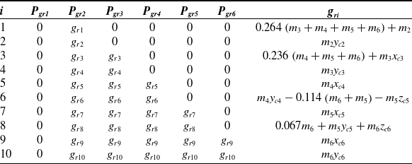
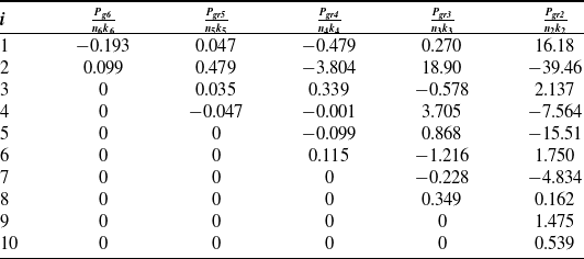
. While Eq. (17) lacks any physical meaning, gravity parameters can be identified based on both Eq. (17) and Eq. (11), And the contents of the
 ${\boldsymbol{P}_{gr}}$
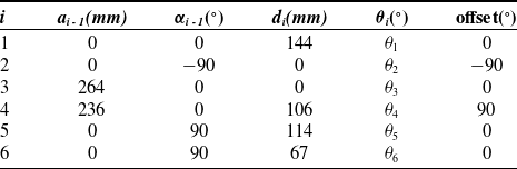
parameters obtained after linear independence processing and substituting the robot MDH parameters (the MDH parameters are shown in Table VII) are shown in Table I.
 $\boldsymbol{P}_{gr}$
parameters.

2.3. Friction torque extraction method and friction model
During the operation of a robot, friction is a crucial factor that cannot be overlooked. Standard friction models include:
-
• Coulomb-Viscous Friction Model
 \begin{align} f(v) = {f_v}v + {f_c}\,{\rm sgn}(v)\end{align}
-
• Stribeck Friction Model
 \begin{align} f(v) = {f_v}v + {f_c}\,{\rm sgn}(v) + \left( {{f_s} - {f_c}} \right){e^{ - {{(vv/vs)}^s}}}{\rm sgn}(v) \\[-14pt] \nonumber\end{align}
where
 ${f_c}$
is the Coulomb friction force,
 ${f_v}$
is the viscous friction coefficient,
 ${f_s}$
is the maximum static friction force,
 ${v_s}$
is the Stribeck velocity, and
 $\delta $
is an empirical parameter, usually set to
 $\delta = 1$
or
 $\delta = 2$
. The main differences between the two friction models are shown in Figure 1.
Two friction models.

The Stribeck friction model shows that friction increases as speed increases at medium to high speeds and describes nonlinear properties at low speeds, making it more consistent with real-world conditions. In the Coulomb-viscous friction model, the Coulomb friction force
 ${f_c}$
at rest is smaller than the actual maximum static friction force
 ${f_s}$
, which can reduce the effectiveness of subsequent start-up torque compensation techniques. Therefore, this paper chooses to use the Stribeck friction model for friction identification.
In order to determine the friction torque
 $\boldsymbol{\tau}_f$
from the motor driving torque
 $\boldsymbol{\tau}_{m}$
, joint i can be set to move at a constant speed with the same angle but in opposite directions while the other joints remain stationary.
 \begin{align} \begin{cases} \theta_{i}({t_{1}}) = \theta_{i}({t_{2}}) = \varphi\\[3pt]\dot{\theta}_{i}({t_{1}}) = \dot{\theta}_{i}({t_{2}}) = \dot{\varphi}\\[3pt]\ddot{\theta}_{i}({t_{1}}) = \ddot{\theta}_{i}({t_{2}}) = 0 \end{cases}\end{align}
where
 $\phi $
can be any value within the range of motion of joint
 $i$
, and
 $\dot \phi $
is the joint velocity with
 $\dot \phi \ne 0$
. At instant
 ${t_1}$
and
 ${t_2}$
, the acceleration is zero, so the inertial force
 $\boldsymbol{M}(\boldsymbol{q}) \ddot{\boldsymbol{q}} = 0$
; only axis
 $i$
is moving, so
 $\boldsymbol{C}(\boldsymbol{q},\dot{\boldsymbol{q}})\dot{\boldsymbol{q}} = 0$
; at this instant, the friction forces for joint
 $i$
are opposite and the gravitational forces are the same. Combining with Eq. (5):
 \begin{align} {\tau _{fi}}({\dot \varphi } ) = {f_i} = \left[ {{\tau _{mi}}({{t_1}}) - {\tau _{mi}}( {{t_2}})} \right]/2 \end{align}
At this point, the friction torque can be extracted from the motor driving torque.
3. Zero-force drag and start-up compensation
3.1. Zero-force drag
During the motion of the robot, the joint driving torque is mainly composed of two parts: compensation from the robot’s dynamic model and compensation for the friction torque:
 \begin{align} \boldsymbol{\tau}_{m} = \boldsymbol{C} (\boldsymbol{q}, \dot{\boldsymbol{q}})\dot{\boldsymbol{q}} + \boldsymbol{G} (\boldsymbol{q}) + \boldsymbol{\tau}_{f} \end{align}
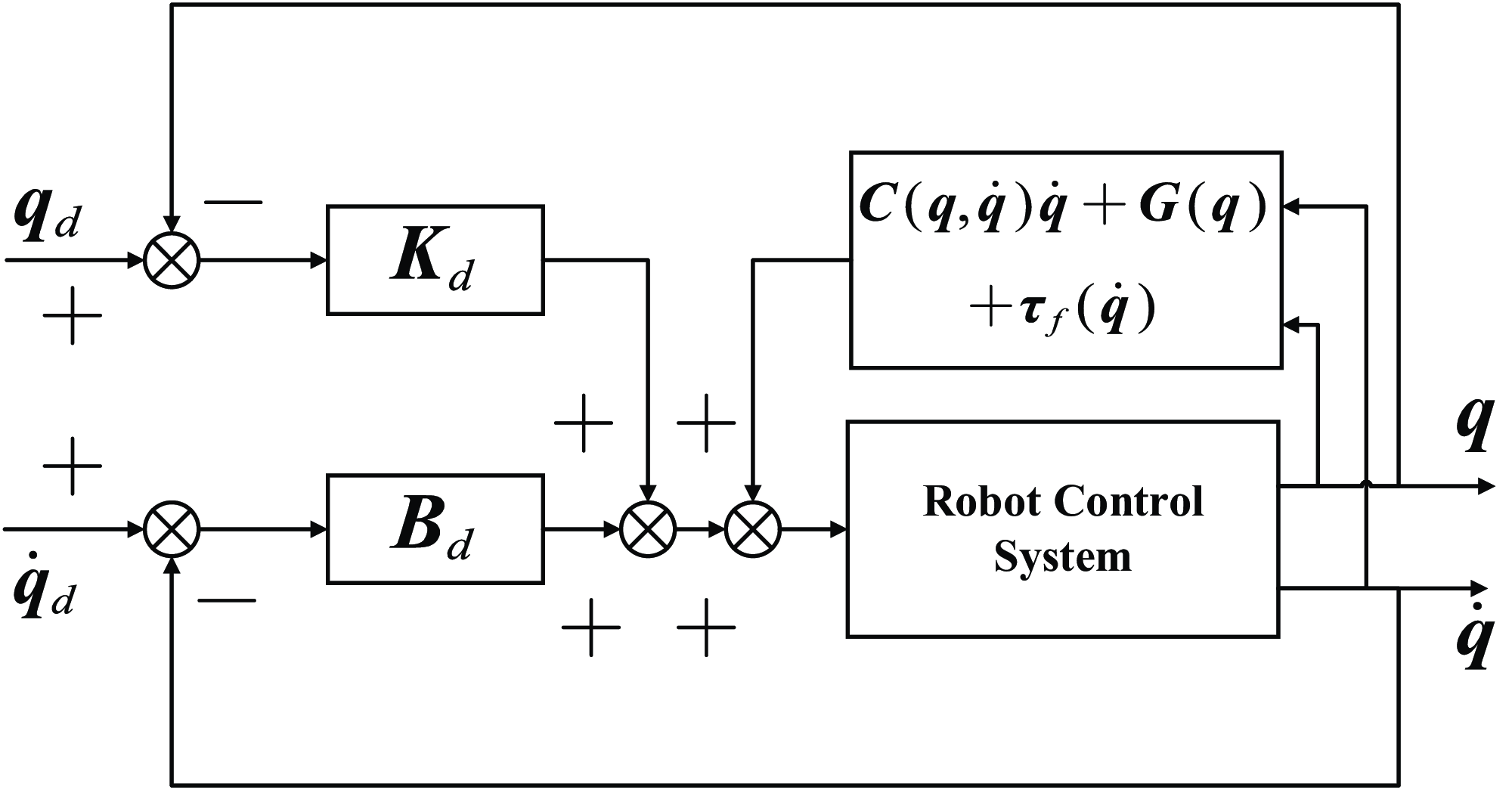
Combining Eq. (22) with PD control, the zero-force drag control law can be obtained as shown in Eq. (23). The control diagram is illustrated in Figure 2. Here,
 $ \boldsymbol{K}_{d}$
is an
 $n \times n$
diagonal matrix representing the system stiffness, and
 $\boldsymbol{B}_{d}$
is an
 $n \times n$
diagonal matrix representing the system damping. In general, setting
 $\boldsymbol{K}_{d} = 0$
allows the robot stiffness to be zero, thus enabling zero-force drag for the robot.
 \begin{align} \boldsymbol{\tau}_{m} = \boldsymbol{C} (\boldsymbol{q},\dot{\boldsymbol{q}}) \dot{\boldsymbol{q}} + \boldsymbol{G}(\boldsymbol{q}) + \boldsymbol{\tau}_{f} + \boldsymbol{K}_d \boldsymbol{q}_{e} + \boldsymbol{D}_{d} \dot{\boldsymbol{q}}_{e} \end{align}
Block diagram of torque-based zero-force drag.

In the equation,
 ${\boldsymbol{q}_e} = {\boldsymbol{q}_d} - \boldsymbol{q}$
represents the joint angle error, and
 $\dot{\boldsymbol{q}}_{e} = \dot{\boldsymbol{q}}_{d} - \dot{\boldsymbol{q}}$
represents the joint velocity error. This control law is simple in form and low in complexity.
3.2. Start-up torque compensation algorithm
The robot experiences difficulty in movement when initially dragged from a stationary position. Neither the Coulomb-viscous friction model, as described in Eq. (18), nor the Stribeck friction model, as described in Eq. (19), can compensate for the friction at rest. To initiate joint movement, overcoming the maximum static friction force is necessary, making the start-up process laborious. As the robot begins to move, the controller attempts to compensate for the friction torque of each joint based on the feedback velocity. However, abrupt changes in friction torque at zero velocity cause sudden friction compensation torque during start-up, leading to sudden acceleration of each joint and making control difficult. When attempting to move the robot within a small range, it is easy to experience overshoot.
This paper compensates for the maximum static friction force
 ${f_s}$
of the joints in a stationary state, thereby reducing the required starting torque. Specifically, the joint driving torque at rest is given by
 \begin{align} \boldsymbol{\tau} = \boldsymbol{G}( \boldsymbol{q} ) + \boldsymbol{\tau} _{fmax} \end{align}
The maximum static friction force at each joint is compensated using an alternating sinusoidal waveform, as the direction in which the robot will be dragged is unknown. It is crucial to accurately calculate the maximum static friction force
 ${f_s}$
for the joints, making applying the Stribeck friction model more suitable. The analytical expression for the friction compensation at each joint in a stationary state is as follows:
 \begin{align} \tau _{fs} = f_{s}\sin\!({wt}) \end{align}
Compared to traditional compensation methods, using sinusoidal wave compensation offers the following advantages:
-
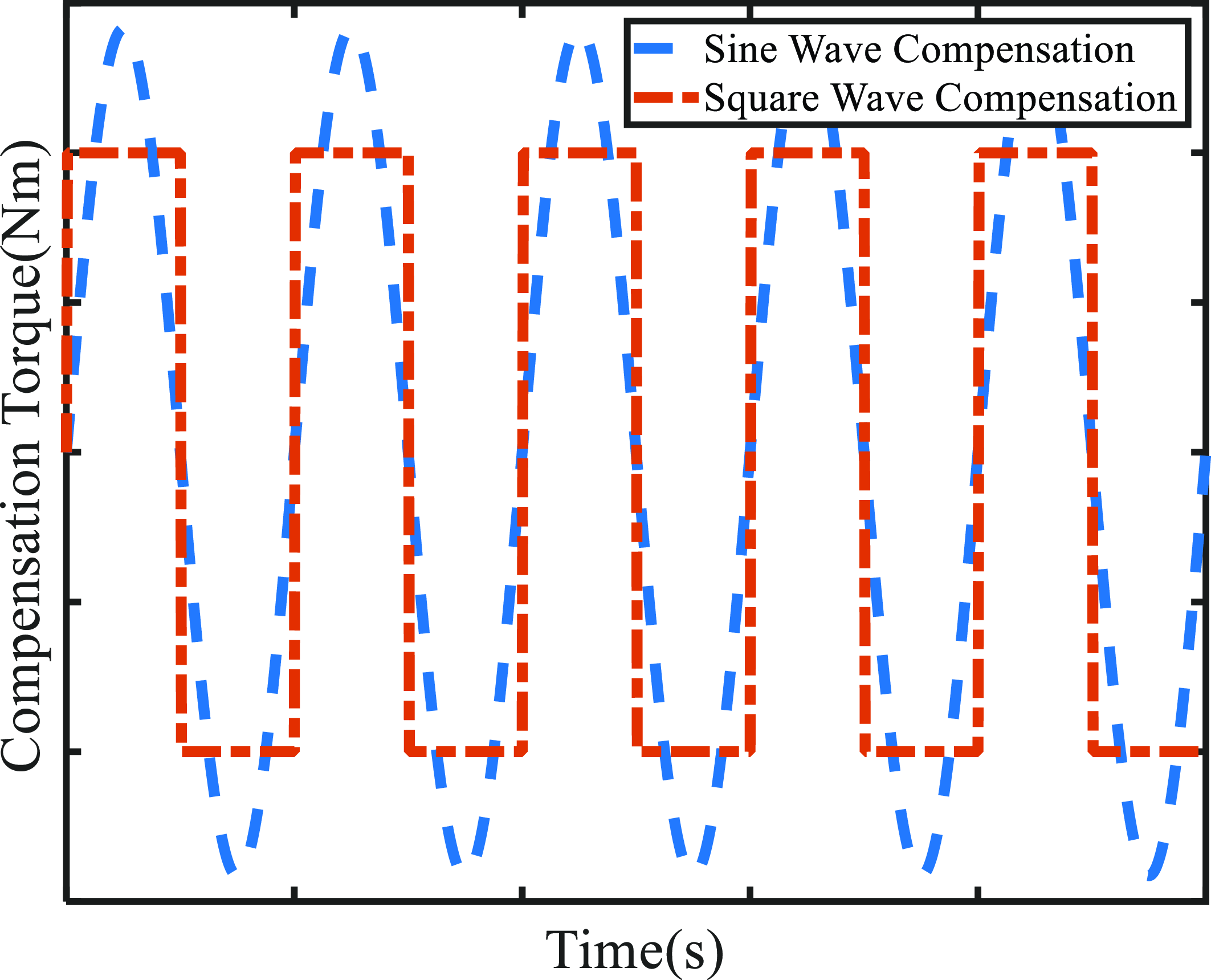
1. The peak value of a sinusoidal waveform compensation is
$\sqrt 2 $
times higher than that of a square wave for the same energy. It is independent of frequency and provides higher accuracy, covering the entire range instead of square wave compensation, which only covers two peak values, as shown in Figure 3.Figure 3.Comparison of sinusoidal compensation and square wave compensation.
-
2. Sinusoidal compensation ensures that the joint motor current is continuous and differentiable, improving the system’s stability. On the other hand, square wave compensation results in discontinuous current, leading to abrupt changes in joint torque, which causes vibrations and noise.
-
3. The compensation torque curve provided by a sinusoidal wave is closer to a true sine wave, which, compared to square wave compensation, can reduce motor energy consumption.


Here, the theoretical basis for Advantage 3 is provided. Assume the current peak values of the sinusoidal compensation and square wave are
 $A$
, the frequency is
 $w$
, and the period is
 $T = 2\pi /w$
. The internal resistance of the motor is
 $R$
. Since the joint is stationary, the motor power is mainly due to thermal loss, with the power formula being
 $P = {I^2}R$
. Then, the power of the square wave compensation over one period
 ${P_{{\rm{square\;}}}}$
is
 \begin{align} P_{square} = \frac{1}{T} \int_{0}^{T} A^{2}Rdt = A^{2}R\end{align}
And the power of the sinusoidal compensation
 ${P_{{\rm{sin\;}}}}$
is
 \begin{align} P_{sin} = \frac{1}{T} \int_{0}^{T} A^{2}\sin^{2}(wt)Rdt = \frac{w}{2\pi}\int_{0}^{\frac{2\pi}{w}} A^{2}\sin^{2}(wt)Rdt = \frac{A^{2}}{2} R \end{align}
From Eqs. (20) and (21), it can be seen that sinusoidal compensation can reduce energy consumption by nearly half.
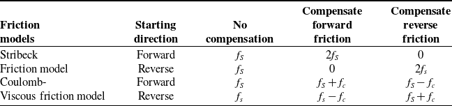
The difference between the starting torque with and without friction compensation for stationary joints is shown in Table II. It can be observed that the effect of using Stribeck identification is superior to the traditional Coulomb-viscous friction model.
Relationship between friction torque and starting torque in different friction models.

When dragging an object, even if the friction compensation direction is the same initially, increasing the starting torque can lead to reverse compensation after half a cycle, causing the joint to move due to the applied force. Since the compensation cycle is brief, this process could be more noticeable. Once the joint starts moving, the maximum static friction compensation for start-up torque compensation will be turned off and switched to the standard Stribeck friction model compensation. A velocity threshold
 $\varPhi$
is set to determine whether the joint is stationary. When the joint’s velocity
 $\left| {\dot q} \right| \lt \varPhi$
, the joint is considered stationary, and sinusoidal compensation for the maximum static friction force is applied. When
 $|\dot{q}| \geqslant \varPhi$
, the joint is considered in motion, and Stribeck friction torque compensation is applied. The friction compensation torque
 $\boldsymbol{\tau}_{{\rm{comp\;}}}$
during the zero-force drag process is
 \begin{align} \tau_{comp} =\begin{cases} f_{s}\sin\!{(wt)} & |\dot{q}| \lt \varPhi \\[3pt] \tau_{f} & |\dot{q}| \geqslant \varPhi \end{cases} \end{align}
4. Experiment
4.1. Gravity identification experiment
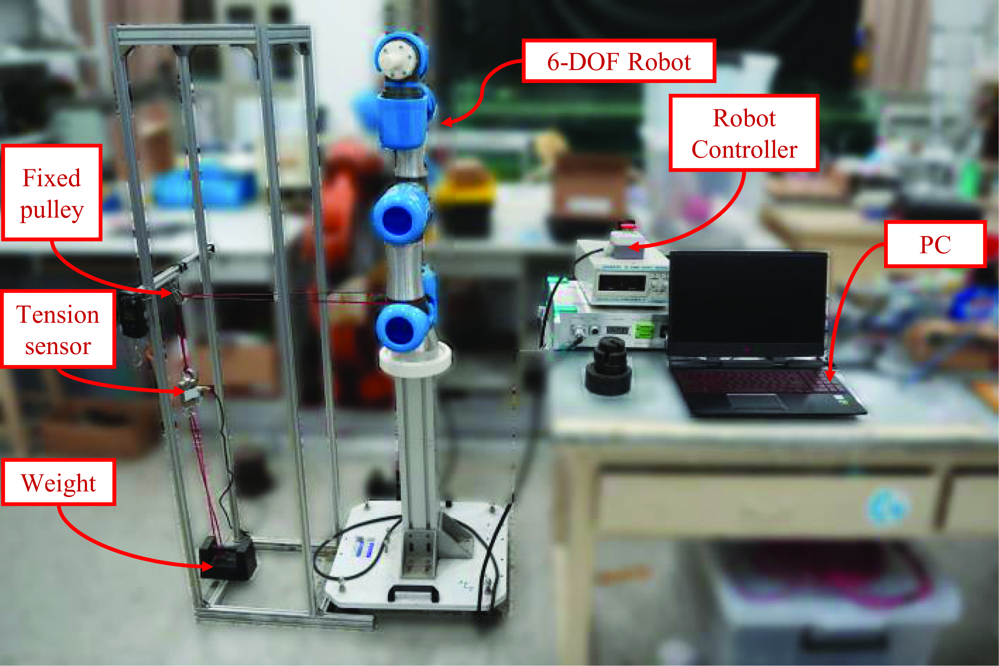
The experimental system is shown in Figure 4. It mainly consists of the six-axis serial robot HM-CR-3, a robot controller, a PC, and a tension sensor. The robot’s MDH parameter table is shown in Table III.
MDH parameters.

Experimental equipment.

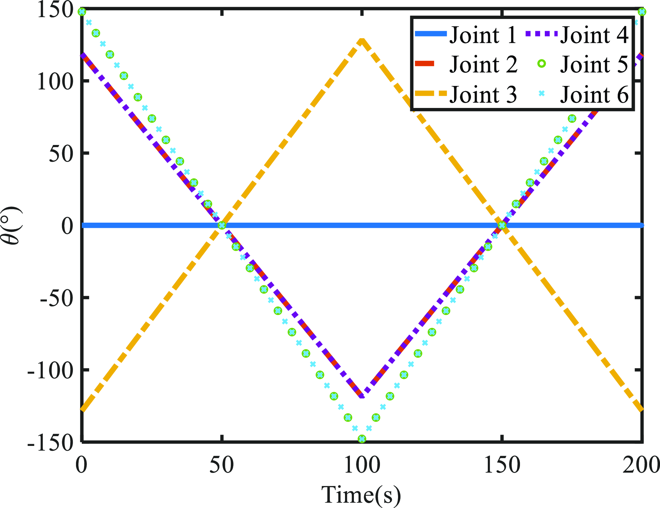
Gravity identification excitation trajectory for each joint.

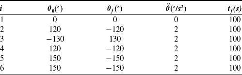
The excitation trajectory during the experiment is shown in Figure 5. The trajectory is designed based on linear interpolation with parabolic transitions. In the excitation trajectory, since joint 1 is mounted vertically and unaffected by gravity, it remains stationary at the origin. Gravity and friction constitute the main components of the driving torque for small- or medium-sized robots. At the same time, since the gravity term of joint
 $i$
’s current includes its driving current and the current induced by subsequent joints, it is necessary to ensure that both joint
 $i$
and the subsequent joints are in motion during driving. Additionally, to facilitate the extraction of gravity current at a constant speed in a symmetrical trajectory, all joints are started and stopped simultaneously, ensuring that each joint is at a constant speed during a specific period to extract the joint gravity current. If each axis does not start and stop simultaneously, it may lead to inaccurate extraction of the gravity term current and increase identification errors.
The trajectory parameters are shown in Table IV.
Trajectory parameters.

The robot follows the designed trajectory repeatedly while continuously recording the angles, angular velocities, and drive currents of each joint in real time. Due to the significant noise in the driving current, a window filter is applied to smooth it out, utilizing a uniform window size of 20. The data for the current in joints 2 to 6, before and after filtering, are displayed in Figure 6.
Experimental current data for joints 2 to 6.

As shown in Figure 6, the current graphs demonstrate a regular pattern, suggesting a relationship between current and torque. This serves as the foundation for parameter identification based on current. The data collected are processed using the Eq. (8) method. As this paper employs a current-based approach, the step-by-step identification results are presented in Table V.
Gravity parameter identification results.

Friction identification excitation trajectory parameters.

4.2. The friction identification experiment
When conducting the friction identification experiment, it is crucial to ensure that only joint
 $i$
is in motion, while the other joints remain stationary. The joint
 $i$
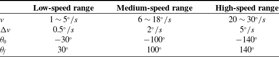
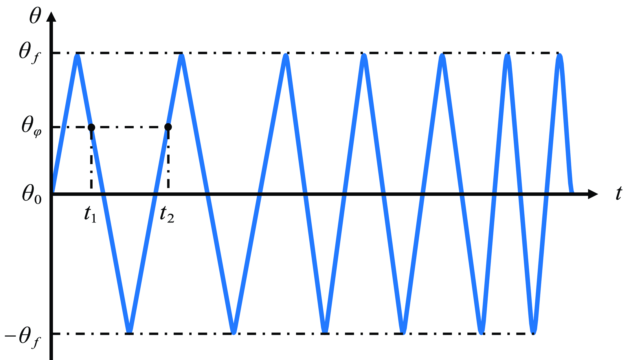
should follow the trajectory shown in Figure 7, with the corresponding joint angle, angular velocity, and driving torque recorded. Due to the complexity of friction at low speeds, it is recommended to use a smaller velocity interval
 ${\rm{\Delta }}v$
to obtain more sampling points in the low-speed range. The specific excitation trajectory parameters are listed in Table VI:
Friction identification trajectory.

The constant velocity segment trajectory data is extracted. The friction torque of the constant velocity segment is extracted according to Eq. (21). The extracted data should be fitted using the Stribeck friction model, with empirical parameters
 $\delta = 2$
. Based on these parameters and Eq. (19), the following expression is obtained:
 \begin{align} f(v) = f_{v}v + f_{c}{\rm sgn}(v) + \left(f_{s} - f_{c}\right)e^{-(|v|/v_{s})} {\rm sgn}(v) \end{align}
The friction model was obtained by iteratively fitting the coefficients by the Levenberg-Marquardt method using
 $ \boldsymbol{p} = \left[ {{f_v},{f_c},{f_s} - {f_c},1/{v_s}} \right]$
as the parameter to be fitted. The fitting results for the friction torque of joint 1 are shown in Figure 8.
Friction model of Joint 1.

In the low-speed range, the friction in Joint 1 exhibits a nonlinear behavior, decreasing as the velocity increases, which aligns with the characteristics of the Stribeck friction model. The same procedure is applied to Joints 2 through 6, resulting in Figure 9.
Friction models of Joints 2 to 6.

4.3. Validation of gravity and friction identification results
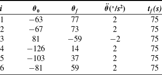
A low-speed motion trajectory is randomly planned to verify the accuracy of the robot’s gravity and friction identification results. The planning method follows Eq. (7)’s requirements, ensuring that all axes start and stop simultaneously to obtain accurate gravity term current. The parameters of the planned trajectory are listed in Table VII.
The time intervals of the trajectory indicate that each joint is in a state of constant low velocity motion. Theoretical currents are calculated using the gravity equation and friction model. Then, compare the theoretical current with the actual operating current. Since Joint 2 is significantly affected by gravity and friction, this comparison of currents provides a more precise illustration. The actual and theoretical currents during the motion of Joint 2 are illustrated in Figure 10.
Validation trajectory parameters.

Joint 2 gravity and friction validation data.

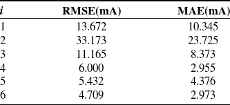
As shown in Figure 10, despite significant noise in the current signal, the theoretical current aligns well with the observed data. After applying a window filter with a length of 20 to the current signal, the theoretical current closely matches the filtered current. Figure 11 displays the sampling data and validation results for the other joints. The accuracy of the fit is assessed using the root mean square error (RMSE) and mean absolute error (MAE), summarized in Table VIII.
Joint 1, 3∼6 gravity and friction validation data.

Fitting results.

According to the data in Table VIII, the average RMSE for each joint is 12.359 mA, and the average MAE is 8.791 mA, with the maximum error being only 33.173 mA. The experimental results suggest that the gravity parameters and friction model identified can accurately compute the robot’s dynamics in a low constant-speed state in real time, based on the angle and angular velocity feedback from the encoder.
4.4. Zero-force dragging start-up torque compensation technique experiment
From the previous friction identification experiment, the maximum static friction force parameters for each axis in the Stribeck friction model can be obtained, as shown in Table IX.
Maximum static friction current for each joint.

Joint 1 was chosen as the experiment object. The joint was tested by moving it from a stationary state to a moving state, both with and without sine wave compensation. A gradual force was applied at the start, and a constant speed was maintained during the movement. The joint angle, angular velocity, and current were recorded during the experiment, as shown in Figure 12. The results in Figure 12 indicate that the angular velocity after friction compensation is smoother, with no sudden peaks or overshoot. The compensated current also shows less variation, demonstrating the effectiveness of reducing the starting torque.
Joint 1 dragging experiment.

When applying sine wave compensation to the joint, it was observed that if the period is too long, the joint may oscillate back and forth. This occurs because, with an extended period, the sine wave compensation current can exactly cancel out the maximum static friction. Due to factors such as gravity, the joint begins to move, and after half a period, the compensation current reverses, causing the joint to move in the opposite direction, leading to oscillations. A compensation period that is too slow can induce oscillations in the robotic arm, while too fast period may reduce the compensation effect. Therefore, selecting an appropriate compensation period is crucial for system stability. Applying sine waves of different periods to Joint 1, the oscillation range and starting torque are recorded to determine the optimal compensation period. This is illustrated in Figure 13.
Sine wave compensation frequencies for each joint.

Comparison of joint compensation algorithm effects.

Effect of sine wave compensation with different frequencies on Joint 1.

As shown in Figure 13, the starting torque is relatively low at low frequencies, but the joint shows noticeable oscillations, indicating periodic movement. As the frequency increases, the oscillation frequency and starting torque increase while the oscillation amplitude decreases, resulting in a more stable robotic arm. Based on the trends in oscillation and starting torque, a frequency of 16 Hz is chosen as the sine wave compensation frequency for Joint 1. At this frequency, the oscillation range is reduced to below
 ${0.06^ \circ }$
, with no significant oscillations, while maintaining a low starting torque. The other joints’ optimal sine wave compensation frequencies are determined using the same experimental method, as outlined in Table X.
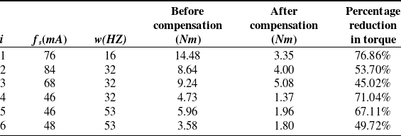
Based on the compensation frequencies for each joint listed in Table X, each joint’s start-up torque compensation effect is verified. The steps are as follows: A force sensor is used to slowly attach a weight, converting the gravitational force into tension through a fixed pulley, and the force required to initiate joint movement is recorded. The starting torque is then calculated by measuring the lever arm, and the starting torque for each joint is measured with and without sine wave compensation. Multiple experiments are conducted for each joint, and the average value is taken. The final measurement results are shown in Table XI.
After implementing the sine wave compensation algorithm, the average starting torque across all joints decreased by
 $60.58{\rm{\% }}$
. Joint 1 experienced the most significant improvement, with a
 $76.86{\rm{\% }}$
reduction in start-up torque, while Joint 3 had the slightest effect, reducing nearly half of the starting torque. Sine wave compensation made the dragging motion much smoother, particularly in small-range movements. Before compensation, it was easy to exert too much force, causing the robot to overshoot its target position. Following compensation, the robot could be dragged efficiently and accurately for precise small-range positioning.
5. Conclusion
-
(1) A method was proposed for identifying the robot’s gravity parameters based on current measurements. This method uses the MDH parameters to obtain the minimal set of gravity parameters and does not require knowledge of the joint reduction ratio or torque coefficient values.
-
(2) The Stribeck friction model accurately described the nonlinear characteristics of joint friction at low speeds for fitting the joint friction torque, providing a more precise representation than the Coulombviscous model.
-
(3) To address the issue of excessive starting torque, an algorithm for torque-based zero-force dragging was introduced. Additionally, a sine wave periodic compensation algorithm based on maximum static friction was proposed to reduce the starting torque successfully.
-
(4) Gravity and friction identification experiments were conducted for the robot, and the identification results closely matched the theoretical current with the actual current. After applying the periodic compensation algorithm, the starting torque of zero-force dragging showed an average reduction of
$60.58{\rm{\% }}$
, resulting in smoother dragging.

6. Symbol definitions
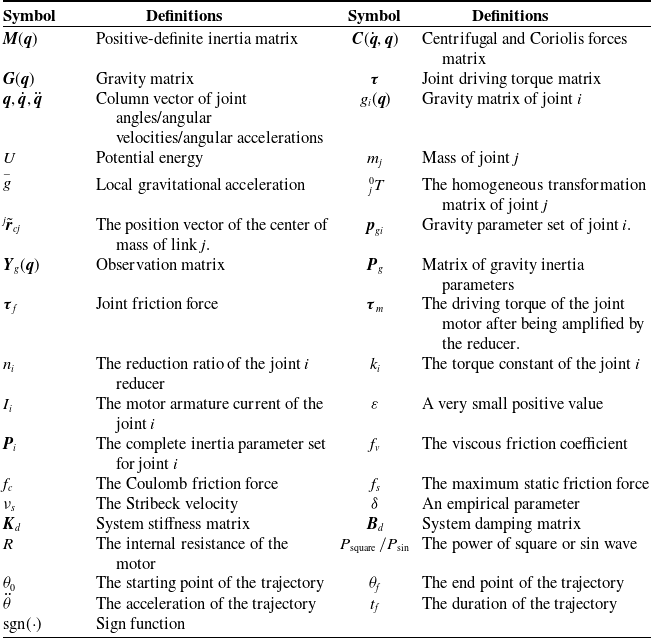
The definitions of the symbols used in this article are listed in the Table XII below.
Symbol definitions.

Author contributions
All authors contributed to the conception, design, and data analysis of this study. Chenggang Li contributed to the design of the study and critically revised the manuscript. Lujin Zhu contributed to the acquisition and interpretation of data and drafted the manuscript. Gang Yang and Junxian Zhang contributed to the data collection and provided critical feedback on the manuscript.
Competing interests
The authors declare no conflicts of interest exist.
Ethical approval
None.