
I. INTRODUCTION
Advanced electrochemical energy storage technologies (i.e., rechargeable batteries) are critical for the future society because they are important for improving the efficiency of electric power grids, stimulating growth of energy generation from renewable resources (wind and solar, etc.), and providing an alternative to fossil fuels for the transportation. Reference Armand and Tarascon1–Reference Yang, Zhang, Kintner-Meyer, Lu, Choi, Lemmon and Liu4 Currently commercialized high-energy-density batteries are based on lithium-ion battery (LIB) technologies integrated with graphite as the anode and metal oxides or phosphates as the cathode. Reference Poizot, Laruelle, Grugeon, Dupont and Tarascon5,Reference Etacheri, Marom, Elazari, Salitra and Aurbach6 This technology can provide high energy density and good power density, and has been successful in powering many types of applications such as mobile devices and electric vehicles. Despite this past success, LIBs have technical limitations to fulfill future needs in stationary energy storage applications. The reasons are growing concerns about the safety of LIBs, their cost, inherent limitations in the energy density that can be achieved, and the scarcity of lithium (Li) resources. These concerns have motivated intensive research investigations during the past decades on advanced battery devices, with the goal of developing systems that are able to provide even higher energy and power densities, significantly reduced manufacturing and maintenance cost, and improved safety and reliability. Reference Goodenough7,Reference Liu8 Significant progress has been made, and prototype devices with excellent performance metrics have been documented in the literature. Some examples of technologies that have been studied are high power supercapacitors, Reference Zhu, Murali, Stoller, Ganesh, Cai, Ferreira, Pirkle, Wallace, Cychosz, Thommes, Su, Stach and Ruoff9–Reference Ghidiu, Lukatskaya, Zhao, Gogotsi and Barsoum11 redox-flow batteries, Reference Janoschka, Martin, Martin, Friebe, Morgenstern, Hiller, Hager and Schubert12,Reference Li, Nie, Vijayakumar, Li, Liu, Sprenkle and Wang13 sodium (Na)-metal halide batteries, Reference Li, Lu, Kim, Meinhardt, Chang, Canfield and Sprenkle14,Reference Li, Lu, Kim, Viswanathan, Meinhardt, Engelhard and Sprenkle15 Na-ion batteries, Reference Yabuuchi, Kubota, Dahbi and Komaba16 and high-energy-density metal based batteries. Reference Yang, Zheng and Cui17,Reference Liu, Leskes, Yu, Moore, Zhou, Bayley, Kim and Grey18
Metallic anodes with low standard redox potentials, such as Li, Na, and magnesium (Mg) are promising electrode materials because of their substantially higher energy densities compared with typical intercalation/conversion-type electrode materials (Table I). Among these metal anodes, Li can provide the highest energy density of 3861 mA h/g with the lowest redox potential (−3.04 V versus standard hydrogen electrode, Table I). However, its use in practical applications is challenging because of safety and reliability concerns. The electrochemical deposition of Li tends to form unsafe dendrites, and it has very limited Coulombic efficiency (CE), which results in poor cycling stability especially when cycled with a high-capacity cathode. Reference Lu, Shao, Lozano, Bennett, Graff, Polzin, Zhang, Engelhard, Saenz, Henderson, Bhattacharya, Liu and Xiao19,Reference Liu, Lin, Liang, Zhao, Yan and Cui20 While exciting progress has been made toward improving the CE of Li through the use of new electrolyte materials, electrolyte additives, and/or new electrode structures, future research still is needed to achieve practical applications. Reference Qian, Henderson, Xu, Bhattacharya, Engelhard, Borodin and Zhang21–Reference Ding, Xu, Graff, Zhang, Sushko, Chen, Shao, Engelhard, Nie, Xiao, Liu, Sushko, Liu and Zhang24
Comparison of key performance parameters for lithium (Li), sodium (Na), and magnesium (Mg). Reference Muldoon, Bucur and Gregory25–Reference Vesborg and Jaramillo31

The use of Mg metal as the anode has unique technological and economic advantages, and has received increasing interests recently. Reference Cheng, Parent, Shao, Wang, Sprenkle, Li and Liu32−Reference Bucur, Gregory, Oliver and Muldoon35 Mg has appreciable energy density (gravimetric 2205 mA h/g, volumetric 3832 mA h/cm Reference Whittingham3 ), lower cost, and much safer compared with Li metal. In addition, electrochemically deposited Mg2+ ions do not form dendritic structures and have nearly 100% CE when operated in recently developed advanced electrolytes. Reference Yoo, Shterenberg, Gofer, Gershinsky, Pour and Aurbach36 These characteristics suggest that Mg metal holds great promise for use in durable and safe energy storage devices. The first rechargeable Mg battery prototype was documented in 2000 by Aurbach et al. using Chevrel-phase Mo6S8 as the cathode material. Reference Aurbach, Lu, Schechter, Gofer, Gizbar, Turgeman, Cohen, Moshkovich and Levi37 The practical application of Mg batteries; however, currently faces several issues, including two major challenges. First, the reversible deposition and stripping of Mg2+ ions require specially synthesized electrolytes that do not form surface passivation layers, which is believed to block Mg2+ ion transport. These electrolytes are usually corrosive and have much narrower electrochemical window compared with LIB electrolytes. Recent developments, particularly on all-phenyl-complex electrolytes, Reference Mizrahi, Amir, Pollak, Chusid, Marks, Gottlieb, Larush, Zinigrad and Aurbach38 all-inorganic electrolytes, Reference Liu, Shao, Li, Gu, Hu, Xu, Nie, Chen, Wang and Liu39−Reference Zhao-Karger, Mueller, Zhao, Fuhr, Jacob and Fichtner42 and nonhalide electrolytes, Reference Tutusaus, Mohtadi, Arthur, Mizuno, Nelson and Sevryugina43,Reference McArthur, Geng, Guo and Lavallo44 have established electrolytes with significantly improved voltage windows and activities. The second major challenge is associated with the lack of high-voltage cathode materials that can provide good Mg2+ insertion/extraction kinetics. Reference Levi, Gofer and Aurbach45 Conventional intercalation cathode materials developed for Li and Na batteries were found to react poorly with Mg2+ ions. This is likely due to the much higher charge density associated with divalent Mg2+ ions, which have stronger coulombic interactions with the host materials and result in poor ionic transport and difficulties in structural stabilization. Reference Liang, Yoo, Li, Shuai, Calderon, Robles Hernandez, Grabow and Yao30,Reference Nam, Kim, Lee, Salama, Shterenberg, Gofer, Kim, Yang, Park, Kim, Lee, Chang, Doo, Jo, Jung, Aurbach and Choi46,Reference Shterenberg, Salama, Gofer, Levi and Aurbach47 Future research is needed to effectively resolve these two challenges for practical Mg batteries.
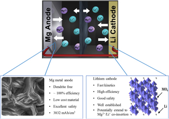
An alternative, but very promising, approach for building practical batteries with Mg-metal anodes is the design of hybrid batteries that use charge carriers other than Mg2+ ions for the cathode reaction. One potential architecture is the use of Li ions in hybrid Mg–Li batteries. The fundamental structure of these batteries is illustrated in Fig. 1.
Schematic illustration of the hybrid Mg–Li battery design. The potential of combining the advantages of Mg metal anode and Li-ion cathode make this design extremely attractive for high rate and reliable batteries. Reference Cheng, Stolley, Han, Shao, Arey, Washton, Mueller, Helm, Sprenkle, Liu and Li41

This design has an Mg metal anode, a Li+ ion intercalation cathode, and a dual-salt electrolyte that has both Mg2+ and Li+ ions solvated in solution. The design integrates the advantages of the Mg metal anode and the Li+ ion intercalation cathode, especially the good reaction kinetics and excellent safety features, in a single device so it can provide much better rate capability and cyclic reliability. It should be noted that Li+ ion intercalation cathodes are not the only option; future developments of this design could include cathodes with other cations such as Na+ ions, dual cation co-intercalation, or anion insertions. Therefore, this design could provide significant opportunities for practical energy storage applications ranging from stationary devices to transportation equipment. In this review article, our goal is to summarize what has been achieved thus far and provide our perspectives on future developments, particularly the critical challenges that should be resolved before this technology can penetrate practical markets. Our paper is organized in three sections. First, we provide a brief summary of the dual-salt electrolytes that have been used in literature. Then, we discuss the performance metrics of prototype devices reported in the literature, with the discussion based on the voltages of the devices reported. Finally, we provide our perspectives and our analysis of the critical challenges.
II. DUAL-SALT Mg–Li ELECTROLYTE: THE PATH TO SUCCESSFUL HYBRID BATTERIES
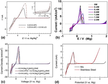
The electrolyte is a key component that plays a pivotal role in rechargeable battery performance. It provides electrochemically active species and determines electrode–electrolyte interfaces for reactions at both the cathode and anode. Development of Mg battery electrolytes had been challenging because simple electrolytes prepared by dissolving a Mg salt in aprotic solvents could not to produce reversible Mg depositions, likely because of the formation of surface passivation layers. Reference Lu, Schechter, Moshkovich and Aurbach48 However, there have been successful demonstrations of several families of electrolytes that are capable of reversible Mg deposition. Gregory et al. initially developed ethereal solutions containing Mg organoaluminates or organoborates that obtained reversible Mg deposition. Reference Gregory, Hoffman and Winterton49 Aurbach et al. later produced electrolytes with an improved anodic stability of ∼2.5 V by reacting Grignard reagents (MgR2, R = ethyl and/or butyl) with Lewis acids (AlEtCl2 or AlCl3). Reference Aurbach, Lu, Schechter, Gofer, Gizbar, Turgeman, Cohen, Moshkovich and Levi37 These were the first prototypes of rechargeable Mg batteries. Since then, this type of electrolyte with the combination of Grignard reagents and Lewis acids has been intensively studied, and its properties have been further optimized. Reference Aurbach, Gizbar, Schechter, Chusid, Gottlieb, Gofer and Goldberg50 For example, combining phenyl magnesium chloride and AlCl3 in tetrahydrofuran (THF) results in all-phenyl-complex (APC) electrolytes with electrochemical windows that exceed 3 V. Reference Mizrahi, Amir, Pollak, Chusid, Marks, Gottlieb, Larush, Zinigrad and Aurbach38 Because of the inherent safety concerns related to Grignard reagents, other Mg compounds such as MgCl2, ROMgCl, and hexamethyldissilazide magnesium chloride (HDMS-MgCl) also have been used as the Mg salts, and electrolytes with excellent electrochemical properties for Mg batteries have been demonstrated. Reference Liu, Shao, Li, Gu, Hu, Xu, Nie, Chen, Wang and Liu39,Reference Doe, Han, Hwang, Gmitter, Shterenberg, Yoo, Pour and Aurbach40,Reference Wang, Guo, Yang, Nuli and Hirano51,Reference Kim, Arthur, Allred, Zajicek, Newman, Rodnyansky, Oliver, Boggess and Muldoon52 These prior works have provided important bases for formulating dual-salt electrolytes that can be used in the design of hybrid Mg–Li batteries. In fact, a general approach for preparing dual-salt electrolytes based on this class of electrolyte involves addition of a Li salt (such as LiCl or LiBF4). Reference Yagi, Ichitsubo, Shirai, Yanai, Doi, Murase and Matsubara53,Reference Cheng, Shao, Zhang, Sprenkle, Liu and Li54 A typical, and probably the most widely used thus far, combination is LiCl dissolved in APC electrolyte (see discussions below). Reference Cheng, Shao, Zhang, Sprenkle, Liu and Li54–Reference Yao, You, Yin, Wan and Guo57 Figure 2(a) shows typical cyclic voltammetry (CV) results for the APC electrolyte with and without addition of LiCl. Reference Yoo, Shterenberg, Gofer, Doe, Fischer, Ceder and Aurbach58 It can be seen that adding LiCl obviously reduced the Mg deposition over-potential and increased the current while maintaining similar anodic stability [the inset in Fig. 2(a)]. Therefore, the addition of LiCl not only provides Li+ ions but also improves the electro-activity for Mg deposition. In the following sections we will provide several examples of the use of this electrolyte in prototype hybrid batteries.
(a–c) Representative electrolytes that have been used to hybrid batteries. (a) Comparison of CV of 0.25 M APC electrolyte with and without 0.5 M LiCl, with platinum as the working electrode and the scan rate was 25 mV/s. Reference Yoo, Shterenberg, Gofer, Doe, Fischer, Ceder and Aurbach58 (b) CV of 0.1 M Mg(BH4)2 dissolved in diglyme with different concentrations of LiBH4 (20 mV/s with platinum electrode). These results are adapted from the work of Shao et al. Reference Shao, Liu, Li, Gu, Nie, Engelhard, Xiao, Lv, Wang, Zhang and Liu59 (c) CV of Mg electrolyte and Mg–Li dual electrolytes (with either LiAlCl4 or 1.0 M LiTFSI) in dimethyl ether (DME). These results are adapted from the work of Cheng et al. Reference Cheng, Choi, Han, Mueller, Zhang, Sprenkle, Liu and Li60 (d) Current collectors stability in Mg electrolyte, the CV of molybdenum (Mo) and stainless steel acquired in 0.2 M shows Mo has remarkable anodic stability that make it suitable for using as the current collector. Reference Cheng, Liu, Shao, Engelhard, Liu and Li61

Mg(BH4)2 and LiBH4 dissolved in ethereal solutions is another family of electrolytes that has been explored for use as dual-salt electrolytes. Reference Shao, Liu, Li, Gu, Nie, Engelhard, Xiao, Lv, Wang, Zhang and Liu59 Figure 2(b) shows the CV of 0.1 M Mg(BH4)2 dissolved in diglyme with different concentrations of LiBH4. The electrochemistry of the electrolyte depends strongly on the ratio of these two salts. With increasing LiBH4 concentrations, the Mg deposition/stripping kinetics were obviously enhanced. The current density also increased and reached a maximum value with 1.5 M LiBH4. Comparison of the solvent effects (THF, DME, and diglyme) and LiBH4 concentration on the CE of Mg stripping/deposition was also studied by Shao et al. The best CE values were observed with digylme as the solvent; it reached nearly 100% when the LiBH4 concentration was >0.6 M. The excellent electrochemical activity of this type electrolyte, together with remarkable stability of diglyme as the solvent (boiling point 162 °C), make them an excellent choice for prototype hybrid batteries with low-voltage cathode materials even though the electrochemical stability window is relatively narrow (∼2.0 V).
Recently, Cheng et al. identified a new dimagnesiumdichloro dimer [DMDC, Mg2(μ-Cl)2(DME)4] cation complex for electrolyte solutions formulated in dimethoxyethane (DME). Reference Cheng, Stolley, Han, Shao, Arey, Washton, Mueller, Helm, Sprenkle, Liu and Li41 This type of electrolyte can be synthesized with a wide range of salt combinations [e.g., MgCl2–AlEtCl2, MgCl2–AlCl3, MgCl2–Mg(TFSI)2] and can produce excellent Mg deposition/stripping kinetics with a wide stability window (>3.4 V versus Mg). This electrolyte material brings exciting opportunities for the design of high-voltage Mg-metal-based batteries. Reference Liu, Shao, Li, Gu, Hu, Xu, Nie, Chen, Wang and Liu39–Reference Cheng, Stolley, Han, Shao, Arey, Washton, Mueller, Helm, Sprenkle, Liu and Li41 Similar to the APC-based electrolytes, dual-salt electrolytes based on DMDC cation complex also can be synthesized by dissolving Li salts. Cheng et al. examined the solubility of different Li salts in the electrolyte prepared by reacting 0.4 M MgCl2 with 0.4 M AlCl3 in DME. Reference Cheng, Choi, Han, Mueller, Zhang, Sprenkle, Liu and Li60 The solubility of the Li salts was found to be very different, and for this particular electrolyte, the highest solubility was observed with LiTFSI [TFSI = bis(trifluoromethane)sulfonamide] that can reach 2.0 M compared to LiAlCl4, LiCl, and LiPF6. The typical electrochemical performance of this type of electrolyte in the presence or absence of Li salt is shown in Fig. 2(c). It is evident that all of these electrolytes have voltage windows that exceed 3.4 V versus Mg, and the reversible deposition and stripping properties of Mg are not affected by the addition of Li salt. In fact, similar enhancements were observed when LiCl was added to APC solution. The high-voltage stability and good Mg electrochemical properties of this electrolyte family make them suitable for studying high-voltage hybrid batteries. Later in this paper, we present some of the recent exciting results.
Finally, we include a brief discussion of the electrochemically stable cathode current collectors that are suitable for Mg batteries. The current collector is an integral part, and it must be stable across the voltage window of the battery. Conventional current collectors, such as aluminum, copper, stainless steel, and nickel, were found to have poor compatibilities with current halide-based high-voltage Mg battery electrolytes. Reference Yagi, Tanaka, Ichikawa, Ichitsubo and Matsubara62 Therefore, the use of this family of electrolytes requires alternative current collectors. Cheng et al. recently identified that both molybdenum (Mo) and tungsten metals have good electrochemical stabilities, and their behaviors were comparable with inert materials including platinum and carbon. Reference Cheng, Liu, Shao, Engelhard, Liu and Li61 Figure 2(d) compares the CV results of Mo and stainless steel in 0.2 M DMDC electrolyte. It is evident that the anodic stability of Mo is comparable with platinum and is much better than stainless steel (around 2 V). The stability mechanism was identified through formation of surface passivation layers. Later, we will discuss examples in which Mo is integrated for high-voltage devices.
A. Low-voltage (<2.0 V) hybrid batteries: show remarkable potentials
The challenges of the limited anodic stabilities of Mg battery electrolytes developed thus far were discussed above, and the electrolytes are in general much less stable when compared with conventional electrolytes for Li-ion batteries and Na-ion batteries. As examples, the APC electrolyte has stability at <3.0 V versus Mg, and the DMDC electrolyte has stability at <3.4 V versus Mg. These stability characteristics limit the voltage windows of the hybrid Mg–Li batteries and introduce significant challenges in developing high-voltage devices. Therefore, it is obvious that low-voltage cathode materials (<2.0 V) must be the starting point for examining the potential of the hybrid cell design. The use of low-voltage materials eliminates side-electrode reactions associated with electrolyte decomposition and facilitates selections for both current collectors (i.e., stainless steel) and cell cases (i.e., coin cells), which can further yield substantial benefits in designing battery architecture.
Chevrel phases, which are good choices for cathode materials, have been studied by several research groups. Reference Cheng, Shao, Zhang, Sprenkle, Liu and Li54,Reference Cho, Aykol, Kim, Ha, Wolverton, Chung, Kim and Cho55 Earlier electrochemical studies by Aurbach et al. clearly demonstrated the preferred intercalation of Li+ over Mg2+ ions and documented much better intercalation kinetics with Li+ ions. Reference Levi, Lancry, Gizbar, Lu, Levi, Gofer and Aurbach63 Cheng et al. recently included Mo6S8 as a cathode material in the battery design with a dual-salt electrolyte (0.4 M APC) and (1.0 M LiCl). Figure 3(a) shows two well-defined Li+ intercalation discharge plateaus at 1.66 and 1.29 V and a specific capacity of 126 mA h/g at 0.1C, which is about the same as the theoretical capacity of Mo6S8 (128.8 mA h/g). Reference Cheng, Shao, Zhang, Sprenkle, Liu and Li54 The electrode reactions under the particular conditions (with high Li+ intercalation kinetics) are.
-
(i) Anode: 2Mg ↔ 2Mg2+ + 4e−.
-
(ii) Cathode: Mo6S8 + 4Li+ + 4e− ↔ Li4Mo6S8.
-
(iii) Overall reaction: 2Mg + Mo6S8 + 4Li+ ↔ Li4Mo6S8 + 2Mg2+.
Mg–Li hybrid batteries with Mo6S8 cathode with electrolytes of APC and LiCl dissolved in THF. (a) Typical charge–discharge profiles at different C-rates with 0.4 M APC and 1.0 M LiCl that shows excellent rate performance of hybrid cells. (b) Cyclic stability profile tested at 10C for 3000 cycles. (c) Typical scanning electron microscope image of the Mg anode showing that no obvious dendritic structures were formed. These results are adapted from the work of Cheng et al. Reference Cheng, Shao, Zhang, Sprenkle, Liu and Li54 (d) Lithiation and magnesiation potential profiles at different Li+ activities (αLi+) determined by combining discrete Fourier transform (DFT) energies with Nernst equation in Mo6S8. Possible Li+ and Mg2+ mixed insertion paths into the Mo6S8 are shown as dashed lines. These results are from the work of Cho et al. Reference Cho, Aykol, Kim, Ha, Wolverton, Chung, Kim and Cho55 (e) Discharge profiles at varying LiCl concentrations that shows the Li-ion concentration plays important role in discharge profiles and capacities.

A stable cycling performance for over 3000 cycles was observed as shown in Fig. 3(b). Post-cycling analysis shows that the main reasons for the capacity decay after 3000 cycles were electrolyte evaporation and corrosion of the current collector. These results indicate a potential for even longer cycling. More importantly, the battery shows outstanding rate capability and a specific capacity of 105 mA h/g was achieved at 10C with only 5% capacity fade. Also, the scanning electron microscope image [Fig. 3(c)] confirmed that the surface of the Mg anode remained dendrite-free after long-term cycling.
The results of DFT analysis [Fig. 3(d)] show energetically preferable occupation sites for the first ion (either Mg2+ or Li+) in the primitive Mo6S8 crystal structure at multiple stage of discharge. Reference Cho, Aykol, Kim, Ha, Wolverton, Chung, Kim and Cho55 Based on the first ion occupied into the structure, various paths of Mg2+ and Li+ can be predicted. Moreover, combining the Nernst equation with the DFT energies determined a threshold Li+ activity (αLi+) value in the electrolyte for lithiation and magnesiation in the Mo6S8 cathode. Cho et al. reported that a dominant reaction in the cathode was governed by Mg2+ insertion rather than Li+ insertion at very low initial Li+ activities. Reference Nam, Kim, Lee, Salama, Shterenberg, Gofer, Kim, Yang, Park, Kim, Lee, Chang, Doo, Jo, Jung, Aurbach and Choi46 In contrast, increasing in Li+ activity leads thermodynamically more favorable lithiation in Mo6S8 rather than magnesiation. Figure 3(e) clearly shows dependence of Li+ concentrations on cell performances in the hybrid system. By controlling the LiCl concentration in the APC electrolyte, they were able to achieve 93.6 and 87.5% of theoretical capacity in the theory-aided design of the hybrid cell systems at the C-rate as high as 20 and 30C, respectively.
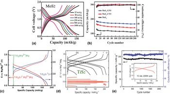
In addition to Mo6S8, several other cathode materials have been studied. Recently, Hus et al. demonstrated experimentally that molybdenum sulfide (MoS2) could be a suitable cathode material for Mg rechargeable batteries. Reference Hsu, Chou, Yang, Lee and Chang64 Figure 4(a) shows the MoS2-based cell has high power capability at various current densities (up to 1000 mA/g). Beside a primitive MoS2, two more MoS2 materials have been examined, such as a MoS2 incorporated with carbon natotubes (MoS2−CNTs) and MoS2 incorporated with graphene and nano-sheets (MoS2−GNSs). It is found that the MoS2−GNS battery can deliver the highest capacity of 225 mA h/g among to the other MoS2 cathodes, and it shows stable cycling performance in a 0.5 M Li+ containing APC electrolyte over 200 cycles, as shown in Fig. 4(b).
Other typical metal sulfides cathodes examined for hybrid batteries. (a–b) Charge–discharge profiles of MoS2 electrodes at different rates in 0.5 M Li+ containing APC electrolyte. The data are adapted from Hsu et al. Reference Hsu, Chou, Yang, Lee and Chang64 Battery performance of a titanium disulfide (TiS2) cathode. (c) The electrolyte was 0.4 M APC-LiCl. The data are adapted from Gao et al. Reference Gao, Han, Zhu, Suo, Luo, Xu and Wang65 (d) Voltage profile of TiS2 cathode and Mg anode at various current densities in a hybrid system. (e) Cycling performance of TiS2 cycled at 1C for 2000 cycles. The data are adapted from Yoo et al. Reference Yoo, Liang, Li and Yao56

TiS2 was introduced as a cathode material for rechargeable magnesium batteries by several groups. Reference Yoo, Liang, Li and Yao56,Reference Gao, Han, Zhu, Suo, Luo, Xu and Wang65 Gao et al. reported a hybrid Mg−Li battery using a Mg anode, a TiS2 cathode, and an APC-LiCl electrolyte, which is stable within the operating voltage window of TiS2 (1.0–1.6 V versus Mg/Mg2+). Reference Gao, Han, Zhu, Suo, Luo, Xu and Wang65 Figure 4(c) shows the results of galvanostatic tests of TiS2 cathodes in three different cells: TiS2|Li+|Li, TiS2|Mg2+|Mg, and TiS2|Li+, Mg2+|Mg. The charge–discharge profiles demonstrated that a reversible Li+ intercalation into TiS2 in the Li+, Mg2+ dual-salt electrolyte takes place in the same manner of that in a Li+ electrolyte. Excellent cycling stability was observed over 400 cycles with no capacity fading (99.5% CE), In addition, these batteries can deliver a specific capacity of 161 mA h/g, which is 32% higher than general Mg-ion batteries.
Yoo et al. also reported a high capacity for hybrid batteries using a TiS2 cathode. Reference Yoo, Liang, Li and Yao56 They have tested the TiS2 cathode against different anode materials, such as a metallic Li and Mg anode, to study cycling stability and the electrodeposition behavior of the anodes during cycling. The rate performance of TiS2 [Fig. 4(d)] shows a high specific capacity of 220 mA h/g at 0.1C. This is by far the highest value reported among conventional Mg−Li hybrid batteries. Figure 4(e) shows the galvanostatic performance of TiS2. TiS2 in dual-salt electrolytes cycled at 1C had a stale cyclability of over 2000 with 99.6% of the CE. Also, the TiS2-based cell is more stable with the Mg anode while the cell with the Li anode eventually resulted in a cell failure due to the dendrite formation.
Titanium dioxide (TiO2) is found to be a possible candidate for rechargeable Mg batteries because of its high capacity and suitable working voltage (0.9 V versus Mg) that matches the electrochemical window of the dual-salt electrolytes system. Reference Su, Huang, NuLi, Tuerxun, Yang and Wang66 Figure 5(a) shows a charge–discharge voltage profile of a commercial TiO2|Mg cycled at 0.2C in a dual-salt electrolyte. It is shown that the TiO2 can deliver a high capacity of >140 mA h/g. Su et al. reported that a Mg−Li hybrid battery with 1D mesoporous TiO2(B) nanoflakes as a cathode and Mg anode in 0.5 M Mg(BH4) and 1.5 M LiBH4 dissolved in tetraglyme (TG) also can be a possible combination that could deliver high capacity with excellent electrochemical performance. Reference Su, NuLi, Huang, Miao, Yang and Wang67 Figures 5(b) and 5(c) show that a TiO2(B) cathode can deliver a charge capacity of 130 mA h/g at 1C and has exceptional long-term (up to 6000 cycles) stability, even at high rates (up to 2C). They proposed that the high capacity is based on pseudocapacitive reactions dominated by a synergic interaction between Mg2+ and Li+ ions.
Typical oxide cathodes examined for hybrid Mg–Li batteries. Electrochemical and battery performance data of several other types of cathode materials for hybrid Mg–Li batteries, where significantly increased capacity, rate capability, and cyclic stability have been observed with the hybrid design. Charge−discharge profile of (a) commercial TiO2 and (b, c) one-dimensional mesoporous TiO2 nanoflakes in 0.5 M Mg(BH4)2 and 1.5 M LiBH4 in tetraglyme. The data are adapted from Su et al. (d) Charge−discharge profile and (e) cyclic stability profile of Li4Ti5O12 cathode in the electrolyte of 0.4 M APC + 1.5 M LiBH4. The data are adapted from Miao et al. Reference Miao, NuLi, Wang, Yang, Wang and Hirano68 (f) Charge/discharge profile of MoO2 in dual-salt electrolyte and the improvement of its activity through using new structures of hollow microspheres. Reference Pan, Liu, Miao, Yang, Wang, Nuli and Hirano69 (g–i) are adapted from Wu et al. Reference Wu, Yang, Yao, Yin, Gu and Guo70

Li4Ti5O12 (lithium titanium oxide, LTO) has been studied as an anode material for Li-ion batteries because its lattice dimensions do not change upon lithiation/delithiation. Although LTO has known to be a zero-strain for Mg-ion insertion, Mg2+ electrochemical insertion into LTO is a kinetically sluggish reaction and has strong size dependence. Miao et al. reported an effect of dual-salt electrolytes on an Mg−Li hybrid battery, consisting of an LTO cathode and Mg anode. Reference Miao, NuLi, Wang, Yang, Wang and Hirano68 Two different LTO cathodes (made from commercially available LTO and simple ball-milled LTO with graphene = LTO/G) against Li or Mg anodes in two different electrolytes [Mg(BH4)2-based mixed electrolyte and APC-based mixed electrolyte] were tested. LTO in the APC-based electrolyte showed slightly better cycling performance than the LTO in the Mg(BH4)2-based electrolyte because of higher electronic conductivity and the low over-potential of the APC-based electrolyte for Mg dissolution/deposition than Mg(BH4)2-based mixed electrolyte, as shown in Figs. 5(d) and 5(e). In addition, the LTO/G batteries show higher capacities with better cycling stability because of higher specific surface area of graphene, which facilitates fast electron transport in the LTO structure.
Figures 5(g) and 5(h) show voltage profiles and rate performances of LTO at various Li+ concentrations in dual-salt electrolyte. Reference Wu, Yang, Yao, Yin, Gu and Guo70 The data shows the electrochemical performance of the LTO electrode is highly dependent on the Li+ concentration, and can be improved significantly by increasing the Li+ ion concentration in the hybrid system. Moreover, a theoretical DFT calculation suggests that co-insertion of Mg2+ and Li+ ions into the LTO is possible at the optimized Li+ ion concentration, which is up to 0.5 M in the experimental condition. High-angle annular dark field and annular bright field scanning transmission electron microscopy images confirmed the co-existence Mg2+ and Li+ phases [Fig. 5(i)] in LTO. Reference Wu, Yang, Yao, Yin, Gu and Guo70
Because of its stable chemical and thermal properties, molybdenum dioxide (MoO2) has been introduced as an attractive cathode material for Li-ion batteries. Reference Shi, Guo, Corr, Shi, Hu, Heier, Chen, Seshadri and Stucky71 Pan et al. synthesized hollow microspheres consisting of MoO2 nanoparticles (denoted as MoO2-HMS), and the combination of Mg anode with MoO2 cathode was evaluated in a dual-salt electrolyte (0.4 M APC and 1 M LiCl, dissolved in THF). Reference Pan, Liu, Miao, Yang, Wang, Nuli and Hirano69 They found that co-insertion of Mg2+ and Li+ into MoO2-HMS occurs in the intercalation reaction. Figure 5(f) shows MoO2-HMS significantly improved electrochemical performance with 100% CE in comparison with the commercial MoO2. Also, the morphological feature of MoO2-HMS positively enhances performance.
B. Conversion-type cathodes
The intercalation compounds have relatively low specific capacity as cathode materials; for example, the Chevrel-phase Mo6S8 cathode discussed above has a theoretical capacity of only 122 mA h/g. FeS2 and FeS, two typical resource-abundant materials with theoretical capacities of 894 and 609 mA h/g, respectively, have been investigated as a conversion-type electrode in Mg based batteries. Reference Zhang, Xie, Han and Li72 Although FeS2 has been tested as a Li battery cathode in the past, its high capacity is seriously counteracted by the dissolution of polysulfide (PS) intermediates as well as Li-dendrite growth, resulting in a fast capacity-fade during cycling. Compared to FeS2, FeS conversion is less complex with expected better in common non-aqueous electrolytes owing to the absence of anionic redox process. By displacing metallic Li by Mg anode and using dual-salt electrolytes with optimized Mg2+ and Li+ concentration, high reversible Li-driven conversion and Mg plating/stripping without any cathode decoration and unsafe Li-dendrite formation are expected.
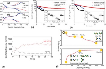
With optimized Li salt concentrations in dual-salt electrolytes, Zhang et al. demonstrated better reversibility from Mg/FeS2 and Mg/FeS chemistries than Li/FeS x . Reference Zhang, Xie, Han and Li72 The Mg/FeS x materials delivered maximum reversible capacities of 600 and 520 mA h/g at 0.05C [Figs. 6(a) and 6(b)], respectively, with in situ formation of solid electrolyte interphases on both the sulfide and Mg surfaces, which effectively mitigate PS dissolution, shuttle phenomenon, and anode passivation. Between two common dual-salt electrolytes, APC coupled with LiCl and Mg(BH4)2 with LiBH4, borohydride-based electrolyte showed better capacity retention of Mg/FeS x batteries than chloride-based electrolyte. Cycling performances of Mg/FeS x batteries using borohydride-based electrolytes with 1.5 M LiBH4 with a cutoff voltage <1.7 V that favor suppression of soluble PSs are shown in Fig. 6. As shown in Figs. 6(c) and 6(d), the reversible capacities at 0.1C lie between 350 and 400 mA h/g after 50 cycles, and are preserved at >200 mA h/g after 150–200 cycles, respectively, for both the sulfides.
Galvanostatic charge–discharge curves of (a) FeS2 and (b) FeS as conversion cathodes by using a borohydride-based electrolyte with 1.5 M LiBH4 during the first six cycles at 0.05C. Discharge capacities of (c) Mg/FeS2 and (d) Mg/FeS batteries as a function of cycling number at 0.1C by using a borohydride-based electrolyte with 1.5 M LiBH4. The cycling stability of discharge capacities of Li/Mg(BH4)2–LiBH4/FeS x and Li/LiPF6/FeS x batteries is also plotted as a comparison. Data adapted from Zhang et al. Reference Zhang, Xie, Han and Li72 (e) Cycling stability of the Mg/S battery in electrolyte with and without LiTFSI and (f) working mechanism of the Mg/S battery with LiTFSI additive. Data adapted from Gao et al. Reference Gao, Noked, Pearse, Gillette, Fan, Zhu, Luo, Suo, Schroeder, Xu, Lee, Rubloff and Wang73

Alternatively, sulfur as a high-capacity (1675 mA h/g) cathode material has attracted great interest in Li−S and Na−S systems. Realization of an Mg/S battery is also of great interest due to its high theoretical capacity of 957 mA h/g from a full cell with a voltage of 1.77 V. Unfortunately, the magnesium organohaloaluminate electrolyte that allows reversible Mg deposition is synthesized by an in situ reaction between Lewis acid (AlCl3) and nucleophilic Lewis base (RMgCl), which reacts with the sulfur. Therefore, to circumvent such incompatibility, Kim et al. proposed a new electrolyte system using non-nucleophilic hexamethyldisilazide magnesium chloride (HMDSMgCl). Reference Kim, Arthur, Allred, Zajicek, Newman, Rodnyansky, Oliver, Boggess and Muldoon52 That system was the first proof-of-concept Mg/S battery, but it lost 70% of its storage capacity at the second discharge. More recently, Zhao-Karger et al. developed a novel non-nucleophilic electrolyte based on magnesium-bis(hexamethyldisilazide) [(HMDS)2Mg]; however, despite the two discharge plateaus at 1.5 and 0.7 V during initial sulfur reduction, no plateau was observed in subsequent cycles. Reference Zhao-Karger, Zhao, Wang, Diemant, Behm and Fichtner74 Consequently, no rechargeable Mg/S battery has been demonstrated yet, mainly due to the electrochemical inactivity of the formed lower-order PSs (Mg-PS) toward oxidation. To enhance the reversibility of Mg/S reaction, Gao et al. used non-nucleophilic Mg electrolytes with a LiTFSI additive that enabled conjugation of a reversible PS redox reaction on the cathode with Mg deposition/stripping on the anode. Reference Gao, Noked, Pearse, Gillette, Fan, Zhu, Luo, Suo, Schroeder, Xu, Lee, Rubloff and Wang73 The electrolyte cycling stability with and without LiTFSI additive is shown in Fig. 6(e), where the sulfur cathode shows a rapid capacity-drop in the Mg-only electrolyte, while the presence of Li+ dramatically improves the reversibility with a stable capacity of ∼1000 mA h/g over 30 cycles, with specific capacity comparable to the Li/S system.
The effect of Li+ on the anode-side, surface chemistry of Mg anodes after cycling in electrolytes with and without LiTFSI were analyzed using x-ray photoelectron spectroscopy analysis. Reference Gao, Noked, Pearse, Gillette, Fan, Zhu, Luo, Suo, Schroeder, Xu, Lee, Rubloff and Wang73 In an Mg-only electrolyte, MgS formed from exposure to dissolved sulfur species. When LiTFSI is added, the x-ray photoelectron spectroscopy spectrum indicates the absence of MgS in the electrolyte. From an Mg-metal corrosion experiment to explore the effect of Li+ on the solubility of short-chain Mg-PS species, the surface layer of MgS was dissolved by the action of Li+, and the Mg surface could not be passivated anymore. To confirm whether MgS is indeed dissolved, inductively coupled plasma optical emission spectroscopy (ICP-OES) analysis was performed in tetraethylene glycol dimethyl ether (TEGDME) solution after the corrosion experiment. The concentration of Mg in the TEGDME was negligible when no Li+ was present, indicating negligible presence of Mg/PS in the TEGDME. However, the concentration of Mg increased by three orders of magnitude in the presence of Li+ after 12 h of LiTFSI addition. As shown in Fig. 6(f), two possible mechanisms for Li+ enhancement of reversibility are suggested: (i) Li+ participates in the cathode reaction to form readily rechargeable Li/PS or incorporates into Mg/PS to form hybrid Mg−Li/PS during discharge, or (ii) the hard Lewis acid Li+ strongly coordinates to the surface S2−of lower-order Mg-PS, hence enhancing its solubility, decreasing its oxidation energy barrier, and making it electrochemically active. Although further studies are needed, the new scientific insights obtained so far will pave the path for the realization of practical conversion-type rechargeable Mg/S battery.
C. High-voltage (>2.0 V) hybrid devices: required for practical applications but are facing great challenges
The energy density of a battery is proportional to its voltage and therefore, one of the most important approaches producing high-energy-density devices is through the use of high-voltage cathode materials. As discussed above, designing high-voltage hybrid Mg–Li batteries faces significant challenges because of poor control over the cathode-electrolyte interface and the limited stability of the electrolyte. These characteristics lead to low CE due to decomposition of the electrolyte (either solvents or salts, or both), poor selectivity of the cathode reactions, and sluggish ion de-solvation and transport across the interface. These challenges are shown in Fig. 7(a) with the CV profile of LiFePO4 (LFP) obtained in a THF electrolyte containing APC and LiBF4. Reference Yagi, Ichitsubo, Shirai, Yanai, Doi, Murase and Matsubara53
Realization of high-voltage batteries requires both advanced electrolyte and cell architecture design, (a) CVs of LFP in conventional APC-based electrolytes show relatively poor efficiency (results adapted from Yagi et al. Reference Yagi, Ichitsubo, Shirai, Yanai, Doi, Murase and Matsubara53 ) whereas the same material in (b) (advanced electrolyte) shows excellent efficiency but with even higher voltage cathodes. (c) The efficiency for LMO is poor. (d) Rate capability of LFP. The results are adapted from Cheng et al. Reference Cheng, Choi, Han, Mueller, Zhang, Sprenkle, Liu and Li60

Intercalation of Li+ ions was clearly observed and was the dominant reaction (after comparing with the nearly no activity of pure APC electrolyte). Substantial anodic currents corresponding to electrolyte decomposition at voltages beyond 2.5 V also were observed. As a result, prototype batteries based on this system had low efficiency and limited reversible capacity. This is clear evidence that developing new electrolytes with better stability are necessary.
On the basis of the DMDC electrolyte established recently (see discussions above), Cheng et al. examined the use of this electrolyte in the design of high-voltage hybrid batteries. Reference Cheng, Choi, Han, Mueller, Zhang, Sprenkle, Liu and Li60 Figures 7(b) and 7(c) shows the CV profiles of LFP and LiMn2O4 (LMO) in this electrolyte. The LFP exhibited a set of well-defined redox peaks that are characteristic of Li+ ion intercalation. Furthermore, this result also suggests that the electrolyte was stable over the voltage window of LFP, and no obvious electrolyte decomposition was observed. Therefore, this electrolyte has good stability and has advantages over the APC electrolyte for LFP. The behavior of LMO, on the other hand, showed two sets of redox peaks that correspond to Li+ ion intercalation. However, the redox potentials of LMO are close to the electrolyte decomposition (as suggested by the sharp increases in anodic current beyond 3.4 V); hence, the efficiency of prototype batteries was low. Cheng et al. demonstrated an assembly of prototype hybrid batteries with the LFP cathode using a Swagelok cell and Mo rods for the cathode current collector. Reference Cheng, Choi, Han, Mueller, Zhang, Sprenkle, Liu and Li60 It is worth noting here that such a design ensures good sealing and electrochemical stability. The LFP cathode studied in this work was fabricated as a free-standing film using the rolling method and polytetrafluoroethylene as the binder. The active material loading was ∼10 mg/cm2, and such a high loading is compatible with practical applications. Figure 7(d) shows a set of charge–discharge profiles of prototype batteries at rates ranging from 0.1 to 1.0C (1C = 170 mA/g). The cell exhibited voltage profiles similar to those of cycled Li cells. The electrode was able to deliver an outstanding capacity of 140 mA h/g at a rate of 0.1C. The reversible Li intercalation was confirmed with x-ray diffraction analysis. In addition, the cell had good rate performance, and the capacity at 1C was ∼120 mA h/g. The cyclic stability also was good, with capacity retained ∼90 mA h/g after 100 cycles.
High-voltage devices can also be designed using a solid electrolyte separator with different electrolyte chemistries for the cathode and anode reactions. Figure 8(a) shows a design using Grignard-based electrolyte as the Mg anode electrolyte (1 M PhMgBr and 0.1 M LiBr in THF), and 0.5 M Li2SO4 aqueous solutions as the cathode electrolyte. Reference Chang, Yang, Wang, Li, Fu, Wu and Holze75 Figure 8(b) shows the charge–discharge profile of this type of hybrid battery, which demonstrated good reversibility and delivered a capacity of 121.7 mA h/g with an output voltage of 2.1 V. The cyclic stability profile for 20 cycles is shown in Fig. 8(c), and the battery had 10% capacity after 20 cycles. The efficiency was less than 100%, which was due to the low efficiency for Mg plating-stripping in the Grignard reagent. In another study, Zhang et al. assembled a stable high-voltage battery using flexible pyrolytic graphitic film as the current collector and a pouch cell configuration (instead of a coin cell). Reference Zhang, Xu, Cui, Hu, Chai, Du, He, Zhang, Zhou, Han, Cui and Chen76 The electrolyte used in this work was 0.5 M APC and 0.4 M LiCl. Figure 8(d) shows typical charge–discharge profiles at different C-rates. The cell delivered an initial capacity of 156.4 mA h/g at 0.15C and a discharge plateau of 2.45 V. The discharge capacities at different C-rates were 144.1, 123.2, 96.6, and 68.8 mA h/g at 0.3, 0.6, 1.2, and 3.0C, respectively. In addition, this work demonstrated the capability of the cell to operate at a low temperature of −40 °C. The cyclic stability test shows that this hybrid cell had capacity retention of 98% after 200 cycles at 0.1C.
Approaches for high-voltage hybrid batteries. (a–c) New architectures using a solid-state separator and an aqueous electrolyte for cathode reaction. (b) Charge−discharge profile. (c) Cyclic stability. Data are adapted from Cheng et al. Reference Cheng, Choi, Han, Mueller, Zhang, Sprenkle, Liu and Li60 (d) Charge−discharge profiles of LFP cells (as punch cells) with flexible pyrolytic graphite fiber current collector and APC-LiCl as the electrolyte. Data from Cheng et al. Reference Cheng, Choi, Han, Mueller, Zhang, Sprenkle, Liu and Li60 (e–f) The use of Prussian blue analogues (PBA) as cathodes in APC-LiCl electrolyte. (e) Charge-discharge profiles of vacuum-dried PBA with different concentrations of LiCl. (f) Comparison of cyclic stability of PBA prepared as either hydrated or vacuum-dried form. Data from Chang et al. Reference Chang, Yang, Wang, Li, Fu, Wu and Holze75 (g–i) Data from Itchitsubo et al. Reference Ichitsubo, Okamoto, Kawaguchi, Kumagai, Oba, Yagi, Goto, Doi and Matsubara77

Sun et al. examined the use of PBA compounds as the cathodes for hybrid batteries. Reference Sun, Duffort and Nazar78 They studied the behavior of hydrated and vacuum-dried PBA (Fe[Fe(CN)6]0.95·2.3H2O and Fe[Fe(CN)6]0.95·0.7H2O, respectively) with an APC-LiCl electrolyte. Figure 8(e) shows the charge–discharge profile of the vacuum-dried PBA at varied concentrations of LiCl. The specific capacity was found to depend strongly on the LiCl concentration, and the maximum capacity was reached to 125 mA h/g with 0.5 M LiCl. Similar results were obtained with hydrated PBA. Figure 8(f) compares long-term cycling stability of both hydrated and vacuum-dried PBA at 200 mA/g. The vacuum-dried sample showed a capacity-drop during the first 10 cycles and then stabilized at 65 mA h/g for up to 300 cycles with 99% CE. In contrast, the hydrated sample had a faster capacity-decay and only retained 55 mA h/g after 300 cycles. The results demonstrated in this work are encouraging and could bring exciting opportunities for applying the PBA cathode for hybrid cell design.
Ichitsubo et al. examined the design of “rocking-chair type” hybrid batteries. Reference Ichitsubo, Okamoto, Kawaguchi, Kumagai, Oba, Yagi, Goto, Doi and Matsubara77 They studied the properties of spinel oxide MgCo2O4 for co-intercalation of Mg2+ and Li+ ions. Reference Ichitsubo, Okamoto, Kawaguchi, Kumagai, Oba, Yagi, Goto, Doi and Matsubara77 Figure 8(g) shows the CV with a chronoamperometry profile for Li insertion/extraction processes into MgCo2O4. They reported that Mg and Li co-insertions can occur in the host MgCo2O4, and these cations then can be reversibly extracted during a charge process. The observed equilibrium redox potentials for the insertion/extraction of Mg and Li cations are estimated to be about 2.9 V versus Mg2+/Mg (3.4 V versus Li+/Li in the reverse extraction) and 3.1 V versus Li+/Li (3.2 V versus Li+/Li in the reverse extraction), respectively. Figure 8(h) shows the cell voltage versus capacity curve obtained for a Mg–Li dual-salt battery in a three-electrode cell, which has Mg49Li51 alloy in atomic ratio as the anode material, a ternary ionic liquid of (Li10/Mg10/Cs80)-TFSI (atomic ratio of cations) for the electrolyte, and a Li reference electrode. In this case, surprisingly the anodic dissolution of the Mg–Li alloy can occur at reasonably low potentials between 0.5 and 0.6 V versus Li+/Li in the reverse extraction (note that the anodic dissolution potential is much lower than the potential (1.5 V versus Li+/Li in the reverse extraction) of the passivated Mg electrode. By taking advantage of an Mg–Li alloy anode and co-intercalation of Mg and Li, they proposed a rocking-chair-type, Mg−Li, dual-salt battery that does not require accretive electrolytes. Figure 8(i) shows predicted discharge–charge processes of the rocking-chair-type, Mg–Li, dual-salt battery.
III. SUMMARY AND PERSPECTIVES
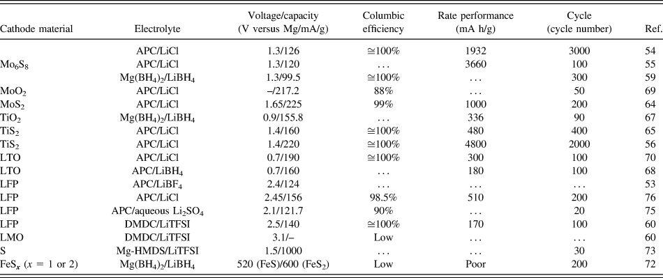
Mg−Li hybrid batteries have unique advantages of combining the Mg-metal anode and well-studied Li+ ion intercalating cathodes (Table II). As reported in the literature, Mg−Li hybrid batteries typically present faster battery cycling performance (higher C-rate) when compared with pure Mg batteries. Cheng et al. reported that the capacity is close to the theoretical value at low C-rates (126 mA h/g at 0.1C) and the high-capacity retention ratios at increased C-rates (102 mA h/g at 15C) for Mg−Li/Mo6S8 hybrid cells. Reference Cheng, Shao, Zhang, Sprenkle, Liu and Li54 In contrast, much lower (80 mA h/g at 0.1C) capacity was observed for Mg/Mo6S8 cell. Yoo et al. also reported the specific capacity of a TiS2 electrode could be increased to 220 mA h/g in Mg−Li/TiS2 hybrid cells. Reference Yoo, Liang, Li and Yao56 However, the capacity of the TiS2 electrode measured in pure Mg electrolyte (without Li+ ions in the electrolytes) is less than 20 mA h/g. Nevertheless, Mg−Li hybrid cells overcame the sluggish kinetics of Mg2+ ion diffusion in cathode materials, which are mainly the result of strong interactions between Mg2+ ion and the cathode host lattice.
Summary of performance metrics of typical prototype hybrid Mg/Li-ion batteries developed by far.

High CE and stable cycling performance were typically observed for Mg−Li hybrid batteries. In recent work, the cycling stability of Mg−Li/Mo6S8 hybrid batteries was studied with a 3000-cycle charge–discharge test conducted at a high rate of 10C. The Mg−Li/Mo6S8 hybrid cell was very stable, with close to 100% CE for each cycle and only 5% capacity fading after 3000 cycles. Reference Cheng, Shao, Zhang, Sprenkle, Liu and Li54 Yoo et al. carried out more detailed mechanism studies by comparing an Mg−Li/TiS2 hybrid battery to a Li/TiS2 battery. Reference Yoo, Liang, Li and Yao56 They observed that the Li anode retrieved from a cycled Li/TiS2 battery was covered with a 100 μm thick, mossy layer composed of a mixture of Li particles and solid electrolyte interphase. In contrast to a Li/TiS2 cell, the Mg anode obtained from a cycled Mg−Li/TiS2 hybrid battery revealed a single-layer of polyhedral Mg deposits due to the hexagonal close packed structure of Mg metal. Indeed, the Mg−Li/TiS2 hybrid battery showed very stable capacity retention and high CE over 300 cycles. Taking all of these observations into consideration, Yoo and co-workers concluded that the superior cell performance of the Mg−Li/TiS2 hybrid battery versus the Li/TiS2 battery is due to the absence of dendritic growth in the Mg anode at practical current density (2 mA/cm2) and mass loading (1 mA h/cm2).
Because of the unique charge/discharge processes of Mg−Li hybrid batteries, where Mg2+ and Li+ ions are used asymmetrically on the Mg anode and Li cathode, dual-salt electrolytes must be able to supply/receive sufficient Mg2+ and Li+ ions throughout the cycling processes. Depending on the Li cathodes used, Mg–Li hybrid batteries can be briefly divided into two categories: (i) those using lithiated cathode materials, such as LFP, LMO, etc., and (ii) those using delithiated cathode materials, such as Mo6S8, TiS2, TiO2, etc. In this review, we focus our discussion on lithiated cathode materials. When using lithiated cathode materials, the Mg–Li hybrid battery starts with the charging process because the battery is assembled in the discharged state. During the charging process, the dual-salt electrolytes have to supply enough Mg2+ ions for depositing on the anode and then accept Li+ ions de-intercalated from lithiated cathode materials. For the discharging process, dual-salt electrolytes accepted Mg2+ ions stripped from the Mg anode and supply Li+ ions for intercalating into the de-lithiated cathode. Identifying charge/discharge processes and involved charge carriers are critical for calculating the specific energy density of Mg−Li hybrid batteries. For example, the active Mg2+ species presented in recent work by Cheng et al. on Mg−Li/LFP hybrid batteries is identical to DMDC, and the charging process of Mg−Li/LFP hybrid batteries can be described as follows Reference Cheng, Choi, Han, Mueller, Zhang, Sprenkle, Liu and Li60 :
 $${\rm{Anode}}:1/2\left[ {{\rm{M}}{{\rm{g}}_2}{\rm{C}}{{\rm{l}}_2}} \right]{\left[ {{\rm{AlC}}{{\rm{l}}_4}} \right]_2} + 2{{\rm{e}}^ - } \Rightarrow {\rm{Mg}} + {\rm{C}}{{\rm{l}}^ - } + {\rm{AlCl}}_4^ - \quad .$$
 $${\rm{Cathode}}:2{\rm{L}}{{\rm{i}}_2}{\rm{FeP}}{{\rm{O}}_4} \Rightarrow 2{\rm{FeP}}{{\rm{O}}_4} + 2{\rm{L}}{{\rm{i}}^ + } + 2{{\rm{e}}^ - }\quad .$$
Full reaction for the charging process:
 $$2{\rm{L}}{{\rm{i}}_2}{\rm{FeP}}{{\rm{O}}_4} + 1/2\left[ {{\rm{M}}{{\rm{g}}_2}{\rm{C}}{{\rm{l}}_2}} \right]{\left[ {{\rm{AlC}}{{\rm{l}}_4}} \right]_2} \Rightarrow 2{\rm{FeP}}{{\rm{O}}_4} + {\rm{LiCl}} + {\rm{LiAlC}}{{\rm{l}}_{\rm{4}}} + {\rm{Mg}}\quad {\rm{.}}$$
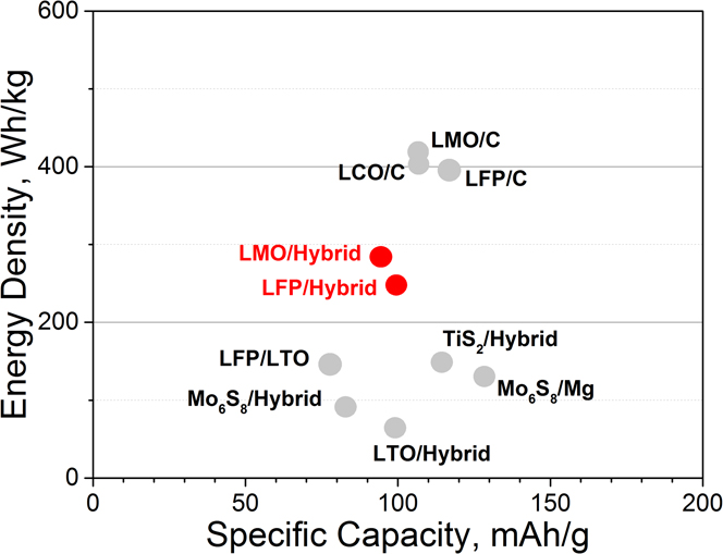
Based on the full reaction Eqs. (1)–(3), the specific energy density of Mg−Li/LFP hybrid batteries along with other Li cathode materials are shown in Fig. 9.
Specific energy density comparison for Mg/Mo6S8 battery, LIB, and Mg–Li hybrid batteries without considering the mass of solvents. Reference Cheng, Choi, Han, Mueller, Zhang, Sprenkle, Liu and Li60

As shown in Fig. 9, a Mg−Li/LFP hybrid battery can deliver a theoretical energy density up to 246 Wh/kg, which is considerably higher than the energy density (134 Wh/kg) of the conventional pure Mg battery using Mo6S8, and the energy density (∼143 Wh/kg) of the LTO/LFP system. The higher energy density of the Mg−Li/LFP battery leads to a higher output voltage (∼2.5 V), which is significantly higher than 1.2 V output voltage of the Mg/Mo6S8 battery and ∼1.9 V of the LTO/LFP battery. Reference Cheng, Choi, Han, Mueller, Zhang, Sprenkle, Liu and Li60
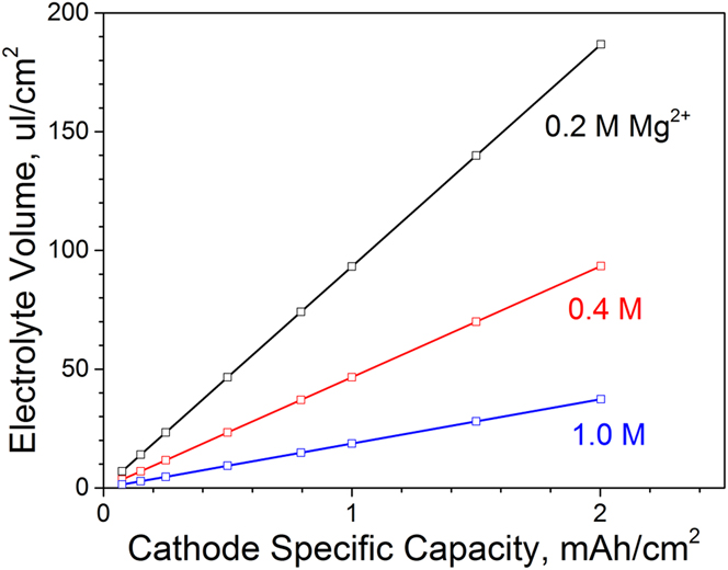
Assuming all Mg2+ ions are supplied from dual-salt electrolytes, the amount that Mg2+ ions in the dual-salt electrolyte should match the capacity of the Li cathode. The minimum amount of required dual-salt electrolyte can be determined as
 $${V_{\rm{h}}} = {{3600000 \cdot {C_{{\rm{Li}}}}} \mathord{\left/ {\vphantom {{3600000 \cdot {C_{{\rm{Li}}}}} {zF{C_{{\rm{Mg}}}}}}} \right. \kern-\nulldelimiterspace} {zF{C_{{\rm{Mg}}}}}}\quad ,$$
where C Li is the capacity density of Li cathode (mA h/cm2), z is the number of charge for Mg2+ ion (2 for Mg2+), F is the Faraday constant (∼96,485 C/mol), C Mg is the concentration of Mg2+ in the dual-salt electrolyte, and V h is the volume of the dual-salt electrolyte (μL/cm2). As shown in Fig. 10, the minimum volume of dual-salt electrolyte is determined by the Mg2+ concentration of dual-salt electrolyte and Li cathode capacity. Apparently, higher concentrations of Mg2+ require less volume of dual-salt electrolyte in the Mg−Li hybrid battery. For instance, a Mg−Li/LFP hybrid battery with a cathode loading of 1 mA h/cm2 will require 94, 47, and 19 μL/cm Reference Dunn, Kamath and Tarascon2 of dual-salt electrolyte for 0.2, 0.4, and 1.0 M Mg2+ concentrations, respectively. Consequently, the energy density of Mg−Li/LFP hybrid batteries will decrease from 246 Wh/kg (without considering the mass of solvents) to ∼30 Wh/kg (0.2 M of Mg2+), ∼50 Wh/kg (0.4 M of Mg2+), and ∼100 Wh/kg (1.0 M of Mg2+), respectively, if the mass of solvents is considered.
The minimum volume of Mg−Li dual-salt electrolytes dependence of Mg2+ concentration and Li cathode area capacity. The specific capacity of Li cathode is assumed to be 150 mA h/g.

Several research directions could be pursued to further improve the performance of Mg−Li hybrid batteries. According to the above discussions, the energy density is closely related to the output voltage and the amount of dual-salt electrolytes incorporated in hybrid batteries. Recently developed dual-salt electrolytes with wider electrochemical windows significantly expanded the selection of cathode materials toward higher redox potentials. The current state-of-the-art dual-salt electrolyte—DMDC/LiTFSI/DME—has an electrochemical window up to 3.4 V (versus Mg) that is sufficient for an LFP cathode. Reference Cheng, Choi, Han, Mueller, Zhang, Sprenkle, Liu and Li60 To take further advantages of well-studied higher voltage Li cathodes (such as LMO, NMC, and NCA, etc.), a new class of novel dual-salt electrolyte, which presents even higher electrochemical window, needs to be developed. For practical applications, long-chain glyme-based electrolytes are preferred to replace the volatile THF solvent due to its higher boiling point and lower vapor pressure. Reducing the amount of electrolytes will also help to increase the energy density of Mg−Li hybrid batteries. As shown in Fig. 10, increasing the concentration of Mg2+ ion in dual-salt electrolytes will effectively reduce the amount of electrolyte needed, thus the energy density will be higher. Recently reported “solvent-in-salt” type electrolytes with ultrahigh salt concentrations can be an interesting approach for making high-concentration dual-salt electrolytes. Reference Suo, Hu, Li, Armand and Chen79 Further reducing the amount of electrolytes can be achieved by adopting “precipitation-dissolution” mechanism for charge and discharge processes. During the charge process, Li salts will be precipitated from the electrolytes due to the delithiation of the Li cathode; during the discharge process, magnesium salts will be precipitated. The demonstration of a precipitation-dissolution type Mg–Li hybrid battery has not been reported yet. Technically, it would be more viable to demonstrate a precipitation-dissolution type Mg–Li hybrid battery in a pouch cell architecture rather than in a coin cell, in which excessive amounts of electrolytes are typically added. Apparently, understanding precipitation-dissolution processes of Mg and Li salts and how it affect charge and discharge processes could be a critical step for developing practical Mg−Li hybrid batteries with a minimum amount of dual-salt electrolyte.
IV. CONCLUSIONS
Demonstrations of Mg−Li hybrid battery technologies have appeared in literature for only a few years. During that brief time, great advances have been achieved in terms of electrolyte materials, various Li cathode materials and configurations, and cell architectures. However, research focused on Mg−Li hybrid battery technology is still in the early stage. Beyond all the technical challenges, identifying practical applications is another hurdle that must be addressed. Can hybrid batteries be applied in electrical vehicles or other energy storage devices? In conducting the review, we clearly recognize that improving the energy density of current Mg−Li hybrid battery technology would be difficult when compared to state-of-the art LIB. However, considering the longer cycling life, higher rate capability, and superior battery safety, which are intrinsic characteristics of Mg–Li hybrid batteries, we believe that Mg–Li hybrid batteries and its analogues (e.g., Mg−Na hybrid Reference Walter, Kraychyk, Ibanez and Koyalenko80,Reference Dong, Li, Li, Sun, Ren, Lu and Yao81 ) could provide more compelling solutions for stationary energy storage applications. Rational design and development of Mg−Li hybrid battery technologies could be achieved through further understanding and investigating the synergetic effects of using different charge carriers for cathodes and anodes. Therefore, we hope the information provided in this review will be helpful to those engaged in efforts to develop low-cost and reliable hybrid battery technologies for stationary energy storage applications in the future.
ACKNOWLEDGMENTS
Y.W.C, H.J.C., and H.D equally contributed for this work. Financial support was provided by the U.S. Department of Energy (DOE), Office of Electricity Delivery and Energy Reliability, under Contract No. 57558, and the Office of Basic Energy Sciences, Division of Materials Sciences and Engineering, under Award KC020105-FW P12152. Y. Y. acknowledges financial support from the Office of Naval Research (No. N00014-13-1-0543). PNNL is a multiprogram national laboratory operated for DOE by Battelle under contract DE AC05-76RL01830.