Introduction
Magneto-dielectric antennas (MDAs) [Reference Andreou, Zervos, Alexandridis and Fikioris1–Reference Al-Sehemi, Al-Ghamdi, Dishovsky, Atanasov and Atanasova17] have gained attention over the past 20 years because their careful design yields more versatile radiators than their dielectric counterparts. A magneto-dielectric substrate features Re{ɛ r, μ r} >1 and thus, for example, planar MDAs can offer significantly reduced electrical sizes [Reference Karilainen, Ikonen, Simovski and Tretyakov3–Reference Ikonen, Rozanov, Osipov, Alitalo and Tretyakov5, Reference Yang, Xing, Daigle, Liu, Obi, Stoute, Naishadham and Sun7, Reference Karilainen, Ikonen, Simovski, Tretyakov, Lagarkov, Maklakov, Rozanov and Starostenko9]: the scaling factor is the inverse of $\sqrt {{{\varepsilon }^{\prime}}_r{{\mu }^{\prime}}_r}$ , where ${\varepsilon }^{\prime}_r$
 is the real part of relative permittivity, and ${\mu }^{\prime}_r$
 is the real part of relative permeability of the substrate. MDAs also bring broader bandwidth (BW) compared to dielectric-only materials of equal refractive index, due to the reduction of mismatch between the wave impedance of free space, $n_0 = \sqrt {\mu _0/\varepsilon _0} = 376.73\,\Omega$
 , and that of the substrate, $n_0\cdot \sqrt {{{\mu }^{\prime}}_r/{{\varepsilon }^{\prime}}_r}$
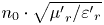 [Reference Hansen and Burke2, Reference Karilainen, Ikonen, Simovski and Tretyakov3, Reference Bae, Hong and Lyle6, Reference Nour and Breinbjerg10]. MDAs can be made frequency- [Reference Yang, Xing, Daigle, Liu, Obi, Stoute, Naishadham and Sun7] and polarization-agile [Reference Andreou, Zervos, Alexandridis and Fikioris1], the latter referring to switching between linear and circular polarization. Studies on MDAs also focus on the correct modeling of the dispersive and anisotropic magnetic properties [Reference Andreou, Zervos, Alexandridis and Fikioris1]. Hereinafter, the term MDA refers to antennas containing natural ferro-/ferri-magnetic inclusions in the substrate or elsewhere and not to antennas loaded by artificial metalo-dielectric structures.
Size and BW are certainly critical antenna attributes, but so are far-field properties. Since directivity is directly related to the physical antenna aperture, often the only way to increase the antenna gain is to improve its efficiency, ηrad, especially in compact antennas. Studies reporting numerical and/or measured data on MDA efficiency are generally limited [Reference Ikonen, Rozanov, Osipov, Alitalo and Tretyakov5–Reference Al-Sehemi, Al-Ghamdi, Dishovsky, Atanasov and Atanasova17]. These studies provide certain hints w.r.t. the effect of magnetic losses on efficiency; when magnetic properties are reasonably low in loss and dispersion (tanδμ ≤0.02) [Reference Ikonen, Rozanov, Osipov, Alitalo and Tretyakov5, Reference Bae, Hong and Lyle6, Reference Karilainen, Ikonen, Simovski, Tretyakov, Lagarkov, Maklakov, Rozanov and Starostenko9, Reference Nour and Breinbjerg10], then 50–80% efficient antennas are feasible; however, when magnetic losses dominate, as in [Reference Ikonen, Rozanov, Osipov, Alitalo and Tretyakov5, Reference Bae, Hong and Lyle6, Reference Nour and Breinbjerg10, Reference Aldrigo, Costanzo, Masotti, Baldisserri, Dumitru and Galassi11, Reference Al-Sehemi, Al-Ghamdi, Dishovsky, Atanasov and Atanasova17], efficiency can drop well below 10%.
Advances in MDA technology can occur through additive manufacturing, as recent developments in both manufacturing and materials engineering have opened up new possibilities. To the best of our knowledge, the first study on 3D-printable composite MD materials was [Reference Wang, Castles and Grant18], where NiZn spinel ferrite powder was dispersed in acrylonitrile butadiene styrene (ABS). In the 0.04–2 GHz range, measured material properties were $1.3 \le {\mu }^{\prime}_r \le 2$ and 0.1 ≤ tanδμ ≤ 0.3. Probably the first antenna to exploit a 3D-printable MD filament was presented in [Reference Parsons, Larimore, Lu and Mirotznik14]. Ferrimagnetic NiZn particles were mixed with a resin system and the macroscopic result was ${\mu }^{\prime}_r = 2.5$
 and tanδμ = 0.2 at 0.5 GHz. The most recent studies on 3D-printable composite MD materials aimed at implementing microwave absorbers rather than antennas [Reference Arbaoui, Agaciak, Chevalier, Laur, Maalouf, Ville, Roquefort, Aubry and Queffelec19, Reference Badin, Kuleshov, Zhuravlev, Dunaevskii, Simonova, Dorozhkin and Zhakupov20]. Arbaoui et al. [Reference Arbaoui, Agaciak, Chevalier, Laur, Maalouf, Ville, Roquefort, Aubry and Queffelec19] dispersed NiFe alloy particles in a polyethylene matrix. The result was $1.8 \le {\mu }^{\prime}_r \le 2.7$
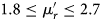 and tanδμ ≥ 0.25 at 0.5 GHz. Badin et al. [Reference Badin, Kuleshov, Zhuravlev, Dunaevskii, Simonova, Dorozhkin and Zhakupov20] dispersed M-type hexaferrite particles in ABS and studied microwave absorption at 46.5 GHz. At such high frequencies, it is hardly possible to obtain ${\mu }^{\prime}_r \gt 1$
 , but one can obtain a high magnetic loss (0.1 ≤ tanδμ ≤ 0.25).
This paper focuses on MDA fabrication and efficiency at 0.4–0.8 GHz. Our test antennas come from the novel class of MD microstrip patches in [Reference Sorocki, Piekarz, Slomian, Gruszczynski and Wincza21], whose substrate consists of a ferromagnetic filler dispersed in a polylactic acid (PLA) host matrix. The iron-doped PLA filament is a commercial-off-the-shelf (COTS) product [22]. Iron exhibits a remanence in the range Br = 0.25–1.3 T hence does not require a permanent external magnetic bias, which can be a challenge when building ferrite-based MDAs [Reference Andreou, Zervos, Alexandridis and Fikioris1, Reference Kakoyiannis, Zervos, Fikioris and Pissas12, Reference Varouti, Rongas, Manios, Kakoyiannis, Zervos, Pissas and Fikioris13, Reference Andreou, Alexandridis and Fikioris16]. Overall, if a 3D printer is available, the concept in [Reference Sorocki, Piekarz, Slomian, Gruszczynski and Wincza21] is the cheapest, fastest, and simplest way to build an actual MDA. Moreover, microstrip antennas are cavities radiating from two thin slots and are thus fully exposed to MD losses; an excellent test vehicle for ηrad investigations.
Section “Iron-doped additively manufactured magneto-dielectric microstrip antennas” describes the additive manufacturing of five increasingly thicker MDAs, which serve as test subjects for the study. In section “Wideband MDA efficiency measurements”, wideband efficiency measurements are performed on the five MDAs by way of the Wheeler cap technique. The measurements revealed an irregular dependence of ηrad on substrate thickness, H. Under the basic assumption that host material properties remain stable, the numerical analysis in section “Numerical reverse-calculation of magneto-dielectric material properties” calculates the apparent magnetic properties of the iron-doped substrates and finds a threefold decrease in loss tangent, tanδμ, whereas ${\mu }^{\prime}_r$ remains relatively constant. The dielectric counterparts of the five MDAs are also analyzed and compared as a reference. Lastly, simple optimization guidelines for MDA efficiency and gain are provided, to assess how far antenna performance can be pushed with the test material. The discussion in section “Discussion on the magnetic losses” will appeal to engineers actively engaged in magnetic materials; it identifies probable and improbable causes of the oddly decreasing tanδμ in an effort to encourage further research on low-loss, 3D-printer–compatible, composite MD materials. Section “Conclusion” concludes the paper.
Iron-doped additively manufactured magneto-dielectric microstrip antennas
When the substrate of a microstrip antenna is permeable (e.g. a host material mixed with a ferrimagnetic oxide), then ${\mu }^{\prime}_r \gt 1$ . To facilitate the investigation of additively manufactured MDAs, a set of patch antennas was realized exploiting the concept first proposed in [Reference Sorocki, Piekarz, Slomian, Gruszczynski and Wincza21]. Five edge-fed microstrip antennas operating at a center frequency of 0.6 GHz were manufactured. The selection of operating frequency is explained in detail later on. The antennas feature the same patch size, 100 mm × 100 mm, and the same ground plane size, 120 mm × 120 mm, however, differ in substrate height (thickness). Nominal values of targeted thickness H 1, …, H 5 were selected equal to 1.5, 2.0, 2.5, 3.0, and 4.5 mm, respectively. When electrical thickness exceeds 5%, the substrate is considered thick and surface waves become more pronounced; more on this in section “Numerical reverse-calculation of magneto-dielectric material properties”. The resonant length of an MD patch antenna is often approximated as $L\cong 0.49\cdot \lambda _0/\sqrt {{{\varepsilon }^{\prime}}_r{{\mu }^{\prime}}_r}$
 , where λ 0 is the free-space wavelength at resonance. Substrate size was dictated by the maximum test subject size that can fit into the efficiency measurement equipment.
The substrates were 3D printed using fused filament fabrication (FFF) technology out of the commercially available iron-enhanced PLA material. It is worth underlining that the above fabrication method is among the most established and cost-effective on the market, while still providing suitable resolution. Moreover, every piece is printed out of a solid, threadlike filament, whose preparation enables the inclusion of different kinds of dopants to the base polymer. The BM3D-175-MAG 1.75 mm low-cost filament by BlackMagic 3D [22] was used, which exhibits ${\varepsilon }^{\prime}_r, \;{\mu }^{\prime}_r \gt 1$ (${\varepsilon }^{\prime}_r{\mu }^{\prime}_r\approx 5.6$
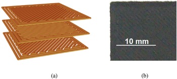
 at sub-GHz [Reference Sorocki, Piekarz, Slomian, Gruszczynski and Wincza21]), thus being well-suited for this study. For fabrication, a mid-range Original Prusa i3 MK3 3D printer by Prusa Research was used. Because of the iron content, the material is more abrasive and brittle than a standard PLA and thus requires greater attention. To avoid clogging and excessive wear, a 0.6 mm hardened steel nozzle by E3D was used. The digital 3D model of each substrate was sliced in the PrusaSlicer software at 0.25 mm layer height with 6/8/10/12/18 layers to produce G-code files (instruction set in geometric code language for computer numerical control machines, here the 3D printer) for substrates of the targeted thickness. The advantage of such a combination (wider nozzle diameter, thinner layer height) is a reduction in air voids [Reference Kuznetsov, Solonin, Urzhumtsev, Schilling and Tavitov23], which not only increases part strength, but more importantly increases substrate filling with MD material. In addition, a solid, 100% rectilinear-at-45° infill was used for all layers (including bottom and top) with an infill extrusion width of 0.45 mm for maximum printed trace density. Note that such a setting generates a printing path in which the print direction is interchanged for each layer and the consecutive layer lines are perpendicular to one another (see Fig. 1a). Manufacturing of the substrates was carried out at the extrusion temperature of Text = 215 °C (a temperature much lower than the Curie temperature of Fe, thus preserving ferromagnetism), heated bed temperature of Tbed = 60 °C, and cooling of 100% after the first layer. An example of a 3D-printed substrate is shown in the photograph of Fig. 1b.
(a) General view of the 100% rectilinear printing path and inter-layer trace geometry used, (b) close-up on the top layer of the printed MD substrate.

The substrates manufactured in the context of this study are fairly simple objects from the three-dimensional perspective, i.e. 120 mm × 120 mm × H 1…5 cuboids. They were printed line by line in the xy-plane and layer by layer in the z-axis. In FFF technology, the thermoplastic filament is fed from a large coil through a moving, heated extruder head, and is deposited on the growing work. Assuming a uniform distribution of iron dopants in the PLA filament, a quasi-uniform distribution of dopants in the substrate is expected (depending on how well the consecutive material lines are fused together) and the amount of iron is assumed to increase linearly with the substrate thickness. Unfortunately, no data are available on the exact procedure of filament preparation, as well as on the shape, size, and percentage content of iron dopants.
After manufacturing, the actual substrate thicknesses were measured with a caliper at eight locations per antenna and the corresponding spread of values is tabulated in Table 1. The five thickness ranges are isolated sets of values, a property that is crucial in what follows. The thickness designator for every antenna sample is written in bold typeface in Table 1.
Measured thickness of 3D-printed MD substrates

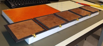
After 3D-printing of substrates, the top and bottom metal layers were fabricated in the same fashion as established in [Reference Sorocki, Piekarz, Slomian, Gruszczynski and Wincza21]. Square patches along with an 8 mm-wide feeding line (whose width was empirically determined) were cut out of 25 μm-thick copper tape with adhesive backing and were attached on top of the substrate; the ground plane was realized similarly on the bottom side. Skin depth in copper at 0.6 GHz is roughly 3 μm, which means that tape thickness is over eight times the skin depth; this is more than enough to keep Joule losses in check. The feed line impedance varies between antennas due to fixed width in the range of 25–50 Ω, however its 10 mm length corresponds to roughly 15° of electrical length at f 0; hence, the feed line is a lumped element and poses no issue from the perspective of efficiency measurement. Finally, sub-miniature type A (SMA) connectors were soldered at the open ends of the feed lines to enable measurements. A photograph of the manufactured MDA set is shown in Fig. 2.
Five 3D-printed microstrip MDAs arranged in order of increasing thickness from left to right.

Wideband MDA efficiency measurements
The efficiency of the five MDAs was measured by means of the Wheeler cap [Reference Kakoyiannis24–Reference Kakoyiannis26], a repeatable and accurate differential method that calculates efficiency indirectly by comparing two different states of the antenna under test (AUT): (a) radiating in free space, and (b) placed inside a Faraday shield to choke radiation. More information on this method can be found in the Appendix.
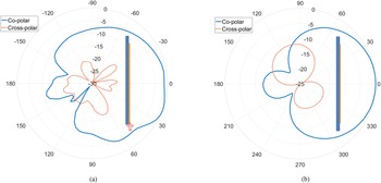
The 60 mm square patches in [Reference Sorocki, Piekarz, Slomian, Gruszczynski and Wincza21] operated at 1 GHz. On the basis of those measurements, it was estimated that a 100 mm square patch would operate at 0.6 GHz. The measured data in Fig. 3 indicate that 0.612 ≤ f 0 ≤ 0.638 GHz, where f 0 is defined herein as f 0 = argmin{|S 11|}. Importantly, the antenna impedance (mis)match poses no difficulty on the efficiency measurement, since all AUTs are accepting enough power in the 0.45–0.8 GHz band; it is time to determine if they can radiate that power. For completeness, the normalized radiation pattern of AUT #5 was also measured and is provided in Fig. 4; pattern shape and beamwidth are as expected for a standard microstrip patch antenna backed by a small ground plane.
Magnitude of free-space measured reflection coefficient at the input to each of the five prototype MDAs.

Measured radiation pattern of AUT #5 at the center frequency of 638 MHz at two principle cut-planes: (a) E-plane and (b) H-plane.

A cylindrical Wheeler cap was used during the shielded measurements; it is a variable-geometry cavity, whose top base moves along the vertical axis by means of special metallic fingers. The AUTs were mounted horizontally in the cavity with the direction of maximum radiation looking upwards. The inner diameter of the cavity is 180 mm; therefore, PCB size was limited to 120 mm. Maximum achievable inner height is 214 mm; the cavity height was fixed at a distance of one radianlength at 0.4 GHz (λ/2π = 120 mm) from the top surface of the AUTs, to avoid crushing the near-field of the AUTs and also to suppress in-band cavity resonances. The inner surfaces of the cavity are silver-plated at a thickness several times the skin depth.
The raw S-parameter measurements of the free-space and capped states of the antenna tell very little about ηrad; a post-processing of raw data is in order [Reference Kakoyiannis24–Reference Kakoyiannis26]. Two fundamentally different post-processors were applied in this study. The first one compares the measured Q-factors in the two states [Reference Kakoyiannis24]; quality factors were determined according to [Reference Yaghjian27]. This post-processor is known to be optimistic, i.e. it tends to overestimate efficiency. The reason is that antennas tend to store more energy in their near fields when mounted inside the cap. The second post-processor is a modified version of the frequency-swept variant of the improved Wheeler cap (IWC) [Reference Kakoyiannis25, Reference Kakoyiannis26]. After years of experience with the IWC, we have empirically concluded that it is a slightly pessimistic post-processor, i.e. it tends to underestimate efficiency. Further details on the two post-processors can be found in [Reference Kakoyiannis24–Reference Kakoyiannis26] and the pioneering references therein. A common property of modern Wheeler cap post-processors is that the AUT is required to be neither matched, nor tuned in the band of interest. This is the very foundation of broadband ηrad measurements. Not only is the modern Wheeler cap indifferent toward AUT impedance, it can also detect very small ηrad levels [Reference Kakoyiannis26].
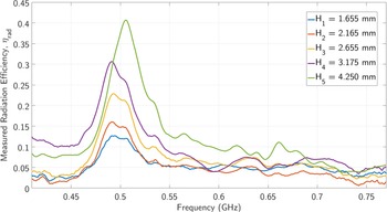
The Q-factor method [Reference Kakoyiannis24, Reference Yaghjian27] yielded the results shown in Fig. 5. In turn, the modified IWC [Reference Kakoyiannis25] estimated the efficiency levels depicted in Fig. 6. Both reveal the same trend in the response of the five MDAs: (a) efficiency in the vicinity of 0.6 GHz is rather low (5–12%), and (b) efficiency increases rapidly with substrate height in the 0.45–0.55 GHz band; the peak values of efficiency are listed in Table 2. It is worth noting that, despite the equipment restrictions on maximum physical size of the AUTs, and hence their resonant frequency, the region of increased efficiency was discovered thanks to the broadband measurement and post-processing.
Measured ηrad according to the Q-factor method [Reference Kakoyiannis24].

Measured ηrad according to the modified IWC [Reference Kakoyiannis25].

Measured and numerical results from the five, prototype, 3D-printed MDAs

These results can be compared to similar test cases from the recent literature. The patch antenna in [Reference Yang, Xing, Daigle, Liu, Obi, Stoute, Naishadham and Sun7] was loaded by a superstrate comprising 1–3 layers of very thin, self-biased magnetic films. Measured efficiency at 2.1 GHz monotonically increased from 41% (no superstrate) to 74% (3 layers); the mechanism behind this improvement was not explained in [Reference Yang, Xing, Daigle, Liu, Obi, Stoute, Naishadham and Sun7]. On the other hand, the patch antenna in [Reference Grange, Garello, Benevent, Bories, Viala, Delaveaud and Mahdjoubi8] was loaded by a self-biased, multilayer ferro-/antiferro-magnetic material that was inserted in the substrate. The reported measured efficiency was 34% at 2.08 GHz. Moving on to a different paradigm, an 8 mm-wide cylindrical yttrium-iron-garnet (YIG) ferrite was inserted in the substrate of the circularly polarized patch antenna in [Reference Kakoyiannis, Zervos, Fikioris and Pissas12]. This ceramic MD material required an external magnetic bias. With a saturated ferrite, the antenna exhibited dual-band response. In the original 5.6 GHz band, measured efficiency was 66%; in the lower 4.6 GHz band that was excited by the change in ferritic properties, efficiency dropped to 16%. Finally, the microstrip antenna in [Reference Andreou, Alexandridis and Fikioris16] was loaded by a substrate comprising YIG particles dispersed in an Epoxy polymer matrix. This composite substrate also required an external magnetic bias. Two different YIG-Epoxy composites were tested and efficiency was measured at a few frequencies in the 4.8–5.7 GHz range. Reported efficiencies ranged between 18–34 and 19–41% for the two composite substrates.
As a first conclusion, the COTS ferromagnetic PLA filament [22] led to a narrow band region, centered at 0.5 GHz, in which efficiency monotonically increases from 12 to 40%, as the normalized substrate thickness, H/λ 0, goes from 0.003 to 0.007. This means that a 2.57× increase in H caused a 3.33× increase in ηrad. Note that standard microstrip antenna thicknesses range between (0.01–0.05)λ 0, a typical value being 0.02λ 0 [Reference Balanis28–Reference Jackson and Volakis31]. Thus, all five MDAs were electrically very thin. A 0.02λ 0 thickness at 0.5 GHz would demand H = 12 mm; however, the available SMA connectors only allow thicknesses up to 7 mm, whereas filament availability restricted us to maximum 4.3 mm.
Although this study does not consider the impedance matching of the five MDAs, an antenna metric should be mentioned that paints a broader picture of antenna performance; the radiation quality factor [Reference Karilainen, Ikonen, Simovski, Tretyakov, Lagarkov, Maklakov, Rozanov and Starostenko9], Qr = QA/ηrad. This is a normalized Q-factor, in the sense that AUT losses have been stripped away by dividing with ηrad. The lower the Qr, the more broadband and/or the more efficient the antenna is. The radiation quality factor does not explicitly account for electrical size; for fair and meaningful comparisons, the AUTs should exhibit comparable electrical sizes, e.g. the same physical size and the same frequency of interest. Therefore, the Qr is ideal to describe the evolution of the 3D-printed MDAs discussed herein. In Table 3, we first calculated the total Q-factors of the AUTs based on [Reference Yaghjian27] at the frequencies where ηrad is maximized. We then obtained the measured radiation Q-factor for each AUT and both post-processors. The Qr values indicate that increasing the substrate thickness by 2.57 times causes a monotonic (4.2–4.8) × drop in Qr; a non-trivial improvement, nonetheless.
Measured radiation quality factor of the five MDAs

Numerical reverse-calculation of magneto-dielectric material properties
Section “Wideband MDA efficiency measurements” showed how the efficiency of the MD AUTs increases with substrate thickness, which is a known fact in microstrip antennas [Reference Balanis28–Reference Jackson and Volakis31]. This section will demonstrate that the actual rate at which the increase occurs is unusual. We first draw the reader's attention to certain important results from microstrip antenna theory, and then we seek to reverse-calculate the magnetic properties of the MD substrate by applying [Reference Shimin32].
Useful elements of microstrip antenna theory
Radiation efficiency is all about accounting for power that is dissipated in various ways, one of them being the power that couples with free space and radiates away from the antenna. Antenna design aims to make this form of power dissipation the dominant one. Different forms of dissipated power can be described by their corresponding quality factors. The loaded Q-factor, QA, of a standard dielectric microstrip antenna can be written as in (1) [Reference Balanis28–Reference Jackson and Volakis31]:

where Qr, Qc, Qd, and Qsw are the quality factors of the fundamental TM010 radiating mode, the conductive losses, the dielectric losses, and the zero-cutoff TM0 surface-wave mode, respectively. Efficiency increases with substrate thickness in standard dielectric patch antennas, because Qc is a linear function of H [Reference Balanis28–Reference Jackson and Volakis31]:

where σ is the conductivity of the metallization and δs is the skin depth at frequency f. When H << 0.01λ 0, the patch is too close to its image and conductive losses dominate over all other dissipation factors. However, as H increases toward 0.01λ 0, Qc stops being the dominant dissipation factor. Another interesting point made by (1) is that dielectric losses are independent of H. All substrates made of a given material, thin and thick, cause the same amount of power to be dissipated in that material.
In the MDA case examined here, both substrate and ground plane are terminated 10 mm away from the edges of the patch, hence surface-wave propagation is not actually a loss. The power carried away by the TM0 mode travels radially away from under the patch and is diffracted at the edges of the substrate. In this way, it becomes a secondary source of radiation, which combines vectorially with the TM010 mode in the far-field. If the vector summation of the two modes is destructive, then efficiency will experience a drop (the far-field pattern is also distorted by TM0 diffraction, however, this distortion falls outside the scope of the paper). All in all, the 1/Qsw contribution can be omitted in the context of this study.
Of course, a new term 1/Qm must be added to account for magnetic losses, which occur in parallel to the dielectric ones due to the presence of the iron filler. Therefore, in the MDA case, equation (1) can be re-written as:

Equation (3) makes yet another interesting point; magneto-dielectric losses simply add together and produce a total combined loss. Highly efficient 3D-printed MDAs require both a low-loss host material and a low-loss magnetic filler; the two losses are equally weighted.
Reverse-calculation of apparent permeability by full-wave transient EM simulations
For each of the printed antenna substrates, the complex permeability was determined by employing the principles of the resonance method [Reference Shimin32] with an iterative electromagnetic (EM) simulation fit, assuming that the complex permittivity remains stable with substrate thickness. The results of electromagnetic simulations are only as good as the available information on material properties. Three materials are of concern here: copper, PLA, and the ferromagnetic filler. The copper tape was assigned a quite reasonable conductivity of σ = 30 MS/m. As far as the dielectric properties of PLA are concerned, we borrow from the results of recent material characterization in [Reference Felício, Fernandes and Costa33, Reference Boussatour, Cresson, Genestie, Joly and Lasri34]; both studies agree that, in the lower microwave regime, the real part of PLA permittivity varies as in ${\varepsilon }^{\prime}_r = 2.75 \pm 0.15$ , whereas the loss tangent is on the order of ${\rm tan}\delta _\varepsilon \approx 0.011\approx 10^{{-}2}$
 . The values used in the finite-difference time-domain (FDTD) solver [Reference Wien35] were as follows:

Interestingly, PLA exhibits just a fraction of the loss tangent of FR-4. Hence, from (3) we can already tell how heavily the non-trivial dielectric losses of the filament influenced the ηrad values presented in section “Wideband MDA efficiency measurements”.
Virtual counterparts of the five prototype MDAs of Fig. 2 were built into a full-wave transient solver [Reference Wien35]; one such example is shown in Fig. 7. For the sake of simplicity, the SMA connectors were omitted; the antennas were excited by so-called Quasi transverse electric magnetic (QTEM) ports, which automatically detect the cross-section of the feeding line (including material properties) and calculate the propagation characteristics by running a 2D eigenmode solver on-the-fly.
The model of the 4.25 mm-thick MD microstrip antenna that was built in the FDTD solver [Reference Wien35].

It is noted that certain differences exist between the virtual and the actual prototypes. For instance, the substrate has been modeled as a flat rectangular box with a thickness equal to the median values listed in Table 1, without local variations. In the same context, both dielectric and magnetic properties were assumed to be isotropic. PLA melts and re-solidifies during 3D printing, whereas the micromagnetic structure of the iron filler is completely unknown. Last but not least, the copper cladding of the five prototype antennas was effective, albeit rough-and-basic. The 8 mm-wide feeding lines were excited by soldering a coaxial SMA connector at their open end, as per Fig. 2. At the soldering point, there exists a 1 mm-wide gap, which is bridged by the center pin of the connector but still adds a small amount of distributed capacitance. Like the SMA connectors, this capacitance was not present in the EM simulations.
The results tabulated in Tables 2 and 3 already indicate that the 3D-printed MDA evolves into a better radiator as the substrate becomes thicker. We have no reason to believe that the properties of PLA change with the number of 3D-printed layers. The iron particles, on the other hand, have unknown shapes, sizes, and doping densities, and are also randomly dispersed in the host polymer matrix. Equally importantly, all five MDAs were printed from the same batch of ferromagnetic PLA [22]. Therefore, the purpose of the EM simulations is to investigate whether it is possible that the magnetic properties of the substrate change with the increasing number of deposited layers. In this context, we can only speak about the apparent magnetic permeability, i.e. the macroscopic result that is produced by a large number of permanently magnetized iron particles dispersed in the PLA host. The results of the EM simulations are given in Table 4, where w.r.t. the apparent relative permeability of the material, the notation $\mu _r = {\mu }^{\prime}_r( {1-j\ {\rm tan}\delta_\mu } )$ holds. Table 4 also provides the theoretical resonant frequency that depends upon antenna length and substrate properties only [Reference Balanis28]. Table 4 reveals two points of interest. First, the apparent ${\mu }^{\prime}_r$
 remains fairly stable at ${\mu }^{\prime}_r = 2.07 \pm 0.11$
 (±5%). A permeability on the order of 2 is a non-trivial magnetic property, which the antenna engineer can effectively use in, e.g. antenna miniaturization. Second, the increasing ηrad of the five MDAs was not due to the sheer effect of H on Qc; rather, the increasing H brought about a sharp drop in the apparent tanδμ. The tanδμ values for every H stem from the two ηrad values in Table 2. Given the stable values of ${\mu }^{\prime}_r$
 , this is a sharp drop in ${\mu }^{\prime \prime}_r = {\rm Im}\{ {\mu_r} \}$
 ; for reasons discussed in section “Discussion on the magnetic losses”, the magnetic component of the MD material dissipates smaller amounts of power as the substrate gets thicker. Note that the thickest substrate (H 5 = 4.25 mm) already exhibits an apparent combined loss tangent of 0.018 ± 0.004, which is reminiscent of standard FR-4.
Reverse-calculated permeability and aggregate losses of the five MD substrates (at tanδε = 0.011)

Magnetic material properties are usually anisotropic, in which case μr is no longer a scalar, but rather takes the form of a tensor [Reference Andreou, Zervos, Alexandridis and Fikioris1]. With reference to the coordinate system shown in Fig. 7, the calculated μr-values in Table 4 correspond to the first diagonal element of the tensor, i.e. ${\mu }^{\prime}_r \triangleq {\mu }^{\prime}_{xx}$ . The values of ${\mu }^{\prime}_{yy}$
 and ${\mu }^{\prime}_{zz}$
 have practically no effect on the electrical response of the microstrip antenna, so there is no simple way of telling whether they exceed unity or not.
Numerical analysis of the equivalent dielectric microstrip antennas
So far, we verified that a 3D-printed MDA can be improved by having its substrate thickened. This section will draw comparisons with the reference microstrip antenna, i.e. the equivalent radiator with no magnetic component. This is a patch antenna with identical geometry and physical dimensions but with an adjusted real part of permittivity, ${\varepsilon }^{\prime}_r$ , that leads to the same f 0. The next question is, what sort of losses would make for a fair comparison. An initial thought was to set the losses of this equivalent substrate to ${\rm tan}\delta _\varepsilon + {\rm tan}\delta _\mu$
 as per Table 4, but this is superficial: commercial polytetrafluoroethylene (PTFE)-ceramic substrates (either glass-reinforced or not) with ${\varepsilon }^{\prime}_r\approx 6$
 exhibit loss tangents as low as 0.002. At the other end of the market spectrum, there are several FR-4 products with losses on the order of 0.020. Therefore, it was decided that an average loss value of ${\rm tan}\delta _\varepsilon = 0.011$
 should be assigned to the equivalent substrate, which is the same as pure PLA.
The only geometrical adjustment allowed in this EM model was setting the feeding line width for 50 Ω; see the values of W 50 in Table 4. This table also provides the effective permittivity, effective length, and resonant frequency, which were calculated from the antenna transmission-line model [Reference Balanis28]; these explain the variation in center frequency of the fabricated samples. The patch antenna was again edge-fed since an inset feed would improve the matching and hence affect the Q-factor.
The results that pertain to peak efficiency, loaded Q-factor, and radiation Q-factor of the reference microstrip antennas are listed in Table 5. As a quick comment, the Q-factors of the reference antenna stay in the range 48–66, whereas those of the MDAs varied as in 9–14. This makes the radiation Q-factors of the reference antennas skyrocket as high as 400.
Properties of the dielectric reference antennas

Table 4 silently implies that the benefits of magnetic loading are subject to proper application. The MDAs studied herein are sub-optimally loaded, since the MD material is omnipresent in the substrate. A microstrip antenna is optimally loaded when the MD material covers only the volume under the two flanks of the patch, where the non-radiating H-field is locally maximized. This means that 3D-printed MDAs have the potential to perform even better than what is indicated by Tables 2 and 3.
Figure 8 depicts the higher rate of increase of ηrad as a function of H w.r.t. the reference antenna, owing to the monotonically decreasing apparent ${\rm tan}\delta _\mu$ of the MD substrate. The results of the reference antenna are, of course, a function of ${\rm tan}\delta _\varepsilon = 0.011$
 . Had the antennas been compared on an equal-loss basis, the reference curve would be shifted 10 percentage points lower.
A comparison of the rates at which efficiency increases with thicker substrates.

Getting the most out of a 3D-printed MDA
With reference to Figs 2 and 7, there are three basic attributes of the antenna that can be improved in order to squeeze the maximum possible performance out of a simple MD patch antenna. The first one was briefly mentioned in section “Numerical analysis of the equivalent dielectric microstrip antennas” and has been studied elsewhere [Reference Karilainen, Ikonen, Simovski and Tretyakov3, Reference Grange, Garello, Benevent, Bories, Viala, Delaveaud and Mahdjoubi8, Reference Karilainen, Ikonen, Simovski, Tretyakov, Lagarkov, Maklakov, Rozanov and Starostenko9, Reference Rongas, Kakoyiannis and Fikioris15]: optimal magnetic loading. It provides the size and BW that the designer needs at the maximum possible efficiency, i.e. it optimizes the QA−ηrad trade-off and minimizes Qr. The second is the adjustment of the aspect ratio of the patch, W/L, to some desired value (usually 1 ≤ W/L < 2) that provides the required BW and also the required beamwidths in the θ- and φ-planes. The third attribute, whose effect is briefly studied here, is the extent of the ground plane. Indeed, the size of the reflector backing the patch can be adjusted to maximize the efficiency and/or directivity, and finally gain. The basic gain equation written in decibel notation, G max,dB = η rad,dB + D 0,dB, tells us that the two factors are equally weighted and contribute decibel-for-decibel to antenna gain.
With 3D-printing technology, the MD material can either remain fixed in size, or it can follow the size of the ground plane. For the sake of brevity, only the first option is studied here (see Fig. 9): the side length of the ground (GND) plane, Wgnd, was increased to 190 mm while keeping the sizes of patch and MD substrate constant. This last numerical study is an independent, broader discussion, so the microstrip line was allowed to enter the patch by 28 mm to find the 50 Ω feeding point. We used the EM model of the 4.25 mm-thick MDA. The side length of the (square) GND plane was increased from the initial value of 120 to 500 mm; far-field characteristics were recorded every step of the way; once again, impedance matching is irrelevant (but it did remain below −10 dB at the frequency of interest, f 0 = 0.638 GHz). The permeability of the MD substrate was set to μ r = 2.03(1 − j 0.007), hence the aggregate magneto-dielectric losses of the material were ${\rm tan}\delta _\varepsilon + {\rm tan}\delta _\mu = 0.018$ .
Inset-fed MDA with Wgnd = 190 mm. Patch and substrate sizes remain fixed at 100 and 120 mm, respectively.

The vector summation of the diffracted TM0 mode with the radiated TM010 mode in the far-field changes as a function of ground size. In this scenario, the substrate is always terminated 10 mm away from the patch, hence TM0 mostly forms a standing wave inside the material, due to the difference in refractive index. However, a small part of the power is refracted at the boundary between Fe-PLA and air and, thus, ground currents reach the edges of the ground plane, where they are diffracted. Figure 10 shows that this diffraction combines optimally with the radiated mode when Wgnd = 170 mm; at that design point, efficiency reaches a maximum of ηrad = 49.4% (−3.1 dB). This is a 1.2 dB improvement w.r.t. Table 2.
Changes in radiated efficiency of the virtual MDA as a function of GND size (only GND changes size).

On the other hand, Fig. 11 shows that the maximum directivity increases monotonically with the ground size until it reaches the plateau of very large grounds at Wgnd = 350 mm; at that point, maximum directivity settles at roughly +7 dBi. This behavior is typical of microstrip antennas; see Table 6-1 in Milligan [Reference Milligan30]. The combined effect of ηrad and D 0 maximizes the antenna gain at Wgnd = 190–195 mm, where Gmax = + 2.8 dBi instead of the initial +0 dBi value. This is the optimal design point for this version of the MDA and it makes no sense to make the reflector bigger (unless, of course, one wishes to obtain a front-to-back ratio higher than the offered 9 dB).
Changes in maximum directivity and maximum gain of the MDA as a function of GND size (only GND changes size).

Discussion on the magnetic losses
An attempt is made to identify probable and improbable causes for the reduction of the apparent tanδμ as more Fe-PLA layers are successively 3D-printed. For the micro-magnetic properties of the iron filler that remain unknown, reasonable assumptions will be made to facilitate this discussion. For example, could the iron particles be single-domain? This is the state of a ferromagnet in which the magnetization, M, is constant across the magnet [Reference Goldman36]. Single-domain particles are generally below 1 μm in diameter. It is unlikely that a cheap 3D-printing product includes a nano-scale filler; particle diameters are expected to be in the 10–100 μm range. Hence, the filler is multiple-domain, so there exist domain walls that can dissipate radio-frequency (RF) power by shifting.
The iron particles dispersed in the PLA host matrix [22] are a form of powdered metal. Therefore, an analogy can be drawn with powder cores that are used in low-frequency/high-frequency (LF/HF) transformers and telecommunications [Reference Goldman36]: the substrate consists of metal grains (iron) mixed with a suitable organic binder (PLA). The RF losses of powdered iron exposed to the EM field inside the cavity of a microstrip antenna can be divided in four categories: (a) hysteresis, (b) domain-wall, (c) eddy-current, and (d) Joule losses. Each of the four mechanisms is examined as a possible contributor to the decreasing ${\rm tan}\delta _\mu$ .
Hysteresis loss is directly related to the area under the hysteresis (B-H) curve, which describes how fast the magnetic flux through the ferromagnet changes under the influence of an external magnetic field. To the best of our knowledge, this property cannot be altered by the 3D-printing process. More importantly, hysteresis losses are dominant in ferromagnets only at frequencies up to a few megahertz [Reference Liu, Wu, Wang, Qiao, Wang and Li37].
The time-variant H-field flowing through the iron grains causes a change in M by the expansion and contraction of the tiny magnetic domains, which is manifested as a shifting of the domain walls. This process causes RF losses because the domain walls get stuck on defects in the crystal lattice and then break away past them, dissipating power as heat. This is known as domain-wall loss and it is the principal contributor to what is called excess loss [Reference Liu, Wu, Wang, Qiao, Wang and Li37]; often the two are considered identical. The printing of progressively more layers of iron-doped PLA exposes the iron grains for a longer period to temperatures as high as 220–230 °C inside the molten PLA. We consider it unlikely that this thermal treatment can change the crystal properties of iron in a direction that would reduce losses, i.e. remove lattice defects and/or reduce the number of magnetic domains in the grains.
Since iron is electrically conductive, the time-variant H-field induces circulating loops of current in the particles due to Faraday's law of induction, called eddy currents. The loops flow perpendicular to the magnetic field axis and their power is dissipated as heat. The power loss is proportional to the area of those loops. Finer particles allow operation at higher frequencies, as the eddy currents are mostly restricted inside the individual grains [Reference Grange, Garello, Benevent, Bories, Viala, Delaveaud and Mahdjoubi8, Reference Goldman36]. Coating of the iron particles with an insulating layer, e.g. as in carbonyl iron powder [Reference Goldman36, Reference Liu, Wu, Wang, Qiao, Wang and Li37], lowers the eddy current losses for the same reason; in our case, this is a task for the PLA binder. With reference to the coordinate system shown in Fig. 7, the H-field in the antenna cavity is x-oriented, therefore eddy currents become a problem when large iron areas exist parallel to the yz plane. Eddy current loss can be suppressed in two ways: (a) by separating agglomerate particles and thus reducing the effective area of the eddy loops, and (b) by distributing the particles flat in the xy- and xz-planes, not allowing any metal surface perpendicular to the H-field.
It is unknown whether the iron particles are of cubic, spherical, or ellipsoidal shape. Assuming they are needle-like ellipsoidal, then Joule losses can become a part of the total RF loss. Inside the cavity of the antenna, under the patch, a very strong vertical E-field exists. The alternating RF voltage produces currents in the grains unless they are completely flat and horizontal. The finite conductivity of iron causes power dissipation in the form of Joule losses. It is possible that some mechanism, e.g. thermal motion or magnetic forces, makes the particles align horizontally in the cavity, rather than vertically. It has been shown, however, that ferromagnetic particles with very large aspect ratios are in fact desired, since they can exhibit lower domain-wall and lower eddy-current losses [Reference Liu, Wu, Wang, Qiao, Wang and Li37].
The dispersion of iron grains inside the binder creates air pockets, i.e. distributed air gaps. The 3D-printing process itself contributes its own air pockets. The thickness variation, i.e. layer extrusion variation of the final product, is on the order of tens of microns; see Table 1. Therefore, it could be argued that increasing thickness increases the porosity of the substrate: the more porous the composite substrate is, the less amount of iron filler, hence the lower the iron losses. However, Table 4 suggests otherwise: if increasing porosity were an actual problem, then the values of apparent $\mu _r^{\prime}$ would not remain stable within ±5%. Besides, we can only assume that the 3D-printed filament is consistent and uniform in terms of iron volume distribution. The same holds for the air pockets that form in the MD substrate during 3D-printing, thus an identical porosity should be expected across all thicknesses. In other words, the air volume per unit thickness is roughly constant, since it is affected by 3D-printing parameters, such as printed extrusion path, temperature settings, etc. A nice discussion on how to avoid air pockets when using FFF 3D-printing is given in [Reference Hanemann, Syperek and Nötzel38].
The most plausible explanation for the reduction in $\tan \delta _\mu$ seems to be the reduction in eddy current loss. Since the material is extruded under high temperature, there is a time required to cool down and solidify. As the layers build up, each new layer is exposed to the aggregate H-field of the layers below. A combination of magnetic forces and thermal motion could suffice to make the iron dopants rotate and drift apart, i.e. to not allow particles to accumulate. In this way, iron grains would become electrically isolated and form tiny magnetic circuits. This would reduce eddy current loss through a reduction in the current loop area. The reduction in apparent $\tan \delta _\mu$
 is beyond threefold, which suggests that eddy currents are the dominant loss mechanism in the five MDAs.
Conclusion
A COTS PLA filament doped with iron particles of unknown micromagnetic properties [22] was innovatively applied to study 3D-printed microstrip MDAs in a one-octave BW (0.4–0.8 GHz). This practically random MD material enabled the quick-and-dirty fabrication of five microstrip MDAs. They yielded efficiency levels monotonically increasing up to 40% at 0.5 GHz, as the normalized substrate thickness, H/λ 0, increased from 0.003 to 0.007, even though the material itself is relatively lossy. Radiation quality factors decreased also monotonically from 110 down to 23. A shortage of PLA filament restricted us to a maximum thickness of 4.3 mm, hence we could not demonstrate this continuing trend for thicknesses H/λ 0 ≥ 0.01.
Although the increase in microstrip antenna efficiency with substrate thickness is no news, it was shown that the rate of increasing ηrad can become substantially higher than the corresponding dielectric antenna. This higher ∂ηrad/∂H rate was the symptom of the rapidly decreasing apparent magnetic loss; a 2.57× increase in H caused a more-than-threefold drop in apparent ${\rm tan}\delta _\mu$ from 0.023 ± 0.001 to 0.007 ± 0.004.
Despite the sub-optimal magnetic loading, the MDAs proved to be significantly better radiators than their dielectric counterparts, whose radiation Q-factors were 3.7–7.2 times higher. Furthermore, by optimizing the dimensions of the GND plane, the 4.25 mm-thick, sub-optimally-loaded MDA showed potential for an efficiency of 50–55%.
As far as the oddly decreasing ${\rm tan}\delta _\mu$ is concerned, four probable causes were qualitatively examined: a reduction in the losses induced by hysteresis/domain walls/eddy currents/Joule phenomena and an increase in substrate porosity. The most plausible explanation that can be offered at this point is a reduction in eddy current loss through a reduction in the current loop area. This could result from the extended thermal treatment and the aggregate magnetic field of the underlying layers, which could force the iron particles to separate and become electrically isolated.
The future of 3D-printable MD substrates seems both promising and exciting. Firstly, the use of an external magnetic bias close to the FFF nozzle can magnify the magnetic properties [Reference Hanemann, Syperek and Nötzel38]; this is easily achieved with an electromagnet. Printable (in)organic hosts with substantially lower losses compared to PLA would also be a welcome development. More importantly, materials science has already started working on low-loss ferromagnetic fillers, albeit with a focus on power electronics [Reference Liu, Wu, Wang, Qiao, Wang and Li37]. Moreover, iron particles can be replaced by ceramic ferrite powder, which is an insulator and does not suffer from eddy currents or other Joule losses. Such research has already been set in motion [Reference Parsons, Larimore, Lu and Mirotznik14, Reference Wang, Castles and Grant18–Reference Badin, Kuleshov, Zhuravlev, Dunaevskii, Simonova, Dorozhkin and Zhakupov20, Reference Hanemann, Syperek and Nötzel38, Reference Wei, Liu, Zhao, Mao, Jiang and Ge39]. Rare-earth garnets and spinel ferrites require an external magnetic bias and, in any case, long-term sustainability of magnetodielectric antennas calls for a paradigm shift away from rare earths. NiZn spinels [Reference Parsons, Larimore, Lu and Mirotznik14, Reference Wang, Castles and Grant18] and M-type hexaferrites, especially barium- and strontium-based, are excellent candidates due to their abundant raw materials and pronounced magnetic properties [Reference Hanemann, Syperek and Nötzel38, Reference Wei, Liu, Zhao, Mao, Jiang and Ge39]. It is noted that ceramic ferrites come with high values of permittivity, in the range ${\varepsilon }^{\prime}_r = 8-20$ , which is detrimental to both BW and ηrad. The apparent permeability of the composite substrate need not be very high; values in the range $2 \le {\mu }^{\prime}_r \le 7$
 suffice for antenna design [Reference Rongas, Kakoyiannis and Fikioris15]. Therefore, mixing ratios should be adjusted so as to obtain the required ${\mu }^{\prime}_r$
 with low magnetic losses and low composite permittivity.
The combination of additive manufacturing (3D printing) with a low-cost MD filament proved to be a promising approach toward building microstrip antennas that are mechanically robust, lightweight, and extremely cost-effective. Additively manufactured magneto-dielectric devices can play a significant role in the miniaturization, BW enhancement, polarization reconfigurability, and frequency agility of future planar antennas.
Acknowledgements
This work was supported by the National Science Centre of Poland under Grant 2019/34/E/ST7/00342.
Conflict of interest
None.
Appendix: elements of the Wheeler cap method
The Wheeler cap [Reference Kakoyiannis24–Reference Kakoyiannis26] is a differential, near-field estimator of antenna efficiency. First, the impedance of the AUT is measured under free-space conditions, e.g. in an anechoic chamber. Then the antenna is measured a second time under shielded conditions, i.e. inside a cavity or cap. Figure 12 depicts the measurement of a patch antenna in a hemispherical shielded cavity. The distance from the edges of the antenna to the cavity walls should be λ/2π at the lowest frequency of interest, to avoid distortion of the near-field; the Wheeler concept is based on the fact that “the same antenna” should be measured in and out of the cavity. Nevertheless, distances as small as λ/20 can still preserve the accuracy of the method. When the AUT fires in the cap, its radiation resistance is shorted (zeroed-out), since the antenna cannot actually radiate. Assuming the AUT is at resonance, comparison of the capped input impedance with the free-space one gives two equations in two unknowns and allows us to separate the radiation resistance from the loss resistance. Efficiency is then calculated as in ηrad = Rrad/(Rrad + Rloss). It is noted that the advanced post-processors applied herein enable us to perform the separation in a wide bandwidth, because they alleviate the necessity of resonance.
A generic microstrip patch antenna placed inside a hemispherical Wheeler cap for the shielded part of the differential measurement.

 Constantine Kakoyiannis earned the Diploma in electrical and computer engineering and the Doctor of Engineering degree at the National Technical Uni. Athens (NTUA), Greece, in 2000 and 2011, respectively. From 2001 until 2011 he worked as a MW/RF antenna engineer at the Institute of Communications and Computer Systems, NTUA. In 2012–2015 he was a post-doctoral research fellow of NCSR “Demokritos”, Athens, Greece, working on reconfigurable magneto-dielectric antennas. Concurrently, he worked for CST AG, Darmstadt, Germany, providing technical support and training services. Since 2016 he has been an antenna R&D engineer with IMST GmbH, Kamp-Lintfort, Germany, where he develops novel antenna systems from VHF up to mm-waves. He has authored over 45 peer-reviewed papers, one book chapter, and holds one patent. His research interests include small antenna theory and design, antenna miniaturization, wideband efficiency measurements, phased arrays and feeding networks, mutual coupling suppression, magneto-dielectric antennas, and time-domain full-wave modeling. Dr. Kakoyiannis is a member of EuMA, EurAAP, and the IEEE.
 Jakub Sorocki received the M.Sc. and Ph.D. degrees in the field of electrical engineering from the AGH University of Science and Technology, Krakow, Poland in 2013 and 2018, respectively. Since 2012 he has been cooperating with the Microwave Technology and High-Frequency Electronics Research Group, Department of Electronics, AGH UST. In 2012, he was a visiting student at the Ilmenau University of Technology, Germany. In 2017, he was a visiting researcher at the Michigan State University, USA. In 2019, he was employed as a systems engineer for ADAS mm-wave radars in the automotive industry. In 2020/21, he was a visiting post-doctoral researcher at the University of Pavia, Italy. His research interests focus on the development of low-loss and high-performance microwave circuits in strip transmission line techniques employing subtractive and additive technologies. He has co-authored over 60 publications in peer-reviewed journals and conferences. Dr. Sorocki is a member of IEEE MTT-S and EuMA.
 Ilona Piekarz received the M.Sc. and Ph.D. degrees in the field of electrical engineering from the AGH University of Science and Technology, Krakow, Poland in 2013 and 2018, respectively. Since 2011 she has been cooperating with the Microwave Technology and High-Frequency Electronics Research Group, Department of Electronics, AGH UST. In 2012, she was a visiting student at the Ilmenau University of Technology, Germany. In 2017, she was a visiting researcher at the Michigan State University, USA. In 2019, she was employed as a systems engineer for ADAS mm-wave radars in the automotive industry. In 2020/21, she was a visiting post-doctoral researcher at the University of Pavia, Italy. Her research interests focus on the development of sensors and measurement systems in strip transmission line techniques for industrial and biomedical applications that take advantage of both subtractive and additive fabrication techniques. She has co-authored over 60 publications in peer-reviewed journals and conferences. Dr. Piekarz is a member of IEEE MTT-S and EuMA.
 Matthias Geissler was born in Tauberbischofsheim, Germany, in 1968. He received the M.Sc. degree in electrical engineering from the University of Karlsruhe, Germany, in 1995, and the Ph.D. degree from the University of Duisburg-Essen, Germany, in 2003. In 1995, he joined IMST GmbH, Kamp-Lintfort, Germany, where he was involved in design of planar antennas as well as antennas for mobile applications. He was involved in fundamental limitations and exact characterization of small antennas. In 2003, he became head of the Antennas and EM Modeling Department, IMST GmbH. Since 2006, he has been a lecturer with Ruhr-University Bochum (RUB), Germany. Since 2008, he is a vice president of IMST GmbH. In 2015, he became an honorary professor of the RUB. He has (co-)authored over 70 papers in conferences, scientific magazines, and books. He holds several patents. His current research interests include 3D EM modeling, multiband antennas for mobiles, MIMO, agile planar arrays for mobile communications, satellite communications, and radar applications.