



1 Introduction
When an interface between two different fluids is impulsively accelerated by a shock wave, the perturbations initially deposited on the interface will grow with time after a short period of contraction and finally develop into turbulent mixing. The phenomenon is often referred to as Richtmyer–Meshkov instability (RMI) (Richtmyer Reference Richtmyer1960; Meshkov Reference Meshkov1969), which has attracted increasing attention in recent decades because of its academic significance in vortex dynamics and compressive turbulence as well as important applications in the fields of inertial confinement fusion (Lindl et al. Reference Lindl, Landen, Edwards, Moses and Team2014), supersonic combustion (Yang, Kubota & Zukoski Reference Yang, Kubota and Zukoski1993) and supernova explosions (Arnett et al. Reference Arnett, Bahcall, Kirshner and Woosley1989). The previous progress on the RMI in experimental, numerical and theoretical aspects has been summarized in several comprehensive reviews (Zabusky Reference Zabusky1999; Brouillette Reference Brouillette2002; Ranjan, Oakley & Bonazza Reference Ranjan, Oakley and Bonazza2011; Luo et al. Reference Luo, Zhai, Si and Yang2014).
In study of the RMI, much attention has been paid to the generation of an initially perturbed interface with well-characterized perturbations because of its great influence on instability development. In pioneering work, a nitrocellulosic membrane was adopted by Meshkov (Reference Meshkov1969) to form a two-dimensional (2-D) discontinuous single-mode interface to validate the theoretical impulsive model (Richtmyer Reference Richtmyer1960). This interface formation method was also used in some other experiments (Prasad et al. Reference Prasad, Rasheed, Kumar and Sturtevant2000; Mariani et al. Reference Mariani, Vanderboomgaerde, Jourdan, Souffland and Houas2008), but it was found that the small remaining membrane pieces would be incorporated into the flow, impeding flow visualization and potentially affecting interface deformation. In order to eliminate the effect of the membrane, a membraneless single-mode interface was created by retracting a plate between two different gases (Brouillette & Sturtevant Reference Brouillette and Sturtevant1993; Bonazza & Sturtevant Reference Bonazza and Sturtevant1996). The limitations of these experiments came from the fact that the initial perturbations were uncontrollable, non-uniform and often unrepeatable. Later, another technique was proposed by Jones & Jacobs (Reference Jones and Jacobs1997) to generate a single-mode interface. Light and heavy gases were supplied from opposite sides of the shock tube driven section, and an initial perturbation with sinusoidal shape was generated by gently oscillating the shock tube at a prescribed frequency in the horizontal direction. A pin-restriction method based on the soap film technique was developed in our group to form polygonal gas interfaces, where thin pins were used as angular vertexes to connect the adjacent sides of soap films and pressure singularities around the vertexes caused by the surface tension were avoided (Wang, Si & Luo Reference Wang, Si and Luo2013; Zhai et al. Reference Zhai, Wang, Si and Luo2014a ; Luo et al. Reference Luo, Wang, Si and Zhai2015). Besides, much attention has been paid to three-dimensional (3-D) single-mode interfaces. Chapman & Jacobs (Reference Chapman and Jacobs2006) modified the apparatus of Niederhaus & Jacobs (Reference Niederhaus and Jacobs2003) to generate a 3-D single-mode perturbation between two incompressible and miscible liquids. The results indicated that the vorticity pattern was affected by 3-D effects and the 3-D amplitude was found to suffer from a much more significant nonlinear growth. Based on the shock tube facility of Jones & Jacobs (Reference Jones and Jacobs1997), modification was made by Long et al. (Reference Long, Krivets, Greenough and Jacobs2009) using opposed flows of two different gases to form a single-mode 3-D initial perturbation. Recently, a novel method was proposed by Luo, Wang & Si (Reference Luo, Wang and Si2013), Luo et al. (Reference Luo, Guan, Si, Zhai and Wang2016b ) using the soap film technique to generate a 3-D single-mode interface with a minimum-surface feature and the 3-D effects of the initial shape on the interface development were studied.
Among the initial interfaces previously reported, spherical and cylindrical configurations are fundamental ones as they cover the complete range of angles between the pressure and density gradients, which would affect the distribution of baroclinic vorticity deposited on the interface. Significant progress of spherical gaseous interfaces subjected to a shock wave has been reviewed by Ranjan et al. (Reference Ranjan, Oakley and Bonazza2011). Moreover, a number of experiments and simulations have also been performed to explore the dynamics of shock-accelerated cylindrical gas interfaces. In the very early work, Rudinger & Somers (Reference Rudinger and Somers1960) studied the behaviour of cylindrical gas bubbles in accelerated flows experimentally and theoretically, where the bubbles were created using a fine jet technique. The classical experimental work performed by Haas & Sturtevant (Reference Haas and Sturtevant1987) reported the wave patterns and the detailed evolution of cylindrical and spherical gaseous inhomogeneities. The discontinuous 2-D gas cylinder reported in their work was formed by means of a nitrocellulosic membrane and the cylinder development was inevitably influenced by the membrane fragments and the holder. As a result, the experiments exhibited a significant amount of small-scale three-dimensionality. Later, Picone & Boris (Reference Picone and Boris1988) numerically studied the early and late time phenomena of this classical experiment, and examined the vorticity generated by the shock–cylinder interaction. Quirk & Karni (Reference Quirk and Karni1996) also simulated these experiments and concentrated on the early stages of the shock–cylinder interaction. Differently, a membraneless light gas cylinder in the form of a round laminar jet was first realized by Jacobs (Reference Jacobs1992) in a horizontal shock tube to eliminate the influence of the membrane fracture. Afterwards, the jet technique was widely used in the RMI experiments to form various initial interfaces, including heavy gas cylinders (Tomkins et al. Reference Tomkins, Kumar, Orlicz and Prestridge2008; Zhai et al. Reference Zhai, Zhang, Si and Luo2014b ), multiple gas cylinders with different arrangements (Kumar et al. Reference Kumar, Orlicz, Tomkins, Goodenough, Prestridge, Vorobieff and Benjamin2005), gas curtains (Balakumar et al. Reference Balakumar, Orlicz, Ristorcelli, Balasubramanian, Prestridge and Tomkins2012; Balasubramanian et al. Reference Balasubramanian, Orlicz, Prestridge and Balakumar2012; Tomkins et al. Reference Tomkins, Balakumar, Orlicz, Prestridge and Ristorcelli2013) and single gas cylinders with an elliptic section (Zou et al. Reference Zou, Liu, Tan, Huang and Luo2010). In this method, three-dimensionality inevitably occurs due to the gas diffusion and axial density variation (Weirs, Dupont & Plewa Reference Weirs, Dupont and Plewa2008).
Despite the achievements, the experimental investigation of RMI remains a big challenge in laboratory conditions. It is desirable to further develop techniques for generating initial interfaces with specific shapes. It would be interesting to perform experiments that are able to systematically investigate the 3-D effects of the initial perturbations on the development of different gaseous inhomogeneities. Recently, Wang et al. (Reference Wang, Yang, Wu and Luo2015) introduced a circular wire-restriction method based on the soap film technique to form the 2-D gas cylinder. The formed interface is free of the holder and gas diffusion can be largely avoided. In the present study, the method is extended to form 2-D, 3-D concave and 3-D convex cylinders. The formed initial interfaces can be identified more clearly relative to the previous counterparts. By controlling the pressure inside the cylinders, the concave cylinder has a minimum-surface feature where the two principal curvatures at every point of the interface are the same in amplitude but opposite in direction, and the convex cylinder has identically signed principal curvatures along the interface. The interactions of a planar shock with the 3-D gas cylinders are investigated experimentally and numerically to highlight the three-dimensionality of RMI.
2 Experimental methods
The experiments are conducted in a horizontal shock tube consisting of a 1.7 m long driver section, a 2.0 m long driven section and a 0.6 m long test section with a rectangular cross-sectional area of
 $140~\text{mm}\times 20~\text{mm}$
. The small height (i.e. 20 mm) of the test section is adopted to minimize the gravity effect of the formed gas cylinder. This shock tube facility has been successfully employed to study the interaction of a planar shock with polygonal gas cylinders (Wang et al.
Reference Wang, Si and Luo2013; Zhai et al.
Reference Zhai, Wang, Si and Luo2014a
; Luo et al.
Reference Luo, Wang, Si and Zhai2015) and V-shaped interfaces (Luo et al.
Reference Luo, Dong, Si and Zhai2016a
).
Schematics of the circular wire-restriction method based on the soap film technique (a) and the arrangement of the interface formation device in the test section (b); and the real models of 2-D gas cylinder (c), 3-D convex gas cylinder (d) and 3-D concave gas cylinder (e) formed in experiments.

In the present study, the circular wire-restriction method with soap film technique developed in our group (Wang et al.
Reference Wang, Yang, Wu and Luo2015) is extended to form 2-D and 3-D light gas cylinders. As sketched in figure 1(a), two circular grooves with an inner diameter of 35.0 mm, a width of 0.5 mm and a depth of 1.5 mm are first engraved on two Plexiglas plates with a thickness of 3.0 mm, respectively. Then, two circular Plexiglas wires with a width of 0.4 mm and a height of 1.7 mm are embedded into the two circular grooves. In this way the bulge of the wires is approximately 0.2 mm in height, which is far smaller than the test section height. The two Plexiglas plates are mounted in the test section and reinforced by two quartz glasses (35.0 mm in thickness) from the upper and lower visualizing windows, as indicated in figure 1(b). In order to form a gas cylinder, the surface of each Plexiglas plate surrounded by the circular wire is wetted uniformly by the soap liquid (made of 78 % distilled water, 2 % sodium oleate and 20 % glycerine by mass). Afterwards, a thin blowing pipe is placed inside the lower circular wire and the test gas is supplied through the pipe to form a soap bubble. The soap bubble becomes a hemisphere bounded by the wire on the lower Plexiglas plate and then expands to the upper Plexiglas plate. When the soap bubble contacts the wire on the upper Plexiglas plate, a gas cylinder can be formed. It is well known that the shape of the cylinder is associated with the relationship between the pressures inside and outside of the volume. In the 2-D case (figure 1
c), the soap film is perpendicular to the Plexiglas plate. In this situation, the cylinder is formed with a little overpressure inside the inhomogeneity, and the pressure difference
 $\unicode[STIX]{x0394}p$
is approximately 2 Pa according to the Young–Laplace equation based on the surface tension coefficient of the soap film
 $\unicode[STIX]{x1D70E}=3.5\times 10^{-2}~\text{N}~\text{m}^{-1}$
. By maintaining the supply of test gas into the 2-D cylinder, a 3-D convex cylinder with a higher pressure inside the inhomogeneity can be generated (figure 1
d). On the contrary, if the inner pressure of the cylinder is reduced, a concave shape of the interface can be formed. In particular, the formation of the 3-D concave cylinder is realized by making the pressure inside the inhomogeneity equal to the pressure outside. For this purpose, a thin pipe penetrates the soap film and a small soap film is formed at the mouth of the pipe. A pin is then inserted into the thin pipe and punctures the small soap film to make a direct connection between the gases on both sides of the interface. The gases on both sides of the interface quickly reach a balance at the ambient pressure. The 3-D concave gas cylinder formed with a minimum-surface feature (i.e. the area of the cylindrical surface reaches a minimum value) is shown in figure 1(e).
The 3-D structure (a,d), the front view (b,e) and the top view (c,f) of the concave gas cylinder (a–c) and the convex gas cylinder (d–f).
 $\text{S}_{\text{L}}$
,
 $\text{B}_{\text{L}}$
,
 $\text{B}_{\text{L}}^{\prime }$
and
 $\text{S}_{\text{R}}$
,
 $\text{B}_{\text{R}}$
,
 $\text{B}_{\text{R}}^{\prime }$
represent the leftmost and rightmost positions of the initial interface in the symmetry slice
 $z=0$
and boundary slices
 $(z=\pm h)$
, respectively.

In experiments, the morphologies of the initial gas cylinders can be well characterized. Their shapes are monitored by an integrated circuit (IC) camera (Nikon D90), and the repeatability of the initial states can be guaranteed in each test run, as illustrated by figure 1. The cross-section of the 2-D gas cylinder stays constant with a diameter of 35 mm. The sketches of the 3-D concave and convex cylinders with some characteristic points are demonstrated in figure 2. It should be mentioned that the diameters of these three cylinders at the boundary slices are kept the same. As the 3-D concave cylinder has a minimum-surface feature, its shape can be described mathematically by
 $$\begin{eqnarray}r/r_{0}=\cosh (z/r_{0}),\end{eqnarray}$$
where
 $r_{0}=13.7~\text{mm}$
is the radius of the circle in the symmetry slice, which is calculated by substituting
 $r_{1}=17.5~\text{mm}$
at
 $z=\pm 10~\text{mm}$
into (2.1). The value of 2
 $r_{0}$
(from SL to SR in figure 2) measured from the initial image is
 $27.4\pm 0.43~\text{mm}$
, which agrees well with the calculation.
The mathematic description of a 3-D convex surface can be formulated as
 $$\begin{eqnarray}\frac{-r_{zz}}{(1+r_{z}^{2})^{3/2}}+\frac{1}{r(1+r_{z}^{2})^{1/2}}=\frac{\unicode[STIX]{x0394}p}{\unicode[STIX]{x1D70E}},\end{eqnarray}$$
where
 $\unicode[STIX]{x1D70E}$
denotes the surface tension coefficient of the soap film,
 $r=\sqrt{x^{2}+y^{2}}$
is the radial coordinate in a cylindrical coordinate system,
 $r_{z}$
and
 $r_{zz}$
represent the first-order and second-order derivations of
 $r$
with respect to
 $z$
, that are
 $r_{z}=\text{d}r/\text{d}z$
and
 $r_{zz}=\text{d}^{2}r/\text{d}z^{2}$
, respectively. Measured from the experimental schlieren picture of the initial cylinder, the radii of the convex cylinder at symmetry and boundary slices are
 $r_{0}=22.5~\text{mm}$
and
 $r_{1}=17.5~\text{mm}$
, respectively. The pressure difference
 $\unicode[STIX]{x0394}p$
between inside and outside of the convex cylinder is calculated to be approximately 4.3 Pa by substituting the measured values into (2.2). Contrary to the concave case, principal curvatures at any point of the convex cylinder have identical directions.
In our experiments, a light gas cylinder that is full of N
 $_{2}$
surrounded by SF
 $_{6}$
is considered. The first step in each experimental run is to exhaust air from the test section and to refill SF
 $_{6}$
, which has been described previously in the study of shocked polygonal light gas cylinders (Zhai et al.
Reference Zhai, Wang, Si and Luo2014a
). Briefly, the test section is first separated from the driven section and then tilted an angle of
 $20^{\circ }$
to the horizontal plane. The end part of the test section is sealed with a plastic wrap (
 ${\sim}10~\unicode[STIX]{x03BC}\text{m}$
in thickness). As the density of SF
 $_{6}$
is much larger than that of air, SF
 $_{6}$
is injected gently into the test section from an ‘inflow’ small pipe at the bottom of the end part to replace the air in the test section. Once the concentration of SF
 $_{6}$
measured by a gas concentration detector meets the requirement, the upper side of the test section is also sealed with a plastic wrap. Then, the test section is placed horizontally and connected to the driven section. In this way, the test section is full of SF
 $_{6}$
and then the N
 $_{2}$
gas cylinder is carefully formed.
Schematics of the high-speed schlieren photography and the test section.

A high-speed video camera (FASTCAM SA5, Photron Limited) is used to monitor the flow illuminated by a DC regulated light source (DCR III, SCHOTT North America, Inc.) combined with a schlieren photography system, as presented in figure 3. In order to maintain the shapes of the initial interfaces, the observation windows are arranged in the vertical direction and two parallel planar mirrors with a diameter of 200 mm are added to the
 $Z$
-fold schlieren system (Zhai et al.
Reference Zhai, Si, Luo and Yang2011; Si et al.
Reference Si, Zhai, Yang and Luo2012; Zhai et al.
Reference Zhai, Wang, Si and Luo2014a
). The timing and control of the system are realized by piezoelectric pressure transducers, a charge amplifier and a four channel delay generator (DG645, Stanford Research Systems). For all cases, the ambient pressure and room temperature are approximately 101.3 kPa and 293.0 K, respectively. The Mach number (
 $Ma$
) of the shock wave propagating in SF
 $_{6}$
is calculated to be
 $1.29\pm 0.01$
. The frame rate of the high-speed video camera is 50 000 f.p.s. with a shutter time of
 $2~\unicode[STIX]{x03BC}\text{s}$
and the pixel resolution is
 $0.43~\text{mm}~\text{pixel}^{-1}$
.
3 Numerical methods
In study of the RMI, it has been validated that the Euler simulations are able to provide reasonable agreement with experiments for the interface structure at intermediate to large scales (Zoldi Reference Zoldi2002; Niederhaus et al. Reference Niederhaus, Greenough, Oakley, Ranjan, Andeson and Bonazza2008). In the present work, we mainly focus on the early stage deformation of the cylinder, and thus the Euler equations augmented by the dynamics of one fluid composition are adopted to model the compressible multi-component flow. The formulas can be written as
 $$\begin{eqnarray}\boldsymbol{U}_{t}+\boldsymbol{F}(\boldsymbol{U})_{x}+\boldsymbol{G}(\boldsymbol{U})_{y}+\boldsymbol{H}(\boldsymbol{U})_{z}=0,\end{eqnarray}$$
where
 $\boldsymbol{U}$
is the vector of unknowns of the gas mixture, and
 $\boldsymbol{F}$
,
 $\boldsymbol{G}$
and
 $\boldsymbol{H}$
represent the convective fluxes in the
 $x$
,
 $y$
and
 $z$
directions, respectively:
 $$\begin{eqnarray}\displaystyle \boldsymbol{U}=\left(\begin{array}{@{}c@{}}\unicode[STIX]{x1D70C}\\ \unicode[STIX]{x1D70C}u\\ \unicode[STIX]{x1D70C}v\\ \unicode[STIX]{x1D70C}w\\ E\\ \unicode[STIX]{x1D70C}_{1}\end{array}\right);\quad \boldsymbol{F}=\left(\begin{array}{@{}c@{}}\unicode[STIX]{x1D70C}u\\ \unicode[STIX]{x1D70C}u^{2}+p\\ \unicode[STIX]{x1D70C}uv\\ \unicode[STIX]{x1D70C}uw\\ (E+p)u\\ \unicode[STIX]{x1D70C}_{1}u\end{array}\right);\quad \boldsymbol{G}=\left(\begin{array}{@{}c@{}}\unicode[STIX]{x1D70C}v\\ \unicode[STIX]{x1D70C}uv\\ \unicode[STIX]{x1D70C}v^{2}+p\\ \unicode[STIX]{x1D70C}vw\\ (E+p)v\\ \unicode[STIX]{x1D70C}_{1}v\end{array}\right);\quad \boldsymbol{H}=\left(\begin{array}{@{}c@{}}\unicode[STIX]{x1D70C}w\\ \unicode[STIX]{x1D70C}uw\\ \unicode[STIX]{x1D70C}vw\\ \unicode[STIX]{x1D70C}w^{2}+p\\ (E+p)w\\ \unicode[STIX]{x1D70C}_{1}w\end{array}\right). & & \displaystyle \nonumber\\ \displaystyle & & \displaystyle\end{eqnarray}$$
Here
 $\unicode[STIX]{x1D70C}$
and
 $\unicode[STIX]{x1D70C}_{1}$
stand for the densities of the mixture and the fluid composition, respectively,
 $u$
,
 $v$
and
 $w$
for velocity components in the
 $x$
,
 $y$
and
 $z$
directions and
 $E$
for the total energy per unit volume. The effective equation of state for the gas mixture can be specified as
 $E=p/(\unicode[STIX]{x1D6FE}-1)$
with
 $\unicode[STIX]{x1D6FE}$
the specific heat ratio of the mixture.
The governing equations are fully conservative and also hyperbolic. It is expected that shock capturing schemes, which have achieved great success in single-fluid flow simulations, would behave well in solving the present control system. However, straightforward employment of them for simulating multi-component flows governed by (3.1) and (3.2) will generate spurious pressure oscillations at the material interface. This is mainly ascribed to the differences between fluid properties on each side of the interface. Numerous methods have been proposed to circumvent this problem, including the primitive algorithm (Karni Reference Karni1994; Quirk & Karni Reference Quirk and Karni1996), the quasi-conservative method (Abgrall Reference Abgrall1996), the total energy correction method (Jenny, Müller & Thomann Reference Jenny, Müller and Thomann1997) and the double-flux algorithm (Abgrall & Karni Reference Abgrall and Karni2001). In this study, the high-order weighted essentially non-oscillatory (WENO) construction (Jiang & Shu Reference Jiang and Shu1996) and the double-flux algorithm are combined to ensure capturing material interfaces with high resolution and high-order accuracy. Based on the combined scheme, the numerical method is developed to simulate the corresponding experiments and further explore the underlying physics in the evolution of 3-D cylinders subjected to a planar shock.
Schematic of the initial setting (a) and the grid convergence validation (b). The computational domain is one half of the whole physical one in both the
 $y$
and
 $z$
directions for time and memory conservation. The density profiles with different mesh sizes are extracted along the horizontal symmetry axis of the 2-D N
 $_{2}$
cylinder at
 $80~\unicode[STIX]{x03BC}\text{s}$
after the shock impact. UI, upstream interface; DI, downstream interface;
 $ts_{1}$
, transmitted shock.

Figure 4(a) presents the initial setting for the concave case based on our experimental work, and the computational domain is set as one half of the whole physical one in both
 $y$
and
 $z$
directions, i.e. the computational domain
 $x\times y\times z=200\times 70\times 10$
mm
 $^{3}$
. The initial gaseous interface separates SF
 $_{6}$
outside from N
 $_{2}$
inside. A planar shock wave with a strength of
 $Ma$
is initially positioned on the left side of the cylinder moving from the left to the right. The flow field ahead of the incident shock is set to be stationary and the flow variables behind the incident shock are computed by the Rankine–Hugoniot relations. The boundary conditions at the four exterior surfaces parallel to the stream flow are ‘symmetric’, while outflow conditions are enforced on the two bounding surfaces normal to the mean flow which adopt a zeroth-order extrapolation to the boundary. The effect of mesh size on the computational accuracy is first checked. Here we consider the density profile at a fixed time (
 $80~\unicode[STIX]{x03BC}\text{s}$
after the shock impact) for the 2-D N
 $_{2}$
gas cylinder impinged by the planar shock wave with
 $Ma=1.29$
. A uniform mesh is employed here with the initial mesh sizes of 0.8, 0.4, 0.2 and 0.1 mm, respectively. The density profiles along the horizontal symmetry axis of the cylinder for all cases are compared in figure 4(b), in which the N
 $_{2}$
density (
 $\unicode[STIX]{x1D70C}_{1}$
) is considered as a characteristic value. It can be found that the values are convergent when the mesh size changes from 0.8 to 0.1 mm. Therefore, in order to ensure the accuracy, and at the same time to minimize the computational cost, the initial mesh size of 0.2 mm is adopted in computations. Note that the Cartesian grid employed in the present simulation always produces initial small steps along the cylindrical boundary. The small steps would cause spurious oscillations when a high-order numerical scheme (e.g. the fifth-order WENO in the present study) is adopted for the calculation. In order to obtain physically accurate solutions, the technique of generating a numerically diffusing layer, in which the gas concentration varies gradually from 0 to 1, is proposed for diffusing the initially sharp interface within several grid cells. We have validated the effect of the diffusing layer width on the solution accuracy and found that the employment of 3 cells as a diffusing layer can achieve accurate and high-resolution numerical solutions. The initial temperature
 $T_{0}$
of 293.15 K and the initial pressure
 $p_{0}$
of 101 325 Pa are adopted, and physical properties of the tested gas are given in table 1 in detail. In our experiments, the SF
 $_{6}$
volume fraction of approximately 99.9 % can be ensured by a gas concentration detector. Velocities of the incident shock moving outside the cylinder and the first transmitted shock moving inside are measured from the sequences of schlieren images. With these known quantities, the concentration of N
 $_{2}$
inside the cylinder can be estimated based on the one-dimensional shock dynamics theory.
Physical properties of gases at
 $T_{0}=293.15~\text{K}$
and
 $p_{0}=101\,325~\text{Pa}$
.
 $m$
% A
 $+$
 $n$
% B denotes that the gas used inside the cylinder is a mixture of
 $m$
% A and
 $n$
% B in mole fraction. In all cases, the ambient gas is considered as pure SF
 $_{6}$
.

4 Evolution of evolving interfaces
A series of experiments are conducted for the 2-D, concave and convex N
 $_{2}$
cylinders surrounded by SF
 $_{6}$
, and the results are further compared with the numerical simulations. The representative sequences of schlieren images are given in figures 5 and 7 to show the evolution of the deformed interfaces and wave patterns. For comparison, the numerical results are given in an integrated view along the
 $z$
direction similar to the experimental counterparts. In order to clearly show the 3-D structures of the deformed concave and convex gas cylinders, the numerical results are also presented in a 3-D form, as indicated in figure 8. The incident shock wave propagates from left to right and the initial time (i.e.
 $t=0$
) is defined as the moment when the shock wave arrives at the leftmost point of the gas cylinder along the symmetry
 $(z=0)$
slice. It can be seen that good agreement is achieved between experimental and numerical results on both the wave patterns and the interface morphologies.
Sequences of schlieren images showing the interaction of a planar shock wave
 $(Ma=1.29)$
with a 2-D N
 $_{2}$
cylinder surrounded by SF
 $_{6}$
in experiments (top) and numerical simulations (bottom) (time unit:
 $\unicode[STIX]{x03BC}\text{s}$
).
 $is$
, incident shock;
 $ts_{1}$
, transmitted shock;
 $rrw$
, reflected rarefaction wave;
 $ts_{2}$
, second transmitted shock;
 $ts_{3}$
, third transmitted shock;
 $ts_{4}$
, fourth transmitted shock. See also supplementary movie 1, available at https://doi.org/10.1017/jfm.2017.528.

4.1 Two-dimensional gas cylinder
Figure 5 presents the sequences of schlieren images of a shocked 2-D N
 $_{2}$
cylinder surrounded by SF
 $_{6}$
from the experiment and the numerical simulation. The initial state of interface before its interaction with the incident shock can be clearly identified
 $(t=-11~\unicode[STIX]{x03BC}\text{s})$
. As the incident shock
 $(is)$
impacts the cylinder, a transmitted shock (
 $ts_{1}$
) propagating downwards within the cylinder and reflected rarefaction waves
 $(rrw)$
moving upwards in SF
 $_{6}$
are generated
 $(t=49~\unicode[STIX]{x03BC}\text{s})$
. This is recognized as the first reflection–transmission process. As the
 $ts_{1}$
encounters the downstream interface, a second transmitted shock (
 $ts_{2}$
) is observed in the flow field, and a reflected shock will be simultaneously formed within the deformed interface due to the difference in acoustic impedances of the internal and external gases
 $(t=129~\unicode[STIX]{x03BC}\text{s})$
, which can be considered as the second reflection–transmission process. The
 $is$
and
 $ts_{1}$
form a quadruple shock intersection in SF
 $_{6}$
, indicating the occurrence of an irregular refraction. The reflected shock within the cylinder moves upwards and then collides with the upstream interface, generating a third transmitted shock (
 $ts_{3}$
) (
 $t=209~\unicode[STIX]{x03BC}\text{s}$
, the third reflection–transmission process). Meanwhile, the wave patterns in the vicinity of the downstream interface become more complex. As time proceeds, a fourth transmitted shock (
 $ts_{4}$
) can be identified (
 $t=289~\unicode[STIX]{x03BC}\text{s}$
, the fourth reflection–transmission process). To the best of our knowledge, these four shock reflection–transmission processes have not yet been observed in previous experiments.
During the shock–interface interaction, the gas cylinder develops gradually. In the very beginning, the inhomogeneity is accelerated and the upstream interface becomes flat
 $(t=49{-}209~\unicode[STIX]{x03BC}\text{s})$
. Then, the evolving interface is turned into a mushroom shape
 $(t=289~\unicode[STIX]{x03BC}\text{s})$
and an SF
 $_{6}$
jet is subsequently generated near the centre of the cylinder
 $(t=409~\unicode[STIX]{x03BC}\text{s})$
. With time going on, the jet will catch up with the downstream interface, and then a vortex pair arises and develops in a very symmetrical manner
 $(t=509{-}1349~\unicode[STIX]{x03BC}\text{s})$
. Meanwhile, the density inhomogeneity is greatly distorted by the development of the vortex pair. It can be found that the initial conditions of shock–cylinder interaction can be easily controlled in the present experiments by producing a thin soap film to separate the two gases. This generation method of a discontinuous gas cylinder without support ensures symmetrical evolution of deformed interfaces and few disturbance waves in the flow field, which is different from previous experiments performed by Haas & Sturtevant (Reference Haas and Sturtevant1987). Moreover, different from the continuous type of gas cylinder generated by the jet technique (Jacobs Reference Jacobs1992; Tomkins et al.
Reference Tomkins, Kumar, Orlicz and Prestridge2008), no prominent three-dimensionality can be found during the evolution of 2-D gas cylinder.
Sequence of schlieren images showing the interaction of a planar shock wave
 $(Ma=1.29)$
with a 3-D concave N
 $_{2}$
cylinder surrounded by SF
 $_{6}$
in experiments (top) and numerical simulations (bottom) (time unit:
 $\unicode[STIX]{x03BC}\text{s}$
).
 $us_{s}$
and
 $us_{b}$
(
 $ds_{s}$
and
 $ds_{b}$
) are two upstream (downstream) boundaries from symmetry and boundary slices, respectively.
 $sj_{s}$
and
 $sj_{b}$
are two SF
 $_{6}$
jets in the symmetry and boundary slices, respectively. The rest of the symbols are the same as those in figure 5. See also supplementary movie 2.

Sequence of schlieren images showing the interaction of a planar shock wave
 $(Ma=1.28)$
with a 3-D convex N
 $_{2}$
cylinder surrounded by SF
 $_{6}$
in experiments (top) and numerical simulations (bottom) (time unit:
 $\unicode[STIX]{x03BC}\text{s}$
). The symbols are the same as those in figures 5 and 6. See also supplementary movie 3.

Three-dimensional morphologies of the concave (a) and convex (b) cylinders. The interface is visualized by the volume fraction contour of 50 % SF
 $_{6}$
and 50 % N
 $_{2}$
and the incident shock position is visualized by the pressure contour of 1.2
 $p_{0}$
. The points
 $\text{B}_{\text{L}}$
and
 $\text{S}_{\text{L}}$
initially locate at the leftmost positions of the interfaces in the boundary and symmetry slices, respectively.

4.2 Concave gas cylinder
The interface deformation and the wave propagation for the 3-D concave N
 $_{2}$
cylinder in the experiment and the numerical simulation are shown in figure 6. The initial interface before the shock impact seems much thicker than that in the 2-D case because of the integrated view of the concave shape. The interface borders at symmetry and boundary slices can be identified by the inner and outer contours of the schlieren picture
 $(t=-22~\unicode[STIX]{x03BC}\text{s})$
, respectively. It can be seen that the evolution process of the 3-D concave cylinder is different from that of the 2-D cylinder, and presents remarkable three-dimensionality. The incident shock first impinges the leftmost point in the boundary slice, and then encounters with the left boundary in the symmetry slice. As indicated in the schlieren images
 $(t=58{-}358~\unicode[STIX]{x03BC}\text{s})$
, there are also four reflection–transmission processes similar to the 2-D case. The
 $ts_{1}$
,
 $ts_{2}$
,
 $ts_{3}$
and
 $ts_{4}$
maintain the three dimensionality, and their morphologies in the integrated schlieren frames seem much thicker than those in the 2-D case. In the process, the interface is first compressed
 $(t=58{-}178~\unicode[STIX]{x03BC}\text{s})$
, and then becomes a kidney shape similar to the 2-D case
 $(t=23~\unicode[STIX]{x03BC}\text{s})$
. The interface penetration results in the formation of a vortex pair with 3-D behaviour
 $(t=358{-}658~\unicode[STIX]{x03BC}\text{s})$
, and the link at the downstream interface develops gradually into a complex structure, far different from the 2-D case
 $(t=838{-}1358~\unicode[STIX]{x03BC}\text{s})$
. The evolving interfaces in the symmetry and boundary slices possess different configurations, and they can be identified in the integrated schlieren images. The evolving upstream interfaces are denoted by
 $us_{s}$
and
 $us_{b}\;(t=178~\unicode[STIX]{x03BC}\text{s})$
, the downstream interfaces by
 $ds_{s}$
and
 $ds_{b}$
, and the SF
 $_{6}$
jets by
 $sj_{s}$
and
 $sj_{b}\;(t=498~\unicode[STIX]{x03BC}\text{s})$
, where the subscripts
 $s$
and
 $b$
stand for the interfaces in the symmetry and boundary slices, respectively. In general, the interfaces in the boundary slice move faster than those in the symmetry slice in this case. As the SF
 $_{6}$
jets catch up with the downstream interfaces, the structures of the vortex pair and the link become complicated. The numerical results are in good accordance with the experimental ones, which further validates the reliability of the numerical method. It should be mentioned that it is difficult to construct the detailed structures of the concave cylinder in experiments, but the numerical simulations can facilitate understanding 3-D morphologies of the shocked gas cylinder (see § 5.1).
4.3 Convex gas cylinder
Figure 7 shows the development of the 3-D convex N
 $_{2}$
cylinder surrounded by SF
 $_{6}$
subjected to the planar shock. The representative physical processes including shock refraction, interface compression and jet formation seem similar to those in the concave case, but the 3-D structures of the evolving interface are different. The first shock reflection–transmission process arises as the
 $is$
impacts the convex cylinder. The
 $ts_{1}$
moves inside the inhomogeneity and arrives at the downstream interfaces
 $(t=45{-}105~\unicode[STIX]{x03BC}\text{s})$
. A 3-D
 $ts_{2}$
arises in the vicinity of the downstream interface
 $(t=165~\unicode[STIX]{x03BC}\text{s})$
. After a short period, the third and fourth shock reflection–transmission processes emerge and very weak
 $ts_{3}$
and
 $ts_{4}$
can be observed in the schlieren image
 $(t=305~\unicode[STIX]{x03BC}\text{s})$
. During the process, as the shock wave passes across the inhomogeneity, two upstream and two downstream evolving boundaries in the symmetry and boundary slices (i.e.
 $us_{s}$
and
 $us_{b}$
,
 $ds_{s}$
and
 $ds_{b}$
) can be identified, respectively, and the SF
 $_{6}$
jets (i.e.
 $sj_{s}$
and
 $sj_{b}$
) also develop with different velocities. The positions of the interfaces in the symmetry and boundary slices in this case are completely opposite to the concave case. The interfaces in the boundary slices move more slowly than those in the symmetry slice
 $(t=305{-}665~\unicode[STIX]{x03BC}\text{s})$
. With the time going on, the inhomogeneity turns into a vortex pair with two parts coexisting closely
 $(t=845~\unicode[STIX]{x03BC}\text{s})$
and the link develops gradually into a complex structure
 $(t=1425~\unicode[STIX]{x03BC}\text{s})$
.
It should be pointed out that the convex and concave cylinders presented in this work have not been considered in previous studies. Although the shape of the convex cylinder is similar to a part of the spherical bubble previously reported (Ranjan et al. Reference Ranjan, Niederhaus, Oakley, Anderson, Bonazza and Greenough2008; Layes, Jourdan & Houas Reference Layes, Jourdan and Houas2009), the shock-induced interface developments are different from those of the shock–bubble interactions, especially for the late time evolution. On the one hand, the principal curvatures of the convex cylinder along the interface boundary, described by (2.2), are not the same as those of a spherical bubble. As a result, the baroclinic vorticity deposited on the inhomogeneity, which is heavily dependent on the initial interface curvatures, is different for the two configurations. On the other hand, the initial spherical bubble generated in previous experiments possesses an axisymmetric configuration along the direction of the incident shock movement, which ensures nearly axisymmetric deformed structures after the shock passage. However, the convex cylinder reported here is non-axisymmetric along the shock direction, resulting in non-axisymmetric interface developments.
In experiments, the bulge of the wires is 0.2 mm in height, which is far smaller than that of the test section. As indicated in the experimental schlieren images, few disturbance waves are generated in the flow field. Furthermore, the structure deformations of all three cylinders in both experiments and numerical simulations are in good agreement, which demonstrates the negligible influence of the wires. Moreover, it should be mentioned that small discrepancies are still observed on the interface evolution at late times, which may lie in both the numerical and experimental uncertainties. For example, besides the ignorance of the physical viscosity in the calculation, the influence of the soap film trapped in the evolving cylinder and the real boundary effects existing in experiments are not considered in the numerical simulations.
5 Flow features
5.1 Three-dimensional morphologies
In experiments, it is difficult to obtain the evolution process at a specified slice of each 3-D gas cylinder due to the integrated nature of schlieren photography, as shown in figures 6 and 7. Fortunately, with the aid of numerical solution, the interface evolution at different slices can be illustrated. Figure 8 presents the 3-D morphologies of the shocked concave and convex gas cylinders extracted from the numerical simulations. For clear visualization, only half of the whole physical domain is displayed at each moment. In these images, the evolving interface is plotted by the volume fraction contour of 50 % SF
 $_{6}$
and 50 % N
 $_{2}$
, and the incident shock position is plotted by the pressure contour of 1.2
 $p_{0}$
(the wave patterns will be presented in detail in § 5.2). For comparison, the boundaries of the evolving interface denoted by
 $us_{s}$
,
 $us_{b}$
,
 $ds_{s}$
and
 $ds_{b}$
, and the SF
 $_{6}$
jets denoted by
 $sj_{s}$
and
 $sj_{b}$
, as illustrated in figure 6, are also indicated in figure 8. The 3-D structures reveal a more vivid and intuitive evolution process in comparison with experimental schlieren images.
Shortly after the interaction of the
 $is$
with the concave gas cylinder, as illustrated in figure 8(a), the shock reflection–transmission processes arise, and the inhomogeneity develops in a 3-D manner. It is worth pointing out that the central parts of the upstream interface in the boundary and symmetry slices, denoted by
 $\text{B}_{\text{L}}$
and
 $\text{S}_{\text{L}}$
 $(t=38~\unicode[STIX]{x03BC}\text{s})$
, move at different velocities, contributing to a phase inversion of the upstream interface along the vertical direction
 $(t=118~\unicode[STIX]{x03BC}\text{s})$
. Interestingly, the upstream interface in the vertical plane turns into the bubble–spike structure
 $(t=348~\unicode[STIX]{x03BC}\text{s})$
, and the perturbation amplitude increases continuously
 $(t=488~\unicode[STIX]{x03BC}\text{s})$
. Meanwhile, the downstream interface in the vertical plane also develops into the bubble–spike structure, which has the same phase difference as the upstream one. Because of the higher velocity of the point
 $\text{B}_{\text{L}}$
, the SF
 $_{6}$
jet in the boundary slice develops more quickly and penetrates the downstream interface
 $(t=628~\unicode[STIX]{x03BC}\text{s})$
at an earlier time. The bulk volume of the N
 $_{2}$
inhomogeneity develops into the vortex pair with its link thinning in both horizontal and vertical directions.
The evolution of the shocked convex cylinder is completely different from the concave case, as shown in figure 8(b). During the early stages
 $(t=25{-}115~\unicode[STIX]{x03BC}\text{s})$
, the central upstream interfaces in boundary and symmetry slices, denoted by points
 $\text{B}_{\text{L}}$
and
 $\text{S}_{\text{L}}$
, reverse their relative positions along the flow direction. Point
 $\text{B}_{\text{L}}$
moves more slowly than point
 $\text{S}_{\text{L}}$
. In the vertical plane, the bubble–spike structure arises with the perturbations of both upstream and downstream interfaces amplifying gradually
 $(t=305{-}445~\unicode[STIX]{x03BC}\text{s})$
. The vortex pair in the convex case rolls up from the boundary to the symmetry of the evolving interface, and the bulk volume of N
 $_{2}$
transfers to the symmetry plane
 $(t=605~\unicode[STIX]{x03BC}\text{s})$
. At late times, the convex cylinder also undergoes complex deformation, which further demonstrates the great effect of the three dimensionality on the evolution of 3-D gas cylinder.
Schlieren images in cross-sectional (symmetry and boundary planes) views of the concave and convex cylinders are extracted from numerical solutions and further compared with those of the 2-D case, as illustrated in figure 9. In the very beginning, the morphologies of the evolving interfaces in cross-sectional view for three cases are similar, i.e. the upstream interface is flattened and the SF
 $_{6}$
jet penetrates the density inhomogeneity. However, the developments of the SF
 $_{6}$
jet and the resultant vortex pair have large differences. At the same evolution stage, the velocity of the SF
 $_{6}$
jet along the boundary slice in the concave case or along the symmetry slice in the convex case is much higher than that in the 2-D case, while the velocity of the SF
 $_{6}$
jet along the symmetry slice in the concave case or along the boundary slice in the convex case is much lower than that in the 2-D case. It is indicated that the shape and the size of resultant vortex pair in different slices change with time for the 3-D cylinders due to the existence of both horizontal and vertical velocities in the flow, which would be attributed to the wave patterns and baroclinic vorticity with respect to the 3-D initial interfaces.
Cross-sectional view of the numerical schlieren images for the shocked 2-D (a), concave (b) and convex (c) N
 $_{2}$
cylinders, respectively.

5.2 Wave patterns
In experiments, the 3-D wave patterns in the integrated schlieren images for concave and convex cases cannot be easily distinguished. For convenience, only the numerical results of the developments of wave patterns and density inhomogeneities are presented in figures 10 and 11 from different slices of the shocked concave and convex cylinders. Here we mainly pay attention to the wave patterns at very early stages as the pressure oscillation is less remarkable after the
 $is$
and
 $ts_{2}$
propagate away from the interface. As shown in the boundary slice (S
 $_{1}$
) and the symmetry slice (S
 $_{2}$
), the
 $is$
collides with the upstream interface, forming the
 $ts_{1}$
and the
 $rrw$
. As the acoustic impedance of N
 $_{2}$
within the cylinder is smaller than that of the surrounding SF
 $_{6}$
, the
 $ts_{1}$
moves with a higher speed relative to the
 $is$
. However, the shock strengths in the vicinity of the upstream interface are gradually varied along the vertical direction due to the 3-D configurations of the wave patterns, as indicated in the vertical slice (S
 $_{3}$
). In particular, there are two shock branches emerging behind the
 $ts_{1}$
in S
 $_{3}$
slice, moving with horizontal and vertical velocities, respectively. Later, the two branches collide, respectively, with the top and bottom walls, and two reflected transmitted shocks
 $(rts)$
form within the evolving volume. These complicated wave patterns in both 3-D cases have never been observed in the evolution of the 2-D cylinder. Subsequently, the second reflection–transmission process happens and the
 $ts_{2}$
is formed. Owing to the propagation of shock waves, the pressure oscillation plays an important role in the development of the deformed interfaces.
Wave patterns in the boundary (S
 $_{1}$
), symmetry (S
 $_{2}$
) and vertical (S
 $_{3}$
) slices of the shocked concave cylinder.
 $rts$
refers to reflected transmitted shock. The rest of the symbols are the same as those in figure 5.

Wave patterns in the boundary (S
 $_{1}$
), symmetry (S
 $_{2}$
) and vertical (S
 $_{3}$
) slices of the shocked convex cylinder. The symbols are the same as those in figure 10.
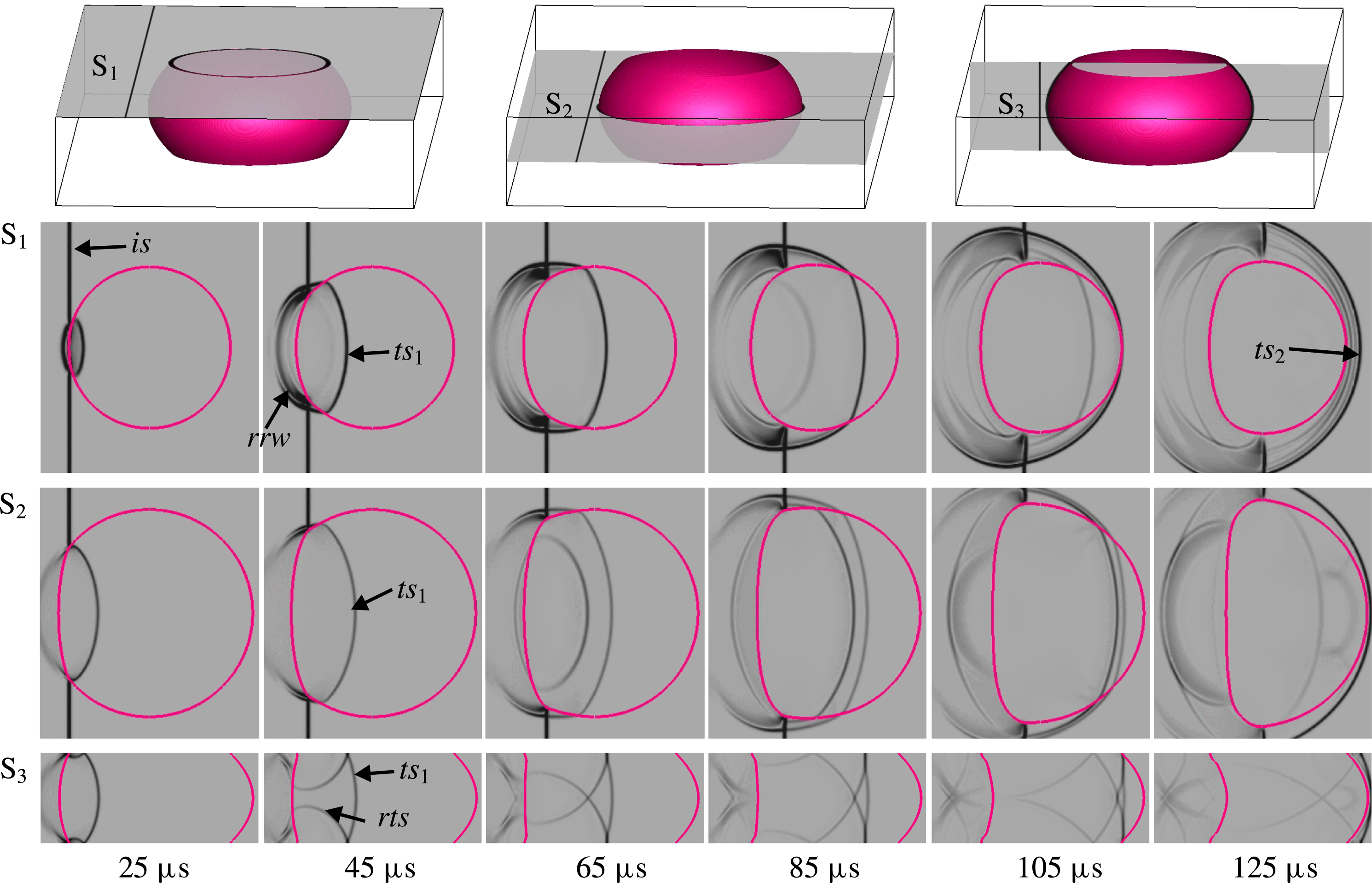
In the concave cylinder case, as presented in figure 10, the
 $is$
impacts the upper and bottom boundaries of the upstream interface in advance, and therefore the
 $ts_{1}$
and
 $rrw$
emerge in the form of two separate branches in S
 $_{3}$
slice
 $(18~\unicode[STIX]{x03BC}\text{s})$
. The branches of
 $ts_{1}$
propagate along the upstream interface from the boundary slices to the symmetry slice and merge quickly, forming a high pressure zone within the density inhomogeneity. The portion of the
 $ts_{1}$
near the symmetry slice seems much stronger than the other parts according to the intensity of the schlieren images at different slices. Then the two branching shocks generated behind the
 $ts_{1}$
propagate from the symmetry to the boundaries
 $(58~\unicode[STIX]{x03BC}\text{s})$
, and finally arrive at the top and bottom walls, forming the reflected transmitted shock (
 $rts$
). The
 $ts_{1}$
and the
 $rts$
maintain two curved lines in the S
 $_{1}$
slice
 $(78~\unicode[STIX]{x03BC}\text{s})$
. As time goes on, the
 $ts_{1}$
will interact with the downstream interface, and the formed
 $ts_{2}$
moves from the symmetry to the boundary slices
 $(98~\unicode[STIX]{x03BC}\text{s})$
and then departs from the density inhomogeneity
 $(118~\unicode[STIX]{x03BC}\text{s})$
. The complicated waves will cause significant pressure oscillations in the vicinity of the upstream and downstream interfaces, and further change the interface velocity.
Figure 11 presents the evolution of wave patterns and density inhomogeneity from different slices of the shocked convex cylinder. Distinguished from the concave case, the wave patterns in the convex case are a little more complicated. The
 $is$
collides with the upstream interface from S
 $_{2}$
slice at an earlier time, and the
 $ts_{1}$
and
 $rrw$
move along the interface from the symmetry to the boundary slices. After the
 $ts_{1}$
reaches the top and bottom boundaries, two reflected transmitted shocks emerge
 $(25~\unicode[STIX]{x03BC}\text{s})$
. The head of the
 $rts$
is in connection with the
 $ts_{1}$
, and its tail moves toward the symmetry plane
 $(45~\unicode[STIX]{x03BC}\text{s})$
. Subsequently, the two branches of
 $rts$
have a collision in the symmetry slice, resulting in the emergence of two shock waves at both sides of the upstream interface in the S
 $_{2}$
slice
 $(65~\unicode[STIX]{x03BC}\text{s})$
. As time goes on, more reflected waves arise behind the
 $ts_{2}$
and collide with the upstream interface
 $(85{-}105~\unicode[STIX]{x03BC}\text{s})$
. The
 $ts_{2}$
approaches the
 $ts_{1}$
within the density inhomogeneity, and finally passes across the downstream interface
 $(125~\unicode[STIX]{x03BC}\text{s})$
. In the process, the refracted waves connecting the
 $is$
at the external part of the interface have multiple components and induce complex pressure oscillations in the flow field.
Sketches of the pressure gradients in the vicinity of upstream and downstream interfaces shortly after the passage of incident and transmitted shocks for the concave (a) and convex (b) gas cylinders.

To vividly exhibit the pressure oscillations, the pressure gradients in the vicinity of the interface shortly after the passage of the
 $is$
across the upstream interface and the
 $ts_{1}$
across the downstream interface for the concave and convex gas cylinders are illustrated in figure 12. The upstream interface can be considered as a heavy–light (SF
 $_{6}$
–N
 $_{2}$
) gaseous boundary, while the downstream interface as a light–heavy (N
 $_{2}$
–SF
 $_{6}$
) gaseous boundary. As indicated in figures 10 and 11, the
 $rrw$
moving from right to left can be formed in the external of the upstream interface, while the
 $ts_{2}$
moving from left to right is formed in the external of the downstream interface. Therefore, the pressure gradients behind the
 $rrw$
and
 $ts_{2}$
in the horizontal
 $xy$
plane are all from right to left, similar to the 2-D case. However, the pressure gradients induced by the waves in the vertical
 $xz$
plane are significantly different for the concave and convex cases. Due to the opposite principal curvatures at any point of the concave cylinder, the pressure gradients in the vertical plane are from left to right, which will suppress the perturbation growth. On the contrary, the identical pressure gradients along the interface in the convex case will enhance the growth of perturbations. It can be concluded that the pressure oscillations induced by the waves contribute much to the deformation of the 3-D gas cylinders at the very early stages. As time proceeds, the pressure oscillations become weak, but the development of the evolving interface can be maintained, which would be attributed to the generation and distribution of baroclinic vorticity in the flow field.
The sketches of baroclinic vorticity distributions for the concave (a) and convex (b) gas cylinders in the vertical (
 $xz$
) and horizontal (
 $xy$
) planes.

Baroclinic vorticity deposited along the boundary (S
 $_{1}$
), symmetry (S
 $_{2}$
) and vertical (S
 $_{3}$
) slices of 2-D (a), concave (b) and convex (c) gas cylinders. The arrows indicate the directions of the interface velocity induced by vorticity.

5.3 Baroclinic vorticity
As the incident shock passes across the gas cylinder, the baroclinic vorticity is generated and distributed initially on the cylinder surface where the density gradients exist. The baroclinic vorticity is caused by the misalignment between the density (
 $\unicode[STIX]{x1D70C}$
) and pressure (
 $p$
) gradients (i.e.
 $\unicode[STIX]{x1D735}\unicode[STIX]{x1D70C}\times \unicode[STIX]{x1D735}p\neq 0$
), which has a large influence on the development of RMI (Brouillette Reference Brouillette2002; Ranjan et al.
Reference Ranjan, Oakley and Bonazza2011). For the 2-D gas cylinder, the density gradients at its surface are radially distributed in the
 $xy$
plane with their directions initially perpendicular to its symmetry axis. After the shock–cylinder interaction, the baroclinic vorticity with its direction in parallel with the symmetry axis is generated, inducing the gases in the vicinity of the deformed interface moving only in
 $xy$
plane. For the 3-D concave or convex gas cylinder, however, the density gradients at its surface point to different directions. The components of the induced velocities in the
 $z$
direction must be considered, which will result in 3-D movements of the deformed interface.
Figure 13 illustrates the baroclinic vorticity distributions for the concave and convex gas cylinders in the vertical (
 $xz$
) and horizontal (
 $xy$
) planes, respectively. Due to their symmetrical geometries, only the upper half of the gaseous inhomogeneity is considered. For the 3-D cases, the directions of density gradients along the boundary profiles are perpendicular to the interface and point from N
 $_{2}$
to SF
 $_{6}$
. In the
 $xy$
plane, the interface velocities induced by vorticity at points
 $\text{S}_{\text{L}}$
and
 $\text{S}_{\text{R}}$
are from left to right, similar to those in the 2-D case. However, in the
 $xz$
plane, they are a little complicated. For the concave cylinder, clockwise rotated vorticity is deposited on the upper half of the interface in the vertical plane, and the magnitude of the vorticity increases continuously along the vertical direction from the symmetry to the boundary planes, as shown in figure 13(a). The interface velocities induced by the vorticity have different magnitudes and directions. For an arbitrary point B (or C) on the downstream (or upstream) interface in the vertical plane, its velocity can be divided into two components: the negative velocity
 $v_{\text{B}-}$
(or
 $v_{\text{C}-}$
) induced by the vorticity between points B (or C) and
 $\text{B}_{\text{R}}$
(or
 $\text{B}_{\text{L}}$
), and the positive velocity
 $v_{\text{B}+}$
(or
 $v_{\text{C}+}$
) induced by the vorticity between points B (or C) and
 $\text{S}_{\text{R}}$
(or
 $\text{S}_{\text{L}}$
). In particular, the interface velocities induced by vorticity at points
 $\text{S}_{\text{L}}$
and
 $\text{S}_{\text{R}}$
(
 $v_{\text{SL}}$
and
 $v_{\text{SR}}$
) in the symmetry plane point from right to left, and the growth of perturbations are then suppressed. Differently, the vorticity-induced velocities at points
 $\text{B}_{\text{L}}$
and
 $\text{B}_{\text{R}}$
(
 $v_{\text{BL}}$
and
 $v_{\text{BR}}$
) in the boundary plane point from left to right. The velocity components along the
 $x$
direction (
 $v_{\text{BL}x}$
and
 $v_{\text{BR}x}$
) enhance the growth of perturbations. Therefore, the boundary interface moves faster than the symmetry interface, as observed in figure 8(a). On the contrary, for the convex gas cylinder, the counterclockwise vorticity is deposited on the upper half of the interface in
 $xz$
plane, as shown in figure 13(b). Therefore, the induced velocity at each point along the boundary profiles would be opposite in direction comparing with the concave gas cylinder. As a consequence, the interface in the symmetry plane moves faster than that in the boundary plane, as previously observed in figure 8(b).
Figure 14 shows the representative results of baroclinic vorticity deposited on the interfaces at different slices in numerical simulations shortly after the shock passage across the interfaces. The vorticity distributions for three cases are similar in the horizontal
 $xy$
planes (S
 $_{1}$
and S
 $_{2}$
). The vorticity is mainly generated along the interface boundaries where the density gradients exist. Counterclockwise vorticity with positive values is generated on the upper half of the cylinder cross-section, while clockwise vorticity with negative values is produced on the lower half. Moreover, the strength of vorticity increases continuously from the central points of upstream and downstream interfaces along the interface boundaries.
Along the S
 $_{3}$
slice, as shown in figure 14, the vorticity deposition behaves different for three cases. No vorticity is deposited on the generatrix of the 2-D cylinder and therefore there is no induced velocity in the
 $z$
direction. For the 3-D cases, however, the curvature of the generatrix along the S
 $_{3}$
slice results in the generation of additional vorticity deposition, inducing 3-D movement of the interfaces. Clockwise vorticity is deposited on the upper half of the concave cylinder, while counterclockwise vorticity is distributed on the upper half of the convex cylinder. On the contrary, the vorticity deposition is opposite on the lower half of two 3-D cases. The directions of the interface velocity induced by the vorticity are indicated in figure 14. In this work, the numerical results verify the qualitative analysis mentioned above and directly provide an understanding of experimental observations. It should be mentioned that here we mainly focus on the RMI induced by the weak shock. For strong shock cases, the compressible effects will be enhanced (Ranjan et al.
Reference Ranjan, Niederhaus, Motl, Anderson, Oakley and Bonazza2007, Reference Ranjan, Niederhaus, Oakley, Anderson, Bonazza and Greenough2008). Therefore, additional vorticity related to the compressibility would complicate the interface dynamics.
Experimental and numerical measurements of characteristic scales changing with time for the 2-D gas cylinder. The definitions of the length and the width of the evolving interface are inserted.

6 Quantitative analysis
6.1 Interface structures
Temporal variations of the interfacial characteristic scales (i.e. the length and the width of the evolving interface) for 2-D, concave and convex gas cylinders are plotted in figures 15 and 16, respectively. The measurements for three cases are taken from the sequence of images obtained in experimental observations and numerical simulations. The representative diagrams of the characteristic scales include the length and the width of the evolving interface. For the 3-D concave and convex cylinders, the data are extracted from both symmetric and boundary slices. The definition of the characteristic scales for the 2-D case is inserted in figure 15. For comparison, the dimensionless interface structures changing with the dimensionless time are further given in figure 17. The data are normalized by the local diameter
 $D$
of the initial interfaces (
 $D=35.0~\text{mm}$
for three cases along the boundary slice, and
 $D=27.4~\text{mm}$
, 35.0 mm and 45.0 mm for the concave, 2-D and convex cases along the symmetry slice, respectively) and by the characteristic time
 $t_{0}=D/V$
with
 $V$
the velocity jump of upstream interface due to the shock impact.
In the 2-D case, the length of the evolving interface decreases quickly after the arrival of the incident shock due to the distortion of the upstream interface. At approximately
 $200~\unicode[STIX]{x03BC}\text{s}$
, the length reaches a minimum value. As indicated in figure 5, the upstream interface is just flattened at this moment. Later, the variation with the time of the length turns into an increasing tendency. In this process, the width of the evolving interface first keeps growing with a decreasing velocity and then tends to a nearly constant value after
 $900~\unicode[STIX]{x03BC}\text{s}$
, at which the SF
 $_{6}$
jet reaches the downstream interface. When the SF
 $_{6}$
jet penetrates through the evolving interface, the vortex pair develops gradually with nearly constant distance between two counterparts. It can be easily seen that the numerical results agree well with the experimental ones, which further verifies the reliability of the numerical method developed in this work.
Experimental and numerical measurements of characteristic scales changing with time for the 3-D gas cylinder, including the length (a) and the width (b) for the concave cylinder and the length (c) and the width (d) for the convex cylinder, respectively. Due to the soap contamination at early stages, some of the experimental data are not given. The definition of the length and the width of the evolving interface is the same as that inserted in figure 15.

Numerical measurements of the dimensionless length (a) and width (b) changing with dimensionless time for the 2-D, concave and convex gas cylinders.

Figure 16 presents the variations with the time of the interface structures in the concave and convex cases. For the evolving interfaces in both symmetric and boundary slices, their lengths first decrease and then increase, while their widths keep constant in the very beginning, then increase gradually and later fluctuate slightly. Although the tendency of the characteristic scale variations with time for different slices of the 3-D cases is similar, large differences exist. For the concave case, the interface lengths in both symmetric and boundary slices decrease quickly due to the shock compression, as shown in figure 10 (from the very beginning to
 $118~\unicode[STIX]{x03BC}\text{s}$
). After approximately
 $240~\unicode[STIX]{x03BC}\text{s}$
, the interface lengths turn increasing as the SF
 $_{6}$
jet is formed and the upstream interface starts rolling, which can be found in figure 6. Later, the 3-D movement of the evolving interface becomes dominant in the flow field. The growth of the interface length in the symmetric slice is much smaller than that in the boundary slice, and the transportation of the test gas from symmetric to boundary slices results in the continuous variation of the interface lengths. For the convex case, the interface length in the symmetric slice decreases to the minimum value at approximately
 $300~\unicode[STIX]{x03BC}\text{s}$
, but the interface length in the boundary slice keeps decreasing for approximately
 $500~\unicode[STIX]{x03BC}\text{s}$
, which is much longer than that in the concave case. Due to the vortex dynamics, the test gas moves from boundary to symmetric slices, and the vortex pair develops in a 3-D behaviour. The widths of the evolving interface changing with fluctuations at later period reflect the deformation of the vortex pair.
Figure 17 indicates that the variations of the dimensionless interface length and width along different slices for the concave and convex cylinders are closely dependent on the directions of principal curvatures along the interface boundaries in comparison with the 2-D case. The dimensionless interface length along the symmetric slice of the concave cylinder or along the boundary slice of the convex cylinder is larger than that in the 2-D case at early stages, and then becomes smaller after a period; while the length along the boundary slice in the concave case or along the symmetric slice in the convex case, is smaller than that in the 2-D case at early stages, and then becomes larger. The interface length variations in the symmetric (boundary) slice of the concave cylinder and in the boundary (symmetric) slice of the convex cylinder suffer from similar 3-D effects, i.e. the pressure gradients and vorticity induction, which are essentially determined by the directions of principal curvatures on the interface. Different from the length history, the widths along the symmetric and boundary slices of both 3-D cylinders are all larger than that in the 2-D case in the beginning and then become smaller. Moreover, at late stages, the widths in both slices of each 3-D cylinder are nearly the same and also smaller than the 2-D counterpart. It is shown that the width of a 3-D cylinder at late stages of evolution is largely inhibited by the 3-D effects, regardless of its principal curvature directions.
Dimensionless displacements of the upstream interface changing with the dimensionless time along the symmetric slice for the 2-D, concave and convex N
 $_{2}$
cylinders.

6.2 Theoretical prediction of upstream interface velocities
It is instructive to investigate the connection between the 3-D cylinder distortion with the development of 3-D single-mode interface. Following the pioneering work of Haas & Sturtevant (Reference Haas and Sturtevant1987), the 2-D or the symmetric slice of the 3-D cylinder with a radius of
 $r$
is taken to be representative of a 2-D single-mode interface with an amplitude
 $a=r$
and a wavenumber
 $k=1/r$
. Figure 18 presents temporal variations of displacements of the upstream interface along the symmetric slice for the three cases. The displacement and the time are normalized by the corresponding cross-sectional cylinder diameter
 $D$
and the time duration
 $t_{0}=D/V$
, respectively. Because the characteristic point (i.e.
 $\text{S}_{\text{L}}$
in figure 14) in each case moves almost linearly, the interface velocities can be estimated as given in table 3. One can directly find that the experimental results are in good agreement with the numerical counterparts. The data also indicate that the local interface velocity of the convex cylinder is much larger than that of the 2-D cylinder, while the concave counterpart moves more slowly relative to the 2-D case. The velocity of the upstream interface,
 $V_{i}$
, of the cylinder after the shock impact can be described by the impulsive model (Richtmyer Reference Richtmyer1960):
 $$\begin{eqnarray}V_{i}/V=1-Z_{c}akA^{+},\end{eqnarray}$$
where
 $A^{+}$
stands for the postshock Atwood number and
 $Z_{c}=1-V/V_{s}$
for the shock-induced compression factor with
 $V_{s}$
the shock velocity. It is found that the theoretical prediction by the impulsive model is much larger than the experimental or numerical one for the 2-D case, which confirms the observation by Haas & Sturtevant (Reference Haas and Sturtevant1987). This over-prediction phenomenon can be attributed to the high amplitude effect (high amplitude of initial interface can significantly inhibit the perturbation growth rate) because the ratio of initial amplitude over the wavelength violates the requirement of the linear regime (
 $a_{0}/\unicode[STIX]{x1D706}\approx 0.16>0.1$
). Inspired by the work of Rikanati et al. (Reference Rikanati, Oron, Sadot and Shvarts2003), a reduction factor of
 $\unicode[STIX]{x1D719}$
(less than 1.0) multiplying the impulsive model prediction is proposed to quantitatively characterize the development of a high amplitude 2-D (HA–2-D) perturbation. Therefore, the movement of the upstream interface for the 2-D cylinder can be described as
 $$\begin{eqnarray}V_{i}/V=1-\unicode[STIX]{x1D719}Z_{c}akA^{+}.\end{eqnarray}$$
In the present work, a good agreement between the theoretical prediction of HA–2-D and the experimental or numerical result is achieved when
 $\unicode[STIX]{x1D719}=0.6$
.
Constants for 3-D single-mode interfaces corresponding to the 3-D cylinders.

Velocities of the characteristic points at early stages for all three cylinders. HA is short for high amplitude.

The 3-D cases are more complicated because the curvature effect of the curved catenary must be considered (Luo et al. Reference Luo, Wang and Si2013, Reference Luo, Guan, Zhai and Si2016c ). Therefore, a generalized 3-D single-mode interface is proposed here to represent the 3-D gas cylinder with arbitrary catenary curvature,
 $$\begin{eqnarray}\unicode[STIX]{x1D702}(y,z,t_{0})=(a_{1}\pm a_{2}\cos (k_{z}z))\cos (k_{y}y),\end{eqnarray}$$
where
 $k_{y}$
and
 $k_{z}$
are wavenumbers in the symmetry and vertical planes,
 $a_{1}$
and
 $a_{2}$
are constants representing the perturbation amplitudes at different slices of the interface, respectively. The positive sign in (6.3) corresponds to the 3-D single-mode interface with two identically signed principal curvatures, and the minus sign to the single-mode interface with two oppositely signed principal curvatures. For the concave cylinder, the interface radii in the symmetry and boundary slices are
 $r_{0}=13.7~\text{mm}$
and
 $r_{1}=17.5~\text{mm}$
, respectively, and the wavenumbers
 $k_{y}=k_{z}=1/r_{0}$
. The 3-D single-mode interface with an amplitude of
 $r_{0}$
at the
 $z=0$
plane (i.e.
 $a_{1}-a_{2}=r_{0}$
) and an amplitude of
 $r_{1}$
at the
 $z=10$
slice (i.e.
 $a_{1}+a_{2}\cos (10k_{z})=r_{1}$
) can be used to approximate the left boundary of the concave cylinder. For the convex cylinder, the interface radii in the symmetry and boundary slices are
 $r_{0}=22.5~\text{mm}$
and
 $r_{1}=17.5~\text{mm}$
, respectively, and the wavenumbers
 $k_{y}=1/r_{0}$
and
 $k_{z}=\unicode[STIX]{x0394}p/\unicode[STIX]{x1D70E}-k_{y}$
(the values of
 $\unicode[STIX]{x0394}p$
and
 $\unicode[STIX]{x1D70E}$
are given in § 2). Similarly, the 3-D single-mode interface with an amplitude of
 $r_{0}$
at the
 $z=0$
plane (i.e.
 $a_{1}+a_{2}=r_{0}$
) and an amplitude of
 $r_{1}$
at the
 $z=10$
slice (i.e.
 $a_{1}-a_{2}\cos (10/k_{z})=r_{1}$
) is able to represent the convex cylinder. The constants of 3-D single-mode interfaces corresponding to the concave and convex cylinders are listed in table 2.
For the 3-D single-mode interface described in (6.3), the overall perturbation growth along the symmetry slice in the linear stage, based on the 3-D stability analysis (Luo et al. Reference Luo, Wang and Si2013), can be given as,
 $$\begin{eqnarray}a(t)=Z_{c}a(t_{0})+VZ_{c}A^{+}\left(a_{1}k_{y}\pm a_{2}\sqrt{k_{y}^{2}+k_{z}^{2}}\right)(t-t_{0}).\end{eqnarray}$$
Therefore, similar to the 2-D case, the moving velocity
 $V_{s}$
of upstream interface on the 3-D gas cylinder along the symmetry slice can be estimated by the high amplitude 3-D (HA–3-D) prediction in the form of,
 $$\begin{eqnarray}V_{s}/V=1-\unicode[STIX]{x1D719}Z_{c}A^{+}\left(a_{1}k_{y}\pm a_{2}\sqrt{k_{y}^{2}+k_{z}^{2}}\right).\end{eqnarray}$$
It is worth noting that the present 3-D model is applicable for predicting the upstream interface velocity of 3-D interfaces with any principal curvatures. If the catenary principal curvature disappears (i.e.
 $a_{2}=0$
), equation (6.5) will be reduced to the 2-D model. As shown in table 3, keeping the same value
 $\unicode[STIX]{x1D719}=0.6$
as in the 2-D case, this HA–3-D model well predicts the upstream interface motion for 2-D and 3-D gas cylinders.
7 Conclusions
Interactions of a planar shock wave with concave, convex and 2-D light gas cylinders have been investigated experimentally and numerically. The initial interfaces with well-characterized shapes and sharp SF
 $_{6}$
/N
 $_{2}$
boundaries are generated by adjusting the pressure within the cylindrical volume according to the circular wire-restriction method based on the soap film technique. Specifically, the convex/concave gas cylinders possess identically/oppositely signed principal curvatures along the interface boundaries. The high-speed schlieren photography is employed to record the complete evolution of wave patterns and interface deformations during each experimental run. The 3-D morphologies of the evolving interfaces are further reconstructed by numerical simulations, which combine the high-order weighted essentially non-oscillatory construction and the double-flux scheme. The numerical and experimental results are in good agreement. It is found that interesting phenomena exist in the evolution of 3-D gas cylinders. Due to the curved catenaries of the convex and concave gas cylinders, the transmitted shock undergoes multiple reflections between the top and the bottom boundaries, resulting in the emergence of double transmitted shock structure. The pressure oscillations arise in the vicinity of the evolving interfaces, and to an extent manipulate the interface movement at the very early stages. After the shock wave passes across the cylinder, baroclinic vorticity deposited at the gas cylinder dominates the interface deformation. For the 2-D case, the vorticity mainly has the direction normal to the horizontal plane, while the curved catenary for the 3-D cylinders causes additional baroclinic vorticity parallel to horizontal plane. Moreover, the variations with the time of the interface structures for different gas cylinders are extracted quantitatively, and large differences exist among them. The interface deformations in the symmetric and boundary slices of the concave and convex cylinders suffer from similar 3-D effects due to their different principal curvatures of initial interfaces in comparison with the 2-D case. It is also found that the upstream interface along the symmetric slice of the convex cylinder moves faster than that of the 2-D case, while the concave counterpart propagates more slowly. The calculated interface velocities have been well predicted by a generalized 3-D high amplitude theoretical model. In this work, we only examine the N
 $_{2}$
cylinders surrounded by SF
 $_{6}$
interacting with a weakly planar shock wave. More phenomena are expected if considering a wider range of gaseous combinations and incident shock strengths.
Acknowledgements
This work was supported by the National Natural Science Foundation of China (grant nos. 11272308, NSAF U1530103, 11625211 and 11621202), the China Postdoctoral Science Foundation (2016M602026) and the Fundamental Research Funds for Central Universities.
Supplementary movies
Supplementary movies are available at https://doi.org/10.1017/jfm.2017.528.



