I. INTRODUCTION
Microstrip antennas have been used in microwave application due to their well-known features of low cost, low profile, and light weight. However, their performance is limited by narrow impedance bandwidth, low efficiency, and poor polarization purity. Many works, such as stacking the patches [Reference Nishiyama, Aikawa and Egashira1], using metamaterial [Reference Palandoken, Grede and Henke2], loading by electromagnetic band gap (EBG) [Reference Ripin, Sulaiman, Baba and Subahir3], and many other techniques, have been done to resolve some of these limitations.
On the other side, waveguide slot antennas with high gain, high efficiency, and low cross-polarization level are interesting structures in radar applications and communication systems; but the waveguide structures are bulky, expensive to produce, and hard to integrate with the planar components. Substrate integrated waveguides (SIWs) can be used as the alternative structures to eliminate some deficiencies of the waveguides. It is implemented by low-cost printed circuit board (PCB) technology without manufacturing difficulties of the waveguides.
Slot radiators can be used as the feeding structures for some antennas. In this case, the antenna can be considered as the series-fed structure with high radiation efficiency. Unlike corporate networks, series-feeding technique minimizes the insertion and radiation loss of the feeding line by reducing length of it [Reference Metzler4]; therefore, the antenna has high radiation efficiency.
The circular polarized antennas can give better performance against reflection, absorption, penetration, and bending effects as compared with the linearly polarized antennas. The multipath fading effects due to the phase difference are also less destructive in circularly polarized antennas. Circular polarization (CP) in microstrip antennas can be accomplished by using single-, double-, or multiple-feed structures. The single-feed structure reduces the complexity, weight, and loss of the antenna, but it could not provide wide axial ratio bandwidth as much as double-feed networks.
Using the advantages of series-feeding and SIW structures, a new synthetic circular polarized antenna, consisted of microstrip patch and slot on the SIW, is proposed. The similar design is accomplished in [Reference Sabri, Amiri and Forooraghi5] for linear polarization in two distinct bands. In this paper, it is shown that the large CP bandwidth can be achieved by single feeding. To get high gain and wide impedance bandwidth, the resonance frequencies of the slot and the patch, as the first and second radiators, respectively, are set near to each other. An indented-shaped patch is used to achieve CP [Reference Shahabadi, Busuioc, Borji and Safavi-Naeini6]. A 1 × 4 linear array with CP and simple single-fed structure is designed and fabricated, which increases the radiation efficiency of the antenna. As the antenna works in X-band, it can be used in earth-satellite communication, which needs CP antennas due to their immunity to Faraday rotation. Since CP antennas can filter out the reflected signals, they are appropriate for satellite-based navigation system [Reference Narbudowicz7].
II. ANTENNA DESIGN
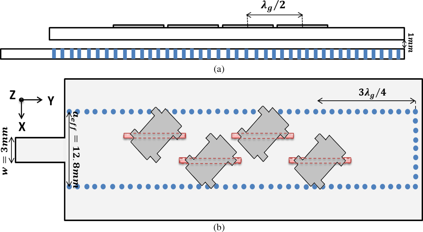
The antenna consists of microstrip patches that are loaded on SIW-based slot radiators. Schematic of the antenna is illustrated in Fig. 1. SIW is implemented on Rogers 4003 with ε r = 3.55, loss tangent of 0.0027, and thickness of 1.32 mm. The end of the SIW is closed to block slant pattern for a frequency change, so it is a resonant array. Vias have the distance of 1.5 mm in side walls and 1.6 mm at the end wall with the common diameter of 0.8 mm. Slots on SIWs are half a wavelength apart to feed the patches in-phase. Distance of the last slot from the short wall of the SIW is 3λ g /4 to put the slots at the peaks of standing waves, where λ g is the wavelength inside the SIW.
(a) Side and (b) top view of the antenna.

Microstrip patches are etched on Taconic TLY with dielectric constant of 2.17 and loss tangent of 0.0027 and thickness of 1.5 mm. They are fed by slots on the SIW. This kind of feeding network for microstrip antenna not only makes it have a higher gain and wider impedance bandwidth but also makes it easy to control the dielectric constant of the feed line and radiating patch, separately. Thus, the unwanted radiating field is reduced by choosing high permittivity substrate for the feed line. Waveguide-fed microstrip antennas benefit from the high efficiency, and choosing the low permittivity substrate for patches increases the radiation efficiency more. There is an air gap between patches and SIW to match the loaded slots with the characteristic impedance of the SIW and provide wide impedance bandwidth [Reference Rowe, Waterhouse, Nirmalathas and Novak8].
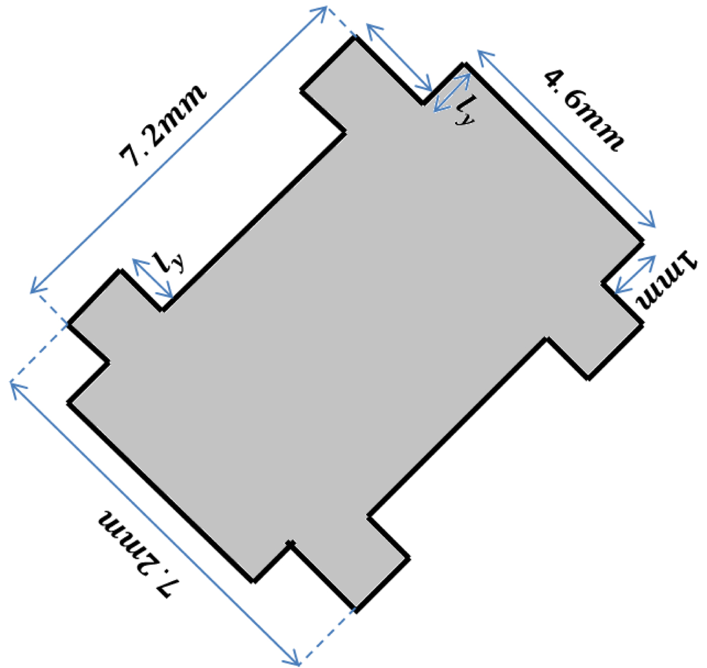
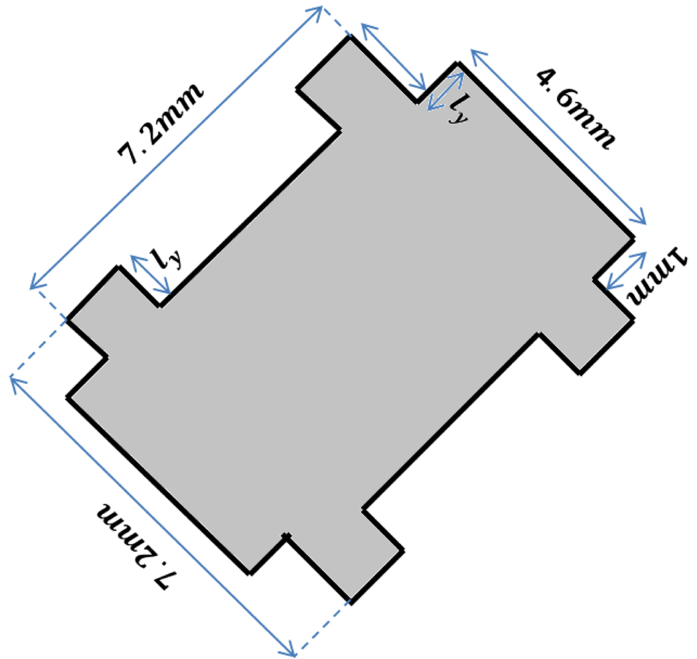
A 45° rotated square patch on a longitudinal slot can excite two orthogonal modes with equal amplitude. These modes should be 90° out of phase to obtain CP. This can be achieved by shifting the resonance frequencies of two modes; the phase difference between two modes can be provided by a time delay in their excitation signal or changing the resonance frequency of each mode (since Δϕ ∝ ωΔt). The side of the patch is lengthened by indenting to lower the resonance frequency and the other side is truncated to raise the resonance frequency. This configuration is illustrated in Fig. 2. Increasing the length of the l
y
makes the array to have a good axial ratio bandwidth in exchange of lowering the impedance bandwidth. It seems that varying the dimensions of the patch changes its resonance frequency, which is no longer matched with resonance frequency of slot, but it regulates the phase difference to have a wider CP bandwidth. Increasing the length of slot rectifies this deficiency and increases the impedance bandwidth. The appropriate length of slots on the SIW, for efficient radiation to the free space, is
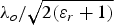 $\lambda _o /\sqrt {2(\varepsilon _r + 1)} $
[Reference Sammeta, Reddy, Glisson and Kishk9]. Here, the slots are radiating to an effective media, free space, and substrate beneath the patches, so the effective permittivity is larger than free space and the slot length needs to be smaller than what is stated in formula. As the shaped patches disturb the scattering parameter of the antenna, the length of the slots is optimized (12 mm) to provide an acceptable return loss and axial ratio bandwidth at the same time.
Configuration of the designed patch to produce circular polarization.
III. RESULTS
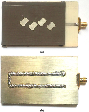
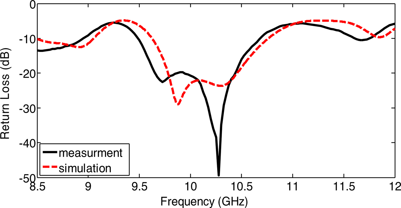
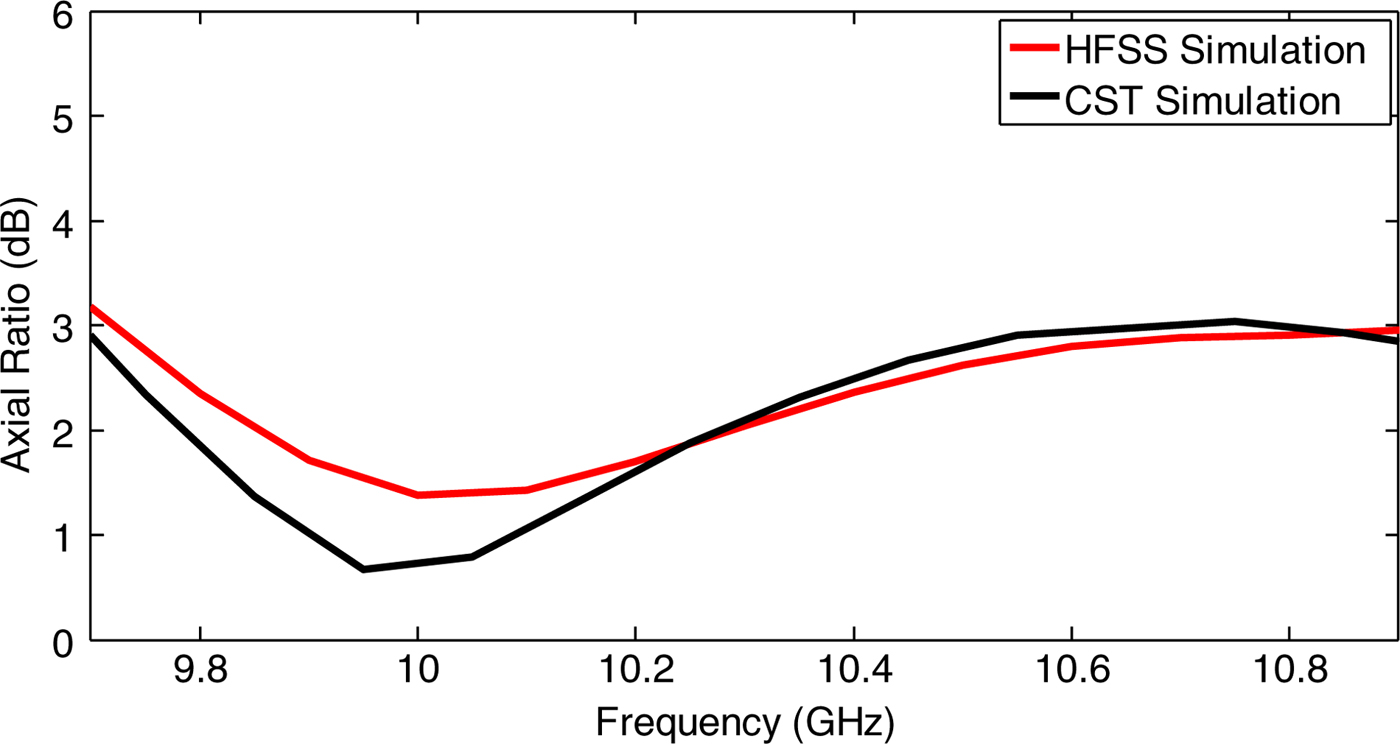
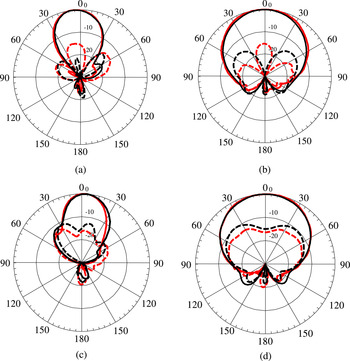
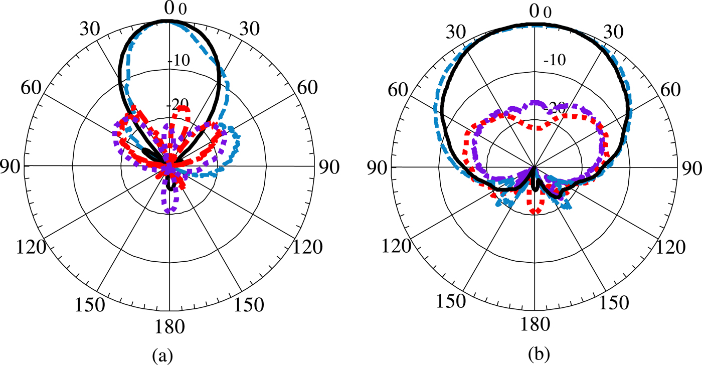
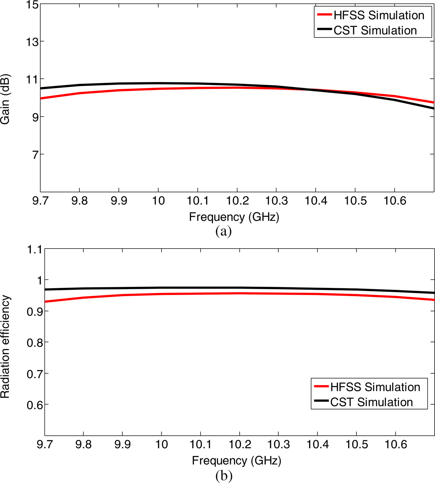
Figure 3 shows the prototype of the fabricated antenna. Two 20 and 32 mil layers of Rogers 4003 with overall dimension of 4 × 8.5 cm2 are glued to each other to get the desired thickness of 1.32 mm. Both patch and feed network are fabricated with low-cost PCB process. Slots are etched on SIW, fed by a 3 mm width microstrip line that connects the 50 Ω sub-miniature version A (SMA) to the SIW. The substrate of the patches with overall size of 4 × 7 cm2 is placed above the SIW using four stands. These stands are away from the radiation slots of the antenna and do not cause significant effect on the antenna performance. The effect of stands is considered in simulation results. The measured and simulated return loss of the antenna is depicted in Fig. 4. It is shown that wide impedance bandwidth of 11.8% is obtained in X-band. The measured bandwidth of the antenna is greater than the simulated one since the fabricated antenna is radiated in an unbounded space. Antenna has the axial ratio <3 dB over the wide frequency range of 1.12 GHz with the center frequency of 10.3 GHz as depicted in Fig. 5. It is much more than the typical axial ratio bandwidth for single-fed circular polarized microstrip antenna. The simulation results of two commercial softwares (CST and HFSS) are compared to confirm the accuracy of results. The simulated radiation pattern of the antenna with co- and cross-polarization is represented at different frequencies in Fig. 6. The measured pattern at the center frequency is similar to the simulated one as shown in Fig. 7. Good cross-polarization level more than 15 dB is achieved in both cutting planes of each frequency. It is seen that the sidelobe level at the end of the frequency band is changed, but still the main lobe direction of the antenna is at boresight. The simulated gain and radiation efficiency of the antenna are illustrated in Fig. 8. It is shown that antenna has the maximum gain of 10.5 dB and high radiation efficiency more than 90% in its operation bandwidth.
(a) Top and (b) bottom side of the fabricated antenna.

Simulated and measured return loss of the antenna.

Simulated axial ratio of the antenna.

Simulated co-polarization (solid line) and cross-polarization (dash line) pattern of the antenna in YZ-plane of the (a) 9.72 GHz and (c) 10.5 GHz, and XZ-plane of the (b) 9.72 GHz and (d) 10.5 GHz. CST and HFSS simulations are shown with black and red colors, respectively.

Simulated co-polarization (solid line), simulated cross-polarization (dot line) and measured co-polarization (dash line) and measured cross-polarization (dash-dot line) pattern of the antenna at (a) YZ-plane, and (b) XZ-plane in 10.1 GHz.

Simulated (a) gain and (b) radiation efficiency of the antenna.

Several techniques have been done to attain CP in single-fed microstrip antenna. C- [Reference Chen and Qing10], F- [Reference Yong, Chen and Alphones11], and S-shaped slots [Reference Qing and Chen12] are used to give the microstrip patches the proper perturbation, but only a few percentage of axial ratio bandwidth is achieved. In [Reference Liu13], stacking method has been used to obtain CP, but only 2.5% axial ratio bandwidth with low radiation efficiency of 40–50% are achieved. The purposed antenna at this paper provides good performance in terms of bandwidth and radiation efficiency compared with the above mentioned works.
IV. CONCLUSION
A 1 × 4 series-fed microstrip antenna array for CP is purposed. The patches are fed through slots on the SIW. Wide impedance bandwidth of 11.8% and axial ratio bandwidth 10.9% are achieved by adjusting adjacent resonance frequency for the slots and microstrip patches. Series-feeding technique makes the antenna have high radiation efficiency over 90%, while the shaped patches cause CP.
Laaya Sabri received her B.S. degree in Electrical Engineering in 2011 from Tabriz University, Tabriz, Iran, and her M.S. degree in Electrical Engineering in 2013 from Tarbiat Modares University (TMU), Tehran, Iran. She is a Ph.D. candidate in Electrical Engineering at TMU. Her current research interests are Plasmonics, LSPR, Bio sensors.
Nasrin Amiri received the B.S. degree in electrical engineering from the Khajeh Nassir University (KNTU), in 2003, and the MSc. and Ph.D. degree in electrical engineering from the Tarbiat Modares University (TMU), Iran, in 2010. She is now assistant professor at South Tehran Branch, Azad University. Her research interests include analytical and numerical modeling of metamaterials, homogenization of metamaterials and effective medium models, and antenna theory and design.
 Keyvan Forooraghi received the M.Sc. degree in electrical engineering, the licentiate of technology degree and the Ph.D. degree in electrical engineering in 1991 from Chalmers University of Technology, Gothenburg, Sweden. He worked as a researcher at Chalmers University of Technology from 1991 to 1992. In 1992, he joined the Department of Computer and Electrical Engineering, Tarbiat Modares University. Presently he is a full professor at the Communication Group. His research interests include electromagnetic theory and computational electromagnetic and antenna theory.