1. Introduction
Exoskeletons are becoming increasingly important when facing complex tasks and harsh environments [Reference Reed, Ebert and Vallier1–Reference Ercolini, Trigili, Baldoni, Crea and Vitiello6]. Wearing an exoskeleton during daily physical labor can reduce muscle fatigue and improve work efficiency [Reference Cong, Gao, Wang, He, Mao, Long and Dong7–Reference Verdel, Bastide, Vignais, Bruneau and Berret11]. As a result, much research has focused on this critical topic, with several technical insights being proposed and addressed. We will summarize them as follows.
One key goal of assistive exoskeleton technology is to provide users with a larger range of motion. To achieve this, some researchers have conducted studies on this aspect [Reference Carbone and Copilusi12–Reference Curcio, Lago and Carbone14]. Nicola Vitiello [Reference Vitiello, Lenzi, Roccella, De Rossi, Cattin, Giovacchini, Vecchi and Carrozza15] proposed a powered exoskeleton mechanism. Its rotation angle on the horizontal axis is limited to 100°. However, the normal rotation angle of the human elbow joint can reach 145° [Reference Van Tunen, Van Lieshout, Mader and Den Hartog16], and the 3D-printed components used for the arm connection, along with rigid parts, increase user discomfort. Zhao [Reference Zhao, Wang, Sun, Zhang and Vänni17] introduced a ball joint passive exoskeleton, which significantly reduces shoulder deltoid muscle activity. Experimental data show that the maximum rotation angle of the ball joint is limited to −45° to 45°, which is inadequate for the complex movements of the human body. Even during shoulder flexion alone, the shoulder joint already achieves a 180° flexion angle [Reference Veeger and Van Der Helm18]. Zhu [Reference Zhu, Zhang, Li and Zhao19] also designed a passive upper limb assistive exoskeleton that uses spring-based energy storage components. It has an expanded range of motion compared to the former, but it only provides a joint rotation range of −60° to 60°, which falls short of the normal range of human motion [Reference Carbone and Nemec20]. Li [Reference Li, Song, Zheng, Zhang, Shen and Chen21] developed a passive upper limb exoskeleton weighing just 3.3 kg, minimizing the burden on the human body. However, data show that when wearing the exoskeleton, the range of motion is identical to that of the human body, leading to some loss of flexibility due to the lack of additional motion space redundancy. Therefore, our primary goal is to enable the exoskeleton mechanism to better adapt to the human body’s motion space.
The assistive effect of the exoskeleton is the second key factor in the research process [Reference Cao, Li, Li, Li and Wang22–Reference Li, Zhang, Jin, Chen and Ye24]. While ensuring the effectiveness of the assistive exoskeleton, its own weight and effectiveness must be balanced to reduce the burden on the user’s body [Reference Han, Xu, Zhang, Xu, Xiong, Cao, Liang, Zheng, Sun, Zhai, Sun and Wang25–Reference Ferreira, de Paula Rúbio, Dutra, Van Petten and Vimieiro29]. Hu [Reference Shi30] proposed an energy-harvesting exoskeleton that collects vibration energy during human walking using hydraulic devices with an output power of 4.75 W. However, its overall weight reaches 15 kg, which undoubtedly imposes a considerable burden on the human body. Wang [Reference Wang, Yang, Sun, Chen, Lyu, Shi and Chen31] proposed a passive elbow exoskeleton that releases the negative work collected by the spring during the shoulder’s downward movement through a ratchet mechanism. Even though its mass is significantly smaller compared to the former, the full 4.3 kg of its weight acts directly on the arm. Additionally, its mass-to-assistance ratio for the human body is only 0.86. For assistive exoskeletons, the results are less than ideal. Zhang [Reference Zhang, Zhu, Li, Lin and Zhao32] proposed an upper limb exoskeleton mechanism. Based on human biomechanics and control strategies, it offers an optimal mass-to-assistance ratio of 41. Nevertheless, its 12 kg weight impacts user mobility. Zhou [Reference Ren, Zhou, Zhang, Zhang and Tan33] proposed a lower limb assistive device with an output power of 3.16 W. Its weight is significantly reduced, with an overall weight of 406 g. It uses a flexible rack as the transmission component, greatly improving the mechanism’s adaptability to the human body. However, after being worn, its weight distribution is too concentrated, causing significant lateral vibration of the device during use. This vibration undoubtedly affects the user’s movement balance and use experience.
The comfort of the exoskeleton assistance mechanism is the final hurdle in the research process. The Dasheek team [34] designed a seven-degree-of-freedom mechanism that can accurately simulate upper limb arm movements. Its redundant degrees of freedom make it especially suitable for complex upper limb motions, reducing interference with the body’s movements. However, the increased number of degrees of freedom also raises the difficulty of user control. Haieh [Reference Hsieh, Chen, Chien and Lan35] designed a lightweight dual-spherical shoulder exoskeleton, improving the wearing experience, but it is complex and takes up considerable space. Other researchers have designed biomimetic joints to reduce interference between the exoskeleton and the body. For example, J. M. P. Gunasekara [Reference Gunasekara, Gopura and Jayawardena36] proposed a corrugated structure for the elbow joint coupling, which increased flexibility and the range of motion. Its redundant controllability index improved by 21.13%. Miguel Nobre Castro [Reference Castro, Rasmussen, Andersen and Bai37] and Felix [Reference Balser, Desai, Ekizoglou and Bai38] developed a three-degrees-of-freedom scissor mechanism. Felix’s spherical mechanism can cover nearly 95% of the shoulder’s range of motion. However, during use, the rigid structure can create sharp angles that may cause skin damage. In environments with higher physical demand, the comfort level for the user is relatively low.
There are relatively few evaluation systems specifically for the comfort of upper limb exoskeletons. A similar approach is proposed by Matra [Reference Gherardini, Ianniciello, Masiero, Paggetti, D’Accolti, La Frazia, Mani, Dalise, Dejanovic, Fragapane, Maggiani, Ipponi, Controzzi, Nicastro, Chisari, Andreani and Cipriani39], who developed a human–machine performance evaluation standard for lower limb exoskeletons. They assessed the efficiency and precision of assistive exoskeletons through gait experiments under different task conditions. Similarly, S. V. Sarkisian has conducted related work focusing on enhancing knee joint comfort [Reference Sarkisian, Ishmael and Lenzi40].
The contributions of our work can be summarized as follows:
-
1. A flexible power assistive exoskeleton (FPAE) is proposed. It boasts a more comprehensive range of motion, catering to the complex actives of daily living for humans.
-
2. The FPAE employs a distributed energy storage principle, enabling it to achieve high assistance efficiency despite its lightweight construction.
-
3. The soft structure inherently offers a high degree of comfort to the human body. This paper also introduces a novel evaluation method, providing a scientific basis and new perspective for assessing the comfort of exoskeleton systems.
2. Working principle and theoretical analysis
2.1. Structural design
The FPAE is designed based on biomimetic principles. Figure 1 gives a scheme of the FPAE. According to the composition of the human upper limb, including the bone, anadesma, muscles, and skin, as shown in Figure 1(a). The FPAE is designed with spring wire, springs, a rivet, and a nylon strap. The spring wire acts as the bone, the rivet function as the anadesma, the springs functions as muscles, and the nylon strap serves as the skin. This biomimetic design ensures good comfort when wearing the FPAE.
Scheme of the FPAE. (a) The biomimetic principle of the FPAE. (b) Structural composition of the FPAE. (c) Two shoulder movements and the working status of the core structure. (d) The distributed energy storage principle of the FPAE.

The FPAE is secured to the shoulder using nylon straps. The structural composition of FPAE is detailed in Figure 1(b). The FPAE uses TPV material as the flexible frame material, which fits the wearer’s body well. The other end of the FPAE is also fixed around the upper arm using nylon straps in a wrapping manner. The spring constitutes the majority of the FPAE core structure. The three internal energy-storage springs serve as primary energy accumulators. During various human motion processes, the front spring, central spring, and rear spring distributed across the shoulder undergo different degrees of deformation. In this manner, gravitational potential energy generated during downward shoulder movement is captured and utilized to assist in subsequent upward shoulder lifting. The front spring wire, central spring wire, and rear spring wire primarily function to support the structure while also contributing to energy harvesting. Ultimately, upper rivets secure all components to the upper shoulder fixator, and lower rivets fix them to the lower shoulder fixator.
2.2. Working principle
In the shoulder’s daily activities, two movements are particularly distinctive: the swinging motion along the body and the downward motion towards the body, as shown in Figure 1(c). Other movements can be seen as combinations of these two types.
For swinging motion, the deformation of the front spring, rear spring, front spring wire, and rear spring wire primarily drives the motion. The corresponding components are highlighted red in Figure 1(c). During the downward motion towards the body, the three springs distributed at the shoulder, along with the central spring wire, are involved. The corresponding springs are highlighted in red.
During arm swing motion, the descending upper arm elongates the front spring and compresses the rear spring, bending their wires. These four deforming components convert gravitational potential energy into elastic potential energy stored in the FPAE. During subsequent elevation, the springs return to their original lengths, converting this stored energy into kinetic energy that assists the upward motion.
In downward motion, the front spring, rear spring, center spring, and center spring wire elongate. This deformation captures gravitational potential energy as elastic potential energy within these four components, reducing the negative work required by the arm to control descent. Upon elevation, their contraction reconverts the stored energy into kinetic energy, aiding upward movement. In the other movements, all the spring components undergo stretching or bending, storing energy in the FPAE accordingly.
Finally, the concept of distributed energy storage proposed in this paper is illustrated in Figure 1(d). When the user wears the FPAE, the springs and spring wires cover the surface of the shoulder like a mesh. The energy collected from the shoulder is converted into elastic potential energy and distributed across the surface of the upper arm. Compared to centralized energy storage assistive exoskeletons (such as the energy storage springs in [Reference Wang, Yang, Sun, Chen, Lyu, Shi and Chen31]), this distributed energy storage method offers greater storage capacity, a better fit, and is also beneficial for the subsequent arrangement of components.
2.3. Modeling and analysis
In this section, a theoretical model is developed for the proposed distributed energy storage exoskeleton, which is then utilized to assess its assistive capacity [Reference Zhou, Bai, Andersen and Rasmussen41, Reference Yu and Bai42].
The relative motion relationship between the exoskeleton and the skeletal joints can be expressed by
 \begin{align} {\boldsymbol{F}}={\boldsymbol{C}}{\boldsymbol{f}} \end{align}
where F represents the total sum of all external loads and inertial forces acting on the human body; it is a kind of generalized force. C represents the coefficient matrix generated by human muscle tissues, and f represents the force of upper limb muscle.
The range of upper limb muscle force is defined as (2), N represents the upper limit of f.
 \begin{align} 0\leq f\leq N \end{align}
To simulate the differences in muscle activity under various movements, (1) can be rewritten as
 \begin{align} {\boldsymbol{F}}={\boldsymbol{C}}_{1}\cdot {\boldsymbol{f}}_{1}+\cdots +{\boldsymbol{C}}_{{\boldsymbol{\textit{i}}}}\cdot {\boldsymbol{f}}_{{\boldsymbol{\textit{i}}}}+\cdots +{\boldsymbol{C}}_{{\boldsymbol{\textit{n}}}}\cdot {\boldsymbol{f}}_{{\boldsymbol{\textit{n}}}},{\boldsymbol{\textit{i}}}=1,\ldots ,{\boldsymbol{\textit{n}}} \end{align}
where f i represents the force generated by the i-th muscle,C i is the term in the coefficient matrix C. When a specific muscle is not involved in the movement, its corresponding muscle force will be set to be zero.
To describe the motion system of the human body wearing an assistive exoskeleton, the Newton–Euler equations are used to establish the dynamic motion equations, as shown in
 \begin{align} \left[\begin{array}{c@{\quad}c} m_{0} & 0\\ 0 & J_{0} \end{array}\right]\ddot{q}+\left[\begin{array}{c} 0\\ \omega \times J_{0}\omega \end{array}\right]=g \end{align}
where q represents the unit vector encompassing the coordinate directions along the x, y, and z-axis. The ω represents the angular velocity measured in the fixed reference frame, m 0 represents the mass that muscle needs to bear, J 0 represents the inertia the muscle needs to bear, and g represents the magnitude of the force that needs to be provided accordingly. And g can be rewritten as
 \begin{align} g=F+g^{\mathrm{app}} \end{align}
where g app represents the externally applied force.
In the FPAE, the primary component is the spring. Therefore, the externally applied force needs to be considered as
 \begin{align} g^{\mathrm{app}}=k{\unicode{x0394}} l \end{align}
where k is the stiffness of the spring and Δl is the distance between nodes.
Figure 2 shows the modeling and analysis of the FPAE. During human motion, the three spring wires and three springs on the shoulders undergo different stretching and bending due to varying force angles. An upper limb movement model is given in Figure 2(a). The system O represents the origin of the upper limb coordinate system, and {O} represents the origin of the coordinate system after shoulder movement. The motion is decomposed into rotations around the z-axis and y-axis, corresponding to angles ϕ and τ.
The modeling and analysis of the FPAE. (a) Upper limb motion model. (b) Ball-and-stick model of the FPAE. (c) Simulation results.

We develop a spring-ball-stick model based on the angles formed during the upper limb motion, which is shown in Figure 2(b). Since the energy storage principles of the three springs are identical, only one is analyzed. The spring wire is divided into node q i + 1 (0 ≤ i ≤ n) and small elastic rod segment l i (0 ≤ i ≤ n).
To accurately describe the geometric and mechanical characteristics of the FPAE, the mathematical expressions for the unit vector and its magnitude are given in
 \begin{align} \left\{\begin{array}{l} \left| \overset{\rightarrow }{e_{i}}\right| ={\unicode{x0394}} l_{{_{i}}}\\ {\unicode{x0394}} l_{i}=l_{\mathrm{m}}\sin \alpha _{i} \end{array}\right. \end{align}
where
 $\vec {e}_{i}$
represents the motion vector of the node (i = 1, 2, 3, …, n), Δ l
i
represents the distance between nodes changes, l
m represents the distance from the shoulder rotation center to the skin surface, and α
i
represents the spatial rotation angle, which is determined by
 $\varphi_{i}$
and
 $\tau_{i}$
together. C
b represents the coefficient matrix of the force generated by muscle stretching.
At this point, f can be expressed as
 \begin{align} f={\boldsymbol{C}}_{\mathrm{b}}\cdot l_{\mathrm{m}}\sin \alpha \end{align}
Equation (3) is transformed into
 \begin{align} {\boldsymbol{F}}={\boldsymbol{\textit{C}}}_{1}\cdot {\boldsymbol{\textit{C}}}_{\mathrm{b}}\cdot {\boldsymbol{\textit{l}}}_{\mathrm{m}}\sin \alpha _{1}+{\boldsymbol{\textit{C}}}_{{\boldsymbol{\textit{i}}}}\cdot {\boldsymbol{\textit{C}}}_{\mathrm{b}}\cdot {\boldsymbol{\textit{l}}}_{\mathrm{m}}\sin \alpha _{{\boldsymbol{\textit{i}}}}+\cdots +{\boldsymbol{\textit{C}}}_{{\boldsymbol{\textit{n}}}}\cdot {\boldsymbol{\textit{C}}}_{\mathrm{b}}\cdot {\boldsymbol{\textit{l}}}_{\mathrm{m}}\sin \alpha _{{\boldsymbol{\textit{n}}}},{\boldsymbol{\textit{i}}}=1,\ldots ,{\boldsymbol{\textit{n}}} \end{align}
Accordingly, the elastic stretching energy and bending energy in the FPAE are represented by
 \begin{align} E_{\mathrm{s}}=\sum _{i=1}^{n}\frac{1}{2}k_{\mathrm{s}}\cdot \left({\unicode{x0394}} l_{i}\right)^{2} \end{align}
 \begin{align} E_{\mathrm{b}}=\sum _{i=1}^{n}\frac{1}{2}k_{\mathrm{b}}\cdot \left({\unicode{x0394}} \varphi _{i}\right)^{2} \end{align}
where E s represents the stretching potential energy, E b represents the bending potential energy, k s and k b are the axial stiffness and the bending stiffness, respectively.
In (11), Δϕ i is represented as
 \begin{align} {\unicode{x0394}} \varphi _{i}=\varphi _{i}-\varphi _{i-1} \end{align}
Substituting (7) into (10) gets
 \begin{align} E_{\mathrm{s}}=\sum _{i=1}^{n}\frac{1}{2}k_{\mathrm{s}}\cdot l_{\mathrm{m}}^{2}\cdot \sin ^{2}\tau _{i} \end{align}
Finally, the output work when wearing the FPAE can be expressed as the sum of the product of the elastic rod length changes and the total output force, as shown in
 \begin{align} \begin{array}{l} \mathrm{d}W=g=F+g^{\mathrm{app}}\\ \,\,\,\,\,\,\,\,\,\,\,={\boldsymbol{C}}\cdot {\boldsymbol{C}}_{\mathrm{b}}\cdot l_{m}\cdot \sin \alpha +\mathrm{d}E_{\mathrm{s}}+\mathrm{d}E_{\mathrm{b}} \end{array} \end{align}
Substituting (13), (15) into (16) gets
 \begin{align} \mathrm{d}W&={\boldsymbol{C}}\cdot {\boldsymbol{C}}_{\mathrm{b}}\cdot l_{m}\cdot \sum _{i=1}^{n}\left(\sin \tau _{i}\right)+{\boldsymbol{C}}\cdot {\boldsymbol{C}}_{\mathrm{b}}\cdot l_{m}\cdot \sum _{i=1}^{n}\left(\sin \varphi _{i}\right)\cdots \nonumber\\ &\quad+\sum _{j=1}^{2}\left[\frac{1}{2}k_{\mathrm{s}j}\cdot l_{m}^{2}\cdot \left(\sin ^{2}\tau _{1i}+\sin ^{2}\tau _{2i}+\sin ^{2}\tau _{3i}\right)\right]\nonumber\\ &\quad+\sum _{j=1}^{2}\left[\frac{1}{2}k_{\mathrm{b}j}^{}{\cdot }{}\left(\varphi _{1i}^{2}+\varphi _{2i}^{2}+\varphi _{3i}^{2}\right)\right] \end{align}
where τ 1i , τ 2i , and τ 3i represent the rotation angles around the y-axis of the springs located at the front, central, and rear positions, ϕ 1i , ϕ 2i , and ϕ 3i represent the rotation angles around the x-axis of the springs located at the front, central, and rear positions in the FPAE. The value of j represents the type of energy storage component, which in this context refers to spring wire and spring.
After rearrangement, we get
 \begin{align} \begin{cases} \mathrm{d}W=\mathrm{d}l_{\mathrm{m}}\cdot \sum _{i=1}^{n}\left\{{\boldsymbol{C}}\cdot {\boldsymbol{C}}_{\mathrm{b}}\cdot \left[\sin \varphi _{i},\sin \tau _{i}\right]^{\mathrm{T}}\right\}+\frac{1}{2}\sum _{j=1}^{2}{\boldsymbol{\textit{C}}}_{\mathrm{s}}\\[6pt] {\boldsymbol{\textit{C}}}_{\mathrm{s}}=\left[k_{\mathrm{b}j}\mathbf{,}k_{\mathrm{b}j}\mathbf{,}k_{\mathrm{b}j}\mathbf{,}k_{\mathrm{s}j}\mathbf{,}k_{\mathrm{s}j}\mathbf{,}k_{\mathrm{s}j}\right]^{\mathrm{T}}\cdots \\[6pt] \quad\quad\cdot \left[\varphi _{_{1}}^{2},\varphi _{_{2}}^{2},\varphi _{_{3}}^{2},l_{_{m}}^{2}\sin ^{2}\tau _{1},l_{_{m}}^{2}\sin ^{2}\tau _{2},l_{_{m}}^{2}\sin ^{2}\tau _{3}\right] \end{cases} \end{align}
In daily shoulder movements, the angles ϕ and τ often change. However, whgle (τ component around the y-axis becomes 0. In this case, C s in (16) becomes
 \begin{align} {\boldsymbol{\textit{C}}}_{\mathbf{s}}=\left[k_{bi},k_{bi},k_{bi},k_{si},k_{si},k_{si}\right]^{\mathbf{T}}\cdot \left[\varphi _{_{1}}^{2},\varphi _{_{2}}^{2},\varphi _{_{3}}^{2},0,0,0\right] \end{align}
Through (17), distributed energy storage demonstrates superior energy harvesting efficiency. For centralized energy storage, during specific motion phases, the matrix C s may exhibit a rank of 1, resulting in energy harvesting losses.
In this work, C represents the coefficient matrix generated by the anatomical configuration of the upper limb muscles. In rigorous biomechanical modeling, C is usually calculated based on the moment arms or force direction cosines of each muscle relative to the joint axis, thus accurately reflecting their contribution to joint torques. However, in order to reduce the complexity of the model and facilitate analytical derivation, we further approximate C by using the average lengths of the anterior, middle, and posterior bundles of the deltoid muscle. For quantitative analysis, we set the parameter C to 15 based on the standard human parameters of a height of 180 cm and a weight of 72 kg. We constructed a simulation model using (16) to generate the corresponding simulation curve.
As shown in Figure 2(c), when lifting an arm with a 5 kg weight to 120°, the power output of the experimental subject wearing the FPAE reduced by 11.7 J compared to when not wearing it, along with a maximum assistive force of 12.55 N. This verifies the effectiveness of the proposed FPAE in real applications.
2.4. Prototype of the FPAE
Figure 3 illustrates the prototype of the FPAE. Its distributed structural design enables conformal coverage over the surfaces of moving joints. The upper shoulder fixator is fabricated from soft TPV material. Serving both supportive and energy-storage functions, the spring wire is manufactured from 1 mm-diameter spring steel. The streamlined and lightweight design ensures effective adaptation to daily human locomotor activities. Figure 3(a–h) provides detailed depictions of the FPAE’s component architecture, including critical dimensional specifications and structural configurations. The spring constant of the central spring is 110 N/m, and the spring constants of the two side springs are 80 N/m. Young’s modulus and shear modulus are 210 GPa and 78 GPa.
Detailed exploded view of the FPAE. (a) Overall structure of the FPAE; (b) dimensional illustration of the shoulder fixator; (c) structural diagram of the spring wire; (d) diagram of the central spring; (e) diagram of the nylon strap; (f) diagram of the central spring; (g) diagram of the rivet; (h) diagram of the rear spring.

3. Experimental results and discussion
3.1. Testing of limb motion range
All subjects provided informed consent for inclusion before participating in the study. The study was conducted in accordance with the Declaration of Helsinki, and the protocol was approved by the Ethics Committee of Northeast Electric Power University.
Wearable devices must ensure functionality while adapting to natural human movements. Utilizing elastic materials in a distributed configuration, the FPAE achieves a minimal mass of only 83.29 g and minimal impact on the range of human motion angles. Human movements predominantly consist of swing, lift-up, and lower-down actions. To evaluate this, volunteers wore the FPAE while performing forward swing, backward swing, lift-up, and lower-down motions, as shown in Figure 4. They were instructed to maximize their limb movements. Results demonstrated that volunteers could successfully complete these movements while wearing the FPAE, with unlimited movement range.
Movement range of a volunteer wearing FPAE.

3.2. Testing of the measuring method
To evaluate the assistive effect of the FPAE, this study employed two force sensors during the experiments to separately measure the force exerted by the shoulder and the output force of the FPAE and then calculated the shoulder’s own output force accordingly. When wearing the FPAE, the force recorded by the shoulder force sensor represents the resultant of the force exerted by the shoulder and the output force of the FPAE, which can be expressed as
 \begin{align} {\boldsymbol{F}}_{\text{total}}={\boldsymbol{F}}_{\mathrm{FPAE}}+{\boldsymbol{F}}_{\mathrm{arm}} \end{align}
where F total denotes the resultant output force of the shoulder, FFPAE denotes the output force of the FPAE, and F arm denotes the force exerted by the shoulder. To this end, a tension sensor was installed between the FPAE and the arm strap. When the FPAE assists limb movement, the assistance force FFPAE is recorded by this sensor. In this way, the shoulder’s exerted force F arm can be determined. The magnitude of this force is expressed as
 \begin{align} {\boldsymbol{F}}_{\mathrm{arm}}={\boldsymbol{F}}_{\text{total}}-{\boldsymbol{F}}_{\mathrm{FPAE}} \end{align}
During the experiment, the measurement components were arranged as shown in Figure 5(a). One end of the shoulder force sensor was fixed to the chest strap, and the other end was connected to the arm strap via a short support plate, as illustrated in Figure 5(b). A one-way baffle was mounted on the arm strap. When the arm reached a specific angle during downward or upward motion, the baffle engaged with a long stud; during the return motion, the sloped structure of the baffle allowed the stud to automatically disengage. Before testing at a given angle, the short support plate was positioned to slide relative to the body into a predetermined location. Engagement between the baffle and the stud triggered the shoulder force sensor to record data. Considering that the subject might instinctively adjust the applied force at the moment of contact with the baffle, the instantaneous peak value at that moment was taken as the resultant shoulder output force F total at that angle. The tension sensor used to measure the FPAE output force was fixed between the FPAE and the arm strap by two sheet-metal parts (Sheet Metal A and Sheet Metal B), each attached to the FPAE and the arm strap, respectively.
Sensor installation location.

While force magnitudes were captured in real-time via load sensors, direct measurement of mechanical work during motion execution was difficult. Consequently, work values were computed through numerical integration of force-angle (F-
 $\unicode{x03B8}$
) curves. The computational workflow follows Eq. (20)
 \begin{align} W=r\cdot \int _{\boldsymbol{0}}^{\frac{p}{2}}F\left(q\right)dq \end{align}
F(θ) represents the measured force value at angle θ, and r represents the effective moment arm length (set to the volunteer’s arm length of 0.36 m).
The mechanical work was then computed using the trapezoidal rule of numerical integration:
 \begin{align} W&=r\cdot \int _{0}^{\frac{\pi }{2}}F\left(\theta \right)d\theta \nonumber\\ &\approx r\cdot \frac{{\unicode{x0394}} \theta }{2}\times \left(F_{1}+2F_{2}+\cdots +2F_{8}+F_{9}\right) \end{align}
All subsequent work-related analyses derive from this computational framework. We then compared performance metrics between the FPAE-assisted and unassisted conditions to quantify work reduction values.
3.3. Testing of assistance effectiveness
To evaluate the assisting effects of the FPAE, the volunteer raised his arm over his head. Experiments on the assisting effects of the FPAE are shown in Figure 6. Figure 6(a) gives the power assist effect with and without FPAE. During the whole raising process, the arm output forces with and without the FPAE both increased gradually. When the task was completed 100%, the arm output force decreased by 10 N. Subsequently, a comparative experiment was conducted on the work done by the volunteer before and after wearing the FPAE under different loads (2.5 kg, 5 kg, and 7.5 kg), as shown in Figure 6(b). As the load increased, the work done by the volunteer gradually increased as well. Under these three loads, wearing the FPAE results in a certain degree of work reduction. When the load was 5 kg, the work reduction was most significant, with a decrease of 6.5 J, corresponding to a 13.8% reduction.
Experiments on the assistance effectiveness of the FPAE. (a) Power assist effect with and without FPAE. (b) Assistance effect under different loads. (c) Assistance effect of the FPAE on different volunteers. (d) Maximum work capacity during upper limb uplift shows a 13.8% relative reduction. (e) Maximum work capacity during upper limb lower shows a 14.3% relative reduction. (f) Maximum work capacity during upper limb turn shows a 13.8% relative reduction. (g) Maximal force exertion across three movement paradigms.

Figure 6(c) demonstrates the universal applicability of the FPAE. Five volunteers were randomly selected with the following characteristics: A (165 cm, 65 kg), B (180 cm, 64 kg), C (185 cm, 68 kg), D (192 cm, 68 kg), and E (187 cm, 72 kg). These volunteers completed the prescribed movements. The result shows a reuction in work done after wearing the FPAE, ranging from 6.3 J to 8.6 J, with a maximum reduction ratio of 14.2%. The work reduction among the five volunteers shown in Figure 6(c) further validates its good universal applicability, laying the foundation for its application.
The results in Figure 6(a–c) confirm that the FPAE provides the optimal assisting effect when the human shoulder reaches its maximum motion range. The results align with the predictions of (17). This indicates that the FPAE is most effective during large-amplitude movements.
To further validate the assistive efficacy of the FPAE, multi-angle experiments were conducted where subjects performed various motions while wearing the device. As shown in Figure 6(d), the user performed arm elevation movements at three angles (30°, 60°, and 90°) while carrying a 5 kg load, with the maximum work savings rate of 13.8% observed at 90° elevation. In Figure 6(e), during shoulder lowering motions, a comparable trend emerged with the highest energy efficiency (14.3% work reduction) achieved at 90°. Notably, while the baseline work requirements without FPAE assistance were numerically equivalent between the elevation and lowering phases, the latter demonstrated slightly superior performance. This discrepancy is attributed to the FPAE’s operational duality: during lowering, the device operates in energy harvesting mode through spring deformation, which exhibits higher conversion efficiency compared to the energy release phase during uplifting.
For motions (Figure 6(f)), although no work is performed on the load, FPAE induced a measurable force reduction at the shoulder joint. The optimal assistive effect (7.5% force reduction, equivalent to 0.97 N mitigation) occurred at 45° rotation, correlating with the limited deformation range of FPAE under small-amplitude movements. Among all tested motions, the peak shoulder force profiles are illustrated in Figure 6(g). During rotational motions, the shoulder primarily exerts force to counterbalance the gravitational moment of the load, resulting in peak force magnitudes that closely align with those observed in elevation and lowering scenarios. Although shoulder-driven rotation inherently demands less baseline force, the FPAE achieves its most pronounced force-reduction effect in this operational mode.
To fully demonstrate the assisting capabilities of the FPAE, a test was designed involving walking on a treadmill plate. Based on daily walking environments, different scenarios were tested using the treadmill. Firstly, volunteers tested walking speeds ranging from 3 to 4.5 m/s. As shown in Figure 7(a), the shoulder output force was collected by force sensors during the runs. Figure 7(b) reveals that the shoulder output force gradually increased with speed, while wearing the FPAE reduced this force. In Figure 7(c), as speed increased, the reduction in work and force output by the user also increased, achieving maximum assistance at 4.5 m/s with a 23.3 J reduction in work and a 7.4 N decrease in force. The reason is that as running speed increases, arm swing amplitude also increases, allowing the FPAE to provide better assistance.
Experiments on the assistance effectiveness of the FPAE. (a), (d) Experiment on flat road and uphill machine frame. (b, (e) Comparison of arm strength at different speeds and uphill angles. (c), (f) Comparison of the assistance effectiveness at different speeds and uphill angle.

Figure 7(d) gives another test involved volunteers running on a treadmill with slopes ranging from 5° to 20°. As slope increased, the shoulder output force increased, while wearing the FPAE reduced the force, as shown in Figure 7(e). Figure 7(f) indicates that as the slope increased, the reduction in shoulder force gradually increased, saving 8.7 N of force at 20°. The work reduction showed a declining trend. This is because during uphill running, a steeper slope leads to a larger arm swing amplitude but fewer steps per unit time, resulting in less cumulative work 17 J at 20° compared to 21.1 J at 5°. However, the large arm swing enables the FPAE to achieve a better force assistance, saving 8.7 N of force at 20° compared to only 4.3 N at 5°.
These two experiments show that the FPAE provides good assistance in different sports environments, especially at higher frequencies and larger movement amplitudes. This broadens the application scenarios of the FPAE, and it demonstrates greater advantages during high-intensity exercises.
3.4. The effect of comfort
Figure 8 shows the comfort evaluation of the FPAE; a platform for comfort testing was built. As shown in Figure 8(a), the volunteer wears the FPAE and performs actions such as moving, lifting, pulling, and holding. The impact of the FPAE on the human body’s pressure will be monitored through pressure sensors, providing feedback on the pressure exerted during these tasks.
Comfort evaluation of the FPAE: (a) The content of the field test. (b) Arrangement of seven pressure sensors and measurement process of physiological indicators. (c). Comparison of task completion times for four actions. (d) Pressure applied to the shoulders by the FPAE during four tasks. (e) Heart rate of volunteer performing four actions. (f) Variation of heart rate before and after task completion. (g) The overall physiological indicators of comfort testing.

As shown in Figure 8(b), seven pressure sensors were arranged in the pattern of muscle bundles, positioned between the FPAE and the human body. Additionally, a smartwatch was used to monitor the heart rate and assess the test subject’s physical condition. The execution time of the tasks will also be recorded along with the readings from heart rate and stress sensors into the computer for statistical analysis.
In Figure 8(c), the completion time of four different tasks is shown; the time required with and without the FPAE is very similar. Figure 5(d) shows pressure applied to the shoulders by the FPAE during four tasks. The gray area represents the rest period. Among the seven channels, the maximum pressure is 0.43 N. For comparison, during the rest period between tasks, the highest value recorded by the pressure sensors is 0.01 N; the difference between the maximum and minimum pressure values on the limbs is only 0.40 N.
Figure 8(e) shows the heart rate of a volunteer performing four tasks. Rest periods are incorporated between tasks to allow the heart rate to return to its normal state. The highest heart rate of the volunteer wearing the FPAE and not wearing the FPAE was 113 bpm and 110 bpm, respectively. Figure 8(f) gives the variation in heart rate before and after task completion. The maximum heart rate variation between wearing and not wearing the FPAE during task execution is less than 8 bpm. This indicates that wearing the FPAE imposes a smaller physiological burden on the volunteer.
The overall physiological indicators of the comfort testing are shown in Figure 8(g). The task completion time variation is within 0.3 s. The maximum pressure applied to the shoulder by the FPAE is 0.43 N. Meanwhile, the difference in heart rate is also less than 8 bpm. Figure 8 demonstrates that the FPAE offers good comfort and does not impose additional strain on the user.
Comfort evaluation also needs to assess the hindrance that FPAE poses to the human body. Figure 9 shows the experiment on hindrance to human movement caused by FPAE. As depicted in Figure 9(a, b), a “G”-shaped slide groove and an “M”-shaped agility testing platform are utilized. Five volunteers were selected for this test. By measuring and recording the task completion times of volunteers on these platforms, we can analyze the movement limitations.
Evaluation of motion hindrance in the FPAE. (a) The “G”-shaped slide groove test. (b) The “M”-shaped agility testing platform. (c) Comparison of completion time among five volunteers to complete the task. (d) Average shoulder pressure for FPAE and the comparison group. (e) Pressure value curves under different channels of the FPAE. (f) Scatter plot of pressure under different channels of the FPAE. (g) Pressure value curves under different channels in the comparison group. (h) Scatter plot of pressure under different channels in the comparison group.

Figure 9(c) gives the comparison of completion time among five volunteers. The completion time ranged from 4 s to 4.5 s. The time difference for completing the task is very small. Meanwhile, the maximum pressure exerted by the FPAE during the task was 0.12 N, and the minimum pressure was 0.04 N. The results indicate that the FPAE has good adaptability to different volunteers during extreme movements of the upper limb. Therefore, the FPAE has a minimal hindrance on the body’s movement.
To measure the comfort performance of FPAE, we will compare the result with existing literature [Reference Castro, Rasmussen, Andersen and Bai37]. The comparison model was printed at a 1:1 scale using PLA material. After wearing the FPAE, shoulder flexion tasks were performed. Figure 9(d) shows the average pressures for both the FPAE and the comparison group. The upper and lower edges of the shadow represent the extreme values of pressure. The area of the comparison group is mostly above the area of the FPAE. This indicates that the pressure exerted by the devices in the comparison group on the volunteers’ limbs is greater than that of the FPAE for most of the time. In practical use, the FPAE exerts less average pressure on the limbs. It is undoubtedly more comfortable. Pressure curves for different channels of the FPAE and the comparison group are shown in Figure 9(e, f). The corresponding scatter plots of pressure values for the FPAE and the comparison group are presented in Figure 9(g, h).
As shown in Figure 9(g), the pressure range experienced by the volunteers while wearing the FPAE is between 0 and 0.31 N, with a relatively uniform distribution. This is due to the use of flexible materials in the FPAE’s structural design and its distributed layout. Figure 9(h) shows the result for the comparison group’s exoskeleton. The comparison group exhibits a more dispersed distribution, especially in channels 2, 3, and 4. The maximum pressure is 0.44 N. This is because the comparison group’s structure is made of rigid materials, which causes tight contact with the body at certain points, leading to compression. In addition, gaps form between the exoskeleton and the body, as evidenced by the numerous 0 N pressure readings in channels 2 and 4. It is evident that the pressure values experienced by users of the comparison group exhibit greater fluctuation. This further supports the conclusion that the FPAE provides better conformity to human motion.
3.5. Comfort evaluation system
The comforting evaluation system is used to validate its impact on reducing the user’s workload [Reference Dewi and Septiana43]. Figure 10 gives the comforting evaluation of the FPAE. Five volunteers are required to perform the task (move, pull, lift, and hold) while wearing the FPAE. Based on their personal experience, the volunteers were asked to assess the importance of each pair of criteria: Mental demands (MD), Physical demands (PD), Temporal demands (TD), Performance (PE), Effort (EF), and Frustration (FR), resulting in weighted values. Figure 10(a) gives the weight evaluation table.
Comforting evaluation of the FPAE. (a) Weight evaluation table. (b) Indicator scoring table. (c) Radar chart for satisfaction level.

As shown in Figure 10(a), only two pairs out of 15 comparisons showed significant differences. Based on the volunteers’ feedback, the weight was ultimately set to 1 for this step. Subsequently, the five volunteers scored the six indicators on a scale of 1 to 15, with their scores displayed in Figure 10(b). The final score was calculated by averaging the scores from the rating phase and applying the corresponding weights, as outlined by
 \begin{align}W_{{\rm total}}=m\times p\end{align}
where W total represents the score obtained, m represents the average score, and p is the assigned weight.
The final results are shown in Figure 10(c). In all four phases, an average score per item was above 12 points. The highest score was achieved in the lifting phase, as seen in the radar chart of Figure 10(c). It shows a nearly complete hexagon with a maximum area filling ratio of 93.4%. We regard this numerical value as the user’s satisfaction level towards FPAE. This result is due to the strong alignment between the muscle work direction and the FPAE’s assistance direction in the lifting task. A similar trend is seen in the move phase.
In summary, the FPAE assists people effectively while ensuring a high level of comfort for the user. Additionally, its simple structure and soft materials allow it to adapt well to the complex movements required in daily activities. This is also the first time to introduce an objective comfort evaluation strategy into powered exoskeletons for human assistance, promoting the development of the comfort system for human wearable devices.
3.6. Comparison with similar studies
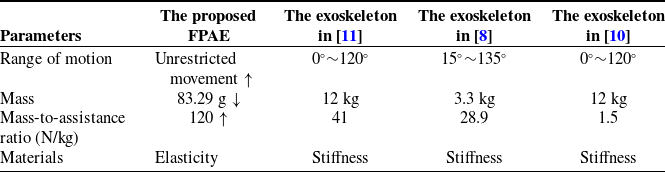
Table I compares the parameters of FPAE with other upper limb exoskeletons in terms of range of motion, mass, mass-to-assistance ratio, and materials. The results indicate that the FPAE has advantages in all four mentioned aspects. It exhibits a broader range of motion compared to others and boasts a lightweight mass of only 83.29 g. With a mass-to-assistance ratio of 120, its assistance effect is more pronounced compared to others. Additionally, the use of elastic materials endows FPAE with excellent comfort. This further highlights its superior assistance efficacy and kinematic adaptability to human movements, enhancing its potential for wider application in the future.
4. Conclusion
This paper introduces the FPAE, a lightweight exoskeleton designed for shoulder support. Weighing just 83.29 g, the FPAE provides a peak assistance force of 10 N, reducing the power output by 8.6 J. In field tests, the maximum additional pressure was only 0.43 N. The heart rate difference before and after using the FPAE is within a range of only 8 bpm. The time taken by five volunteers to complete the motor impairment test varied by less than 0.5 s. In summary, the FPAE demonstrates high adaptability to daily shoulder movements and achieves a satisfaction rate of 93.4% in comfort evaluations. The FPAE introduces a novel mechanical structure and an innovative multimodal comfort evaluation system. This system uniquely integrates distributed pressure measurement, physiological parameter monitoring, and subjective user assessments.
Comparison between the FPAE and similar exoskeletons.

Author contribution
Limin Ren: conceptualization. Enhe Kou: investigation, experiment, writing – original draft. Lirong Jian: investigation. En Jiang: investigation. Xu Zhang: software. Shixun Li: investigation. Huan Zhu: visualization. Shuairan Xu: validation. Yisong Tan: supervision, writing – review & editing.
Financial support
This work was supported by the National Natural Science Foundation of China (No. 52205302), the Natural Science Foundation of Jilin Province (20220101242JC, 20230101321JC), and the Science and Technology Program of the Education Department of Jilin Province (JJKH20230108 KJ, JJKH20230109 KJ). The asterisk indicates the author to whom all correspondence should be directed.
Competing interests
The authors state that they have no financial conflicts of interest or personal relationships that could potentially impact the research presented in this paper.
Ethical approval
All subjects provided informed consent for inclusion before participating in the study. The study was conducted in accordance with the Declaration of Helsinki, and the protocol was approved by the Ethics Committee of Northeast Electric Power University.