




1. Introduction, background, and related work
Backward walking (BW) or backward stepping arises frequently in numerous daily activities, including opening doors, working in a kitchen or at a counter, working in a workshop, and taking photos, to name a few instances. Able-bodied individuals actively flex their knees when walking or stepping backward (Winter et al., Reference Winter, Pluck and Yang1989; Lee et al., Reference Lee, Kim, Son and Kim2013). Doing so has the effect of shortening leg length during swing (similar to forward walking), which increases foot clearance, which in turn increases the margin of safety against stumble events (Chou and Draganich, Reference Chou and Draganich1997; Gailey et al., Reference Gailey, Allen, Castles, Kucharik and Roeder2008; Rosenblatt et al., Reference Rosenblatt, Bauer and Grabiner2017). Although knee flexion can occur passively during forward walking due to inertial coupling between the thigh and shank (i.e., so-called ballistic walking; Mochon and McMahon, Reference Mochon and McMahon1980a, Reference Mochon and McMahon1980b), the same mechanism that provides knee flexion in forward walking imposes knee extension during BW, and therefore does not provide (and even prevents) knee flexion during backward movement. Specifically, during forward walking, forward acceleration of the thigh generates passive knee flexion. During BW, rearward acceleration of the thigh generates passive knee extension. As such, in order to flex the knee during rearward acceleration of the thigh during BW, the knee must generate an (active) torque that overcomes the inertial forces extending the knee, accelerates the knee in flexion, and lifts the foot against gravity. Therefore, in healthy BW, the knee acts as a source of mechanical power rather than dissipating energy as it does through much of forward walking.
Since conventional knee prostheses are energetically passive, they are unable to provide flexion during BW. Instead, users with transfemoral amputation employ a stiff-legged backward step during swing phase, essentially dragging the prosthetic foot backward using hip extension. Users therefore either walk at increased risk of backward stumble (due to lack of foot clearance) or increase foot clearance during BW by employing compensatory movements such as hip hiking and vaulting. While hip compensation is not unique to BW, compensatory actions in general entail known health risks (Kulkarni et al., Reference Kulkarni, Gaine, Buckley, Rankine and Adams2005; Gailey et al., Reference Gailey, Allen, Castles, Kucharik and Roeder2008). Lastly, the stiff-legged motion associated with BW with a conventional knee prosthesis is not symmetric relative to the sound-side movement and therefore aesthetically differentiates a prosthetic knee user from able-bodied individuals.
There are almost no studies exploring means of improving BW in transfemoral amputees. The one study of which the authors are aware demonstrates a powered knee and ankle prosthesis walking backward using the same phase-variable-based control system used for walking forward (Rezazadeh et al., Reference Rezazadeh, Quintero, Divekar, Reznick, Gray and Gregg2019). The authors of that article compare the BW gait to that of a passive prosthesis and demonstrate a much-improved BW step length symmetry index when using the powered device, relative to the passive one. Swing-assist prostheses such as the one used here occupy a middle ground between fully passive and fully powered devices: a small motor can add limited positive work during swing to produce knee flexion that passive devices cannot, while retaining the simplicity, efficiency, and backdrivability of a passive hydraulic knee. The trade-off is that the limited torque is sufficient for shaping swing-phase motion but not for powered stance push-off. Backward walking may be initiated with either the sound or the prosthetic limb. The challenges described here arise specifically during the prosthetic limb’s swing phase, which occurs on every stride regardless of which limb initiates; the controller therefore assists prosthetic-side swing flexion irrespective of the initiating limb. Initiation side affects only the first step and the transition into BW, not the per-stride need for active knee flexion. Swing-phase descriptions throughout this manuscript refer to prosthetic-side swing unless otherwise noted.
In order to help address the general paucity of work on BW, this article proposes a BW controller for a swing-assist knee prosthesis, implements the controller on a swing-assist prosthesis prototype, and examines, in four individuals with transfemoral amputation, the prospective value of the BW controller relative to each participant’s daily-use passive device. We hypothesized that, relative to passive daily-use devices, the swing-assist BW controller would offer knee flexion and extension during backward movement, and that such knee flexion would increase heel clearance and effectively shorten limb length during swing, presumably making walking backward safer and easier. The authors were uncertain about how this assistance would be perceived by the people using it.
2. Methods
2.1. Device description
As previously mentioned, one of the limitations of a conventional energetically passive prosthesis for purposes of BW is the inability to provide swing phase knee flexion, which fundamentally requires the knee to be capable of producing power (i.e., capable of self-generated movement). In order to examine the prospective value of active knee flexion during swing phase in BW, the authors employed a previously described swing-assist knee prosthesis prototype (Lee et al., Reference Lee, Bartlett and Goldfarb2020; Puliti et al., Reference Puliti, Marsh and Goldfarb2024; Marsh et al., Reference Marsh, Puliti and Goldfarb2024a, Reference Marsh, Puliti and Goldfarb2024b) in which to implement a BW controller. This prosthesis, herein called the swing-assist microprocessor-controlled knee (SAMPK), employs a microprocessor-controlled passive hydraulic system to modulate stance and swing phase resistance, similar to other commercially available hydraulic microprocessor-controlled knee prostheses (MPKs). Unlike conventional hydraulic MPKs, however, the SAMPK additionally employs a small, highly backdrivable brushless motor and drive system, such that the knee is capable of self-generated movement, with maximum active torque of approximately 6 Nm at the knee. In this manner, the SAMPK can provide fully passive movements similar to a conventional MPK but can also supplement swing phase movement with limited amounts of active torque when appropriate. As described in (Puliti et al., Reference Puliti, Marsh and Goldfarb2024; Marsh et al., Reference Marsh, Puliti and Goldfarb2024b), in addition to the resistive hydraulic and active assist motor actuation, the SAMPK also includes a six-axis IMU, knee angle encoder, and load cell, which collectively provide information regarding the orientation and angular velocity of the shank and thigh, knee angle and angular velocity, and axial shank load.
2.2. Backward-walking controller
The BW controller implemented in this study is a three-state finite-state-machine controller, as depicted in Figure 1. The three states were constructed around behaviors associated with stance phase, swing flexion, and swing extension. Stance phase support is provided by hydraulic resistance, while swing phase flexion and extension employ low hydraulic resistance assisted by active torques in flexion and extension, respectively. The specific conditions that control movement between states are enumerated in Table 1. The behavior of the knee within each state is as follows. In the stance state (State 1), the flexion valve is closed to elicit high resistance against knee flexion and the motor is de-energized, such that the knee behavior is comparable in function to a conventional MPK in stance phase. Once the user unloads the SAMPK (condition
$ {T}_{12} $
 as measured by the load cell), the controller transitions to the knee flexion state (State 2), in which the flexion valve opens to provide low resistance to knee flexion, and the motor drives flexion with an approximately constant knee torque of 5 Nm (approximately 15 A of motor current) until a (participant-selected) knee angle threshold is met. Upon meeting the desired flexion threshold (or upon a state time-out, included as a safety measure in the case that the threshold knee angle is for some reason not reached), the controller enters the knee extension state (State 3), in which the motor drives knee extension with an approximately constant knee torque of 4 Nm (approximately 12 A of motor current) to extend the knee in advance of loading, while the flexion valve closes to prepare for stance support. In normal BW, the knee returns to the stance state (State 1) upon full knee extension or loading. Note that the state machine also includes a path from swing flexion back to stance (based on loading); as such, regardless of swing state (flexion or extension), if the prosthesis is loaded, the knee will assume a high resistance against flexion.
State machine of the backward-walking controller.

Figure 1. Long description
A flowchart diagram showing three rectangular state boxes connected by directional arrows.
* At the top center is Stance (State 1). The valve has high resistance against flexion and the motor is off.
* To the bottom right is Swing flexion (State 2). The valve has low resistance against flexion and the motor provides flexion torque to drive flexion.
* To the bottom left is Swing extension (State 3). The valve has high resistance against flexion and the motor provides extension torque to drive extension.
Transitions are indicated by arrows:
* T sub 1 2 points from State 1 down to State 2.
* T sub 2 1 points from State 2 up to State 1.
* T sub 2 3 points from State 2 left to State 3.
* T sub 3 1 points from State 3 up to State 1.
Finite state machine transition conditions

Table 1. Long description
A flowchart with three circular nodes representing states, connected by directional arrows representing transitions.
* State 1 is labeled Stand. An arrow labeled T sub 1 2 points from State 1 to State 2.
* State 2 is labeled Swing. Two arrows originate from State 2: arrow T sub 2 1 points back to State 1, and arrow T sub 2 3 points to State 3.
* State 3 is labeled Sit. An arrow labeled T sub 3 1 points from State 3 back to State 1.
According to the associated data table, the transitions are defined as follows:
* T sub 1 2 occurs when the prosthesis is unloaded (F is approximately 0).
* T sub 2 1 occurs when the prosthesis is loaded beyond a threshold (F is greater than F sub t h).
* T sub 2 3 occurs when the knee angle is flexed beyond a threshold (theta sub K is greater than theta sub K comma t h) or a time out occurs (t is greater than t sub t h).
* T sub 3 1 occurs when the prosthesis is loaded (F is greater than F sub t h) or the knee is extended (theta sub K is approximately 0).
Note. Transitions between states depend upon measured sensor inputs and threshold parameters: knee angle (
$ {\theta}_{K,\mathrm{th}} $
 ), shank axial force (
$ {F}_{\mathrm{th}} $
 ), and state time (
$ {t}_{\mathrm{th}} $
 ).
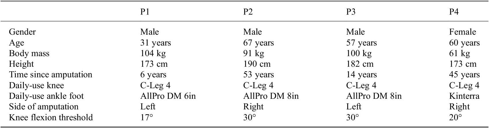
Finally, note that for the thresholds enumerated in Table 1, the axial force threshold was 15% of body weight; the state time threshold was 0.5 s; and the knee angle threshold was participant-selected. Specifically, the knee angle threshold was 17° for P1, 30° for P2, 30° for P3, and 20° for P4. This threshold is participant-dependent because preferred peak swing flexion varied across users with comfort, residual-limb length, and gait strategy; each participant therefore self-selected this threshold during the brief acclimation period described in Section 2.3.
Note that the essential intent of swing control in the backward stepping controller is to add a brief period of knee flexion during swing phase to raise the heel and shorten the leg, which (the authors presume) makes backward stepping safer and easier. A number of different control approaches could be used to impose this brief knee flexion, such as position or impedance control. However, these control approaches can introduce torque reversals in the actuator, which we find that users generally dislike. Although such torque reversals can be eliminated with sufficiently high gains and actuator control authority, they can alternatively be eliminated by employing a smoothed torque pulse, the duration of which is knee-angle limited, essentially to the desired flexion angle. The authors chose to implement this smoothed torque pulse with a time-out, although the time-out is a guard condition for purposes of safety, not the condition that generally terminates the flexion state during backward stepping. The result is movement assistance where the only torque reversal corresponds to a reversal in the desired direction of motion. This approach provides the desired assistance profile with a highly consistent and predictable behavior that avoids the possibility of oscillatory components that might result from a position-based feedback controller. A similar control approach is employed in swing extension, for similar reasons. Regarding the onset of torque commands, the onset is ramped in the torque command to avoid potential user discomfort and is additionally “filtered” by the inertia of the device combined with damping imposed by the hydraulic fluid (i.e., motor torque acts in parallel with the hydraulic system). It should be noted that (based on subjective feedback) users liked the control action and explicitly commented on the predictability of the control action. We believe that predictability is particularly important during BW, when the user generally cannot see the prosthesis. On a related note, although the onset of torque pulses should be comfortable, we believe they should not necessarily be subtle, since a noticeable onset of torque provides feedback to the user regarding actions associated with the powered device. In other words, we want users to feel the onset of swing flexion and to also feel the onset of swing extension (which signals to the user the actions of the knee and, particularly, when it will be ready for loading).
Finally, it should be noted that the knee prosthesis in which the controller was implemented is a low-output-impedance device (during swing phase), so the torque pulse approach also maintains this low output impedance, and therefore maintains a consistency in the “feel” of the device during swing phase. It is also worth noting that the controller as implemented requires very few control parameters, which are the flexion torque magnitude (
$ \sim $
 5 Nm for all participants), extension torque magnitude (
$ \sim $
 4 Nm for all participants), and flexion angle (which is the single parameter selected by participants based on user preference). Note that the flexion and extension torque values were selected empirically during preliminary experimentation as the smallest values that reliably produced the desired swing flexion and extension effects across participants. Although increased controller complexity may eventually be warranted, the controller as described proved to be effective across all trials conducted herein, and experimentation provided no reason to revise it. It should be noted that the experiments described herein constitute an admittedly small subset of potential users and uses; further controller revision may be warranted if further experience with it (e.g., during “real-world” use) reveals a need for improvement.
2.3. Experimental protocol
Experiments were performed, as depicted in Figure 2, assessing gait kinematics during overground BW while using the SAMPK with the BW controller, relative to using each participant’s daily-use MPK. Four individuals with unilateral transfemoral amputation (n = 4) participated in this study. This sample size reflects the proof-of-concept, within-subject design of the study, in which each participant serves as their own control; because no prior effect-size estimates for BW with a swing-assist knee were available, a conventional a priori power analysis was not feasible, and the large within-participant effects observed (Section 3) indicate the design was adequately sensitive. Participant demographics are included in Table 2. The foot/ankle components used by each participant are also listed in Table 2; because the controller acts at the knee, between-participant differences in foot compliance are not expected to materially affect the reported knee kinematics, although they may influence the magnitude of heel clearance.
Backward walking experimental protocol. Four individuals with unilateral transfemoral amputation completed backward walking trials along a straight walkway inside parallel bars. Testing was performed using three prosthetic knee conditions: (a) daily-use MPK; (b) SAMPK with passive controller; and (c) SAMPK with backward-walking controller. Lower-body kinematics were collected using XSENS motion capture markers.

Participant demographics
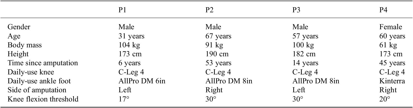
Table 2. Long description
The table consists of five columns. The first column lists the demographic or clinical category, while the subsequent four columns provide data for participants P 1, P 2, P 3, and P 4 respectively.
* Gender: P 1 Male, P 2 Male, P 3 Male, P 4 Female.
* Age: P 1 31 years, P 2 67 years, P 3 57 years, P 4 60 years.
* Body mass: P 1 104 kg, P 2 91 kg, P 3 100 kg, P 4 61 kg.
* Height: P 1 173 cm, P 2 190 cm, P 3 182 cm, P 4 173 cm.
* Time since amputation: P 1 6 years, P 2 53 years, P 3 14 years, P 4 45 years.
* Daily-use knee: All four participants use the C-Leg 4.
* Daily-use ankle foot: P 1 AllPro D M 6in, P 2 AllPro D M 8in, P 3 AllPro D M 8in, P 4 Kinterra.
* Side of amputation: P 1 Left, P 2 Right, P 3 Left, P 4 Right.
* Knee flexion threshold: P 1 17 degrees, P 2 30 degrees, P 3 30 degrees, P 4 20 degrees.
Participants walked backward between parallel bars for stretches of 5 m six times in succession (a total of approximately 30 m). Participants were encouraged not to offload weight onto the handrails. All four participants maintained light contact due to perceived safety concerns during BW. Turns at each end of the parallel bars were exempted from the analysis. Participants repeated the six lengths of BW for three prosthesis cases: 1) on their daily device (which was a C-Leg 4 for all four participants); 2) with the SAMPK without the controller for BW (i.e., with a conventional passive MPK controller); and 3) with the SAMPK with the swing-assist controller for BW. For all cases, kinematics were measured using the commercial motion capture system XSENS Awinda. XSENS IMU markers were placed on top of each foot, mid-shank, mid-thigh, and on the pelvis, making up the default XSENS lower body configuration. In addition to this configuration, four additional IMU markers were placed: right heel, left heel, right hip, and left hip. These markers enabled measurement of standard biomechanical segment data (e.g., joint and link angles), in addition to heel clearance and hip compensatory movements. Prior to each session, the XSENS Awinda system was calibrated using the manufacturer’s standard procedure: each participant stood in a known static neutral pose and performed a short walking calibration, from which sensor-to-segment alignment was computed.
For the BW controller, each participant was given time to acclimate to the controller, during which time each also selected a desired peak knee flexion angle. The process of acclimation and flexion angle selection took no more than 15 min for each. Finally, each participant was given a subjective feedback questionnaire for each of the three conditions. Experiments were conducted with the approval of Vanderbilt University’s Institutional Review Board (IRB), under IRB#110667.
2.4. Statistical analysis
All statistical comparisons were performed within each participant. Participant data were not pooled for group-level comparison nor compared between participants. All analyses were performed on per-stride variables. For each participant, statistical comparisons were pairwise (daily device vs. SAMPK passive, daily device vs. SAMPK with BW controller, and SAMPK passive vs. SAMPK with BW controller where relevant) using the Mann–Whitney U test (Wilcoxon rank-sum test). Mann–Whitney was chosen as stride-level distributions were not assumed to be Gaussian and may have unequal variances and sample sizes. There is additionally no pairing of strides across conditions. To control the family-wise error rate for the multiple condition comparisons within a participant, Holm–Bonferroni correction (m = 3) was applied to the set of p-values from the pairwise tests.
Heel clearance was computed from the vertical position of the heel marker during swing and summarized over the middle 80% of the normalized step (10–90%) to minimize the influence of gait initiation and termination. To compare heel-height profiles across strides of differing length, each profile was parameterized by normalized heel-travel distance u – the cumulative spatial displacement of the heel between successive heel contacts – rather than by time. Distance-based normalization keeps u monotonic even when the heel momentarily advances forward during a backward step, allowing a one-to-one mapping of heel height versus position and enabling computation of the area under the curve.
3. Results
Data from the trials are shown in Figures 3–8 and Tables 3–6. A video corresponding to these data (i.e., each participant walking with each device case) is included with the Supplementary Material submitted with this article. The results are divided below into results associated with knee angle, heel clearance, hip compensation, and subjective impressions.
SAMPK backward-walking control shifts peak knee flexion to swing phase.

Figure 3. Long description
The figure consists of eight line graphs organized into four rows (P 1, P 2, P 3, P 4) and two columns (Daily Device on the left, S A M P K B W Control on the right).
Common Axes and Legend:
* The Y-axis represents Knee Angle in degrees, ranging from 0 to 40.
* The X-axis represents Time in seconds, ranging from 0 to 2.
* A legend in the top-left panel identifies an orange circle as Peak Knee Angle (Swing), a blue line as Knee Angle, and gray shaded regions as Stance Phase.
Data Trends:
* Left Column (Daily Device): For all participants (P 1 through P 4), the blue knee angle line shows low-amplitude peaks. The orange circles (peak knee angle) are located within or at the edge of the gray shaded stance phases, indicating peak flexion occurs during stance.
* Right Column (S A M P K B W Control): For all participants, the blue line shows significantly higher, sharper peaks reaching between 20 and 35 degrees. Crucially, the orange circles are now positioned in the white unshaded regions, indicating that peak knee flexion has shifted to the swing phase.
* Participant Specifics: P 2 and P 3 show the most dramatic increase in peak height when switching from the Daily Device to the S A M P K B W Control.
Participants’ peak knee angle by condition. Boxplots show peak knee flexion during the swing phase of backward walking for four participants and three conditions: daily C-Leg (pink), SAMPK passive (orange), and SAMPK BW control (green). Asterisks denote significance (***p < .001). All participants demonstrated higher peak knee angle with the backward-walking controller relative to both daily-use and SAMPK passive conditions.

Figure 4. Long description
The vertical y-axis is labeled Peak Knee Angle in degrees, ranging from 0 to 45. The horizontal x-axis identifies four participants as P 1, P 2, P 3, and P 4. A legend at the top left identifies three conditions: Daily C-Leg in pink, S A M P K Passive in orange, and S A M P K B W Control in green.
For each participant, three boxplots are clustered together. In all four cases, the green S A M P K B W Control boxplot shows a significantly higher peak knee angle compared to the other two conditions.
* For P 1: Pink is at approximately 15 degrees, orange at 8, and green at 18.
* For P 2: Pink is very low at 4 degrees, orange at 6, and green at 30.
* For P 3: Pink is at 4 degrees, orange at 7, and green at 28.
* For P 4: Pink is at 8 degrees, orange at 5, and green at 23.
Statistical significance brackets with triple asterisks are positioned above the boxplots for each participant, indicating p less than .001 when comparing the B W Control to the other two conditions. Outliers are represented by small circles, notably below the green box for P 2 and P 4.
BW knee angle trajectories including sound side. Solid lines indicate stance phase, and dashed lines indicate swing phase. Percent gait cycle spans toe contact (0%) through stance and swing to the subsequent toe contact (100%). The able-bodied healthy reference trajectory is included for biomechanical context and was adapted from Lee et al. (Reference Lee, Kim, Son and Kim2013).

Figure 5. Long description
A five-panel line graph. The horizontal x-axis for all panels is Percent Gait (%) from 0 to 100. The vertical y-axis is Knee Angle (deg) from 0 to 50.
* The first panel, Healthy B W, shows a solid black line with a grey shaded variance band. It features a small peak around 30 percent gait and a large peak of approximately 47 degrees at 70 percent gait.
* Panels 2 through 5 are labeled P 1, P 2, P 3, and P 4. Each contains four trajectories: Daily (C-Leg) in purple, S A M P K Passive in red, S A M P K B W Control in green, and Sound Side in grey. Solid lines represent the stance phase and dashed lines represent the swing phase. Open circles mark the Swing Peak for each mode.
* In P 1, the Sound Side peak is highest at 38 degrees. The S A M P K B W Control peak is lowest at 18 degrees.
* In P 2, the Sound Side peak is at 40 degrees. The S A M P K B W Control peak reaches 28 degrees, while Daily and Passive modes remain below 10 degrees.
* In P 3, the Sound Side peak is the highest in the set at 52 degrees. S A M P K B W Control reaches 28 degrees.
* In P 4, the Sound Side peak is at 48 degrees. S A M P K B W Control reaches 26 degrees.
* Across all participant panels, the S A M P K B W Control (green) consistently produces a higher swing phase knee angle than the Daily or Passive modes, though it remains lower than the Sound Side and Healthy B W reference.
Average heel trajectories per stride. Mean per-participant heel-height profiles for each condition, plotted against normalized heel-travel distance u (defined in Section 2.4). The horizontal axis runs from one heel contact (0) to the next (1).

Figure 6. Long description
The four panels are stacked vertically. Each panel shares a common horizontal axis labeled u along Delta X (Heel-Based) ranging from 0 to 1. The vertical axis is Heel Clearance in centimeters, with scales varying between 0 to 8 and 0 to 15.
Legend in the top-left panel identifies three conditions:
- Daily (C-Leg) in pink.
- S A M P K Passive in orange.
- S A M P K B W Control in green.
Each line is accompanied by a shaded region representing variance.
- Panel P 1: The green line rises steadily to a peak of approximately 5 centimeters at u equals 0.9. Pink and orange lines remain lower and nearly identical, peaking around 3 centimeters.
- Panel P 2: The green line shows a broad arc peaking at 5 centimeters near u equals 0.6. Pink and orange lines are flatter, staying below 2.5 centimeters.
- Panel P 3: All lines remain low until u equals 0.5. The green line then climbs sharply to a peak of nearly 10 centimeters at u equals 0.9. The orange line follows a similar but lower curve peaking at 7 centimeters, while the pink line remains flat.
- Panel P 4: The green line maintains the highest clearance throughout, peaking at 9 centimeters near u equals 0.85. Pink and orange lines track closely together, peaking near 5 centimeters.
Heel clearance over the middle 80% of stride by condition. Boxplot shows median heel clearance (cm) over the middle 80% of stride for each participant across three knee conditions: daily C-Leg (pink), SAMPK passive (orange), and SAMPK BW control (green). Asterisks denote significance (***p < .001). All participants demonstrated higher heel clearance with the backward-walking controller relative to both daily-use and SAMPK passive conditions.

Figure 7. Long description
A boxplot graph titled Heel Clearance (Per-Stride, Absolute Distance).
* The Y-axis is labeled Median Heel Clearance (cm) Over 10-90 percent of Delta X, with a scale from 0 to 10.
* The X-axis identifies four participants: P 1, P 2, P 3, and P 4.
* A legend in the top-left corner identifies three conditions: Daily (C-Leg) in pink, S A M P K Passive in orange, and S A M P K B W Control in green.
Data Trends:
* For all participants, the green S A M P K B W Control boxplots are positioned significantly higher than the other two conditions, with medians ranging from approximately 4 cm (P 1 and P 2) to nearly 6 cm (P 4).
* The pink Daily (C-Leg) and orange S A M P K Passive conditions show lower clearance, generally between 1.5 cm and 4 cm.
* Statistical significance brackets with triple asterisks (indicating p < .001) are placed above the groups, specifically comparing the B W Control to both the Daily and Passive conditions for every participant.
* P 4 shows the greatest variance in the B W Control condition, with whiskers extending from approximately 2 cm to nearly 10 cm.
Hip compensation by condition and participant. Boxplots show vertical hip hiking amplitude (per-stride peak-to-trough displacement of the prosthetic-side hip XSENS marker) during backward walking for four participants and three conditions: daily device (C-Leg), SAMPK passive, and SAMPK BW control. Asterisks denote significance (*
$ p<.05 $
 , **
$ p<.01 $
 , ***
$ p<.001 $
 ; n.s., not significant).

Figure 8. Long description
The y-axis represents Hip Compensation in centimeters ranging from 0 to 9. The x-axis is categorized by four participants labeled P 1, P 2, P 3, and P 4. For each participant, three colored boxplots are shown: pink for Daily C-Dash Leg, orange for S A M P K Passive, and green for S A M P K B W Control.
* P 1: Daily shows the highest median near 6 centimeters. S A M P K Passive and Control show lower medians around 5 and 4.5 centimeters respectively. Significant differences are marked between Daily and Control (three asterisks) and Passive and Control (one asterisk).
* P 2: All values are lower, between 2 and 4 centimeters. Daily is significantly higher than Passive (one asterisk), while Passive and Control are not significant (n.s.).
* P 3: Daily and Passive have similar medians around 4.5 centimeters, both significantly higher than Control (three and two asterisks respectively).
* P 4: Daily has the highest median near 4.5 centimeters. Passive is significantly lower than both Daily (one asterisk) and Control (three asterisks).
Statistical significance brackets are positioned above the boxplots for each participant group.
Median peak knee angle (°) of participants by condition

Table 3. Long description
The table consists of five columns and four rows. The header row lists the Condition followed by participants P 1, P 2, P 3, and P 4. Values are reported as median with the first and third quartiles in brackets and the sample size n in parentheses.
* Daily condition: P 1 is 14.5 [12.6, 17.2] (n = 34); P 2 is 3.9 [3.4, 4.1] (n = 38); P 3 is 4.3 [3.6, 5.1] (n = 32); P 4 is 8.8 [6.7, 11.4] (n = 29).
* S A M P K passive condition: P 1 is 8.6 [6.2, 11.0] (n = 30); P 2 is 6.1 [4.9, 7.5] (n = 58); P 3 is 6.7 [4.3, 7.6] (n = 23); P 4 is 4.7 [3.0, 7.1] (n = 27).
* S A M P K B W condition: P 1 is 17.7 [17.0, 18.7] (n = 38); P 2 is 30.0 [26.5, 31.1] (n = 62); P 3 is 28.7 [27.2, 30.1] (n = 31); P 4 is 23.4 [22.3, 24.7] (n = 30).
Note. Values reported as median [Q1, Q3] (n).
Median heel clearance (cm) during swing phase by condition

Table 4. Long description
The table consists of five columns and four rows. The header row lists the Condition followed by participants P 1, P 2, P 3, and P 4. Data values are presented as median followed by the first and third quartiles in brackets and the sample size n in parentheses.
* Row 1, Daily condition: P 1 is 2.40 [2.17, 2.82] (n = 34); P 2 is 2.24 [2.00, 2.38] (n = 38); P 3 is 2.99 [2.72, 3.30] (n = 32); P 4 is 3.31 [3.10, 3.80] (n = 29).
* Row 2, S A M P K passive condition: P 1 is 2.45 [1.80, 3.07] (n = 30); P 2 is 1.62 [1.52, 1.88] (n = 58); P 3 is 3.75 [3.21, 4.44] (n = 23); P 4 is 2.71 [2.49, 3.08] (n = 27).
* Row 3, S A M P K B W condition: P 1 is 3.78 [3.46, 4.09] (n = 38); P 2 is 4.14 [3.77, 4.45] (n = 62); P 3 is 4.85 [4.16, 5.60] (n = 31); P 4 is 5.78 [5.05, 7.11] (n = 30).
Note. Values reported as median [Q1, Q3] (n). Computation is described in Section 2.4.
Hip compensation (cm) by condition

Table 5. Long description
The table consists of five columns and four rows. The header row lists the Condition followed by participants P 1, P 2, P 3, and P 4. Values are reported as median with the first and third quartiles in brackets and the sample size n in parentheses.
* Daily condition: P 1 is 5.8 [4.8, 6.7] n = 34; P 2 is 2.9 [2.5, 3.4] n = 38; P 3 is 4.5 [4.0, 4.9] n = 32; P 4 is 4.7 [4.0, 5.2] n = 29.
* S A M P K passive condition: P 1 is 4.8 [3.9, 5.6] n = 30; P 2 is 2.6 [2.1, 3.0] n = 58; P 3 is 4.4 [4.2, 5.1] n = 23; P 4 is 3.5 [3.1, 3.7] n = 27.
* S A M P K B W condition: P 1 is 4.3 [3.6, 4.7] n = 38; P 2 is 2.5 [2.1, 3.0] n = 62; P 3 is 3.8 [3.2, 4.1] n = 31; P 4 is 4.1 [3.8, 4.7] n = 30.
Note. Values reported as median [Q1, Q3] (n).
Participants’ subjective feedback across conditions

Table 6. Long description
The table presents qualitative data for four participants (P 1, P 2, P 3, P 4) across three device conditions: Daily (C-Leg 4), S A M P K passive, and S A M P K B W.
1. Knee responsiveness:
- P 1: Neutral (Daily), High (Passive), Very high (B W).
- P 2: Very low (Daily), Very low (Passive), High (B W).
- P 3: Neutral (Daily), Very low (Passive), Neutral (B W).
- P 4: Neutral (Daily), High (Passive), Very high (B W).
2. Foot clearance confidence:
- P 1: Low (Daily), High (Passive), High (B W).
- P 2: High (Daily), High (Passive), Very high (B W).
- P 3: Very high (Daily), Very high (Passive), Very high (B W).
- P 4: High (Daily), Very high (Passive), Very high (B W).
3. Perceived hip effort:
- P 1: High (Daily), Neutral (Passive), Low (B W).
- P 2: High (Daily), High (Passive), Neutral (B W).
- P 3: Neutral (Daily), High (Passive), Low (B W).
- P 4: Low (Daily), Very low (Passive), Very low (B W).
Note: Responses are based on a five-point Likert scale ranging from very low to very high.
Note. Responses are shown on a five-point Likert scale (very low, low, neutral, high, very high). Dark green indicates the most desirable response and red indicates the least desirable response.
3.1. Knee angle
Figure 3 shows representative data from the BW trials of each participant for testing conditions corresponding to each participant’s daily-use passive device (i.e., C-Leg 4) and to the SAMPK with BW controller. Specifically, each plot shows knee angle versus time for two representative BW strides, where the gray bands indicate stance phase and white bands indicate swing phase. The peak knee angle during swing phase is indicated for each stride by a red marker on the knee angle trace.
Consider first BW with the daily-use passive prostheses (all C-Leg 4 prostheses), which is the first column of the figure. One can observe that participants P1 and P4 walked quite differently from P2 and P3, and thus had substantially different knee angle patterns. In particular, participants P2 and P3 both employed a generally “stiff-legged” gait with the passive prosthesis, with essentially no knee flexion during the stance phase and roughly 5° during the swing phase. Participants P1 and P4, conversely, incurred substantial knee flexion during the stance phase as the prosthesis was weighted, followed by knee extension during swing phase as the prosthesis was unweighted (somewhat similar to prosthetic knee behavior observed during downslope forward walking). This stance-phase flexion of roughly 17° and 8.8° in P1 and P4 reflects a weight-activated knee-yielding strategy with the C-Leg (in which stance flexion is engaged under load) and is not an artifact of the IMU-based motion capture: the same offset appeared consistently across all strides, and in the SAMPK conditions it was further verified by the on-board knee encoder. Because P1 and P4 achieve maximum flexion in late stance, the peak knee angle during swing phase occurs at the instant the prosthesis is unloaded (as indicated by the red markers), since the remainder of swing phase is characterized entirely by knee extension. Participants P2 and P3 have peak swing knee angles later in swing phase, although the knee remains largely extended for the entirety of the walking cycle (i.e., thus the label of “stiff-legged” gait).
Consider now the data corresponding to BW with the SAMPK with BW controller (i.e., the second column of the figure). One can observe that the gait patterns of all four participants look considerably more similar than when using the passive devices, although P1 and P4 still incur some amount of knee flexion during stance phase, while P2 and P3 generally maintain an extended knee during stance phase. In all cases, when walking with the SAMPK with BW controller, swing phase is characterized by an initial flexion and subsequent extension movement, similar to the movement employed in healthy BW, with peak knee angle in swing phase corresponding to the desired knee angle threshold employed in the BW controller, and indicated in the figure with the red markers. Note that the video submitted with this article provides useful context within which to interpret the movement corresponding to each plot in Figure 3.
Figure 4 shows the median swing phase peak knee angles (i.e., as represented by the red markers on the plots in Figure 3), and interquartile (IQR) ranges for all steps taken during the experimental protocol. Recall that each case entailed approximately 30 m of BW. In addition to the daily-use and SAMPK with BW controller conditions shown in Figure 3, the data shown in Figure 4 also includes the third experimental condition of using the SAMPK with a conventional passive walking controller (i.e., without the BW controller), which was expected to provide behavior generally matching that of the daily-use MPK (an expectation which is in fact validated by the data). P2 elected to walk somewhat more in the SAMPK trials (
$ \sim $
 40m passive,
$ \sim $
 50m BW); these data were retained as they were indistinguishable from the first 30 m and modestly reduced variance. Each condition averaged 36 steps per participant (minimum 23; all others greater than 27). The median and IQR corresponding to each case, and the number of data points corresponding to each case, are enumerated for each participant in Table 3. As evident in Figure 4 and Table 3, the SAMPK with BW controller resulted in significantly greater swing phase peak knee angles during BW, compared with both the daily-use device and the SAMPK without BW controller.
Figure 5 shows the knee angle versus stride for a typical stride of BW for each participant for each of the three device cases and also for each participant’s sound side, where 0 and 100% correspond to toe contact (i.e., transition from swing to stance). The sound side knee angle trajectory shown for each participant was taken from the SAMPK BW control trial. For P2, P3, and P4, the sound sides from all trials were of similar magnitude and phase, so the sound trajectories shown are representative across all trials. For P1, both SAMPK trials (passive and BW control) were comparable, although the sound knee angle for the daily-use case was lower in magnitude than the case shown in Figure 5. For all participants, the SAMPK with BW controller provided substantially improved knee angle symmetry, relative to the passive cases, for both the strategy of P1/P4 and the strategy of P2/P3. Notably, for the cases on P2 and P3, the SAMPK BW control increased the magnitude of peak knee angle during swing phase, thus more closely mirroring the healthy side. In the case of P1 (who employed a stance-phase knee-yielding strategy), the SAMPK BW control case moved the peak knee angle to the swing phase, as is reflective of healthy movement. For P4, the SAMPK BW control case achieved both a higher magnitude peak knee angle and shifted the peak from stance to swing phase. In all four cases, SAMPK BW control fostered a much more symmetric gait than when using either passive device.
3.2. Heel clearance
During BW, the heel is the leading edge of the foot and is therefore the portion of the foot most likely to catch on an irregularity in the ground during backward swing; the heel is therefore the clearance most relevant to backward-stumble risk. Other parts of the foot may contact the ground during BW (just as the heel may contact the ground during forward walking), but such contact is likely to result in a scuffing perturbation, which is less severe than a stumble perturbation that abruptly stops foot motion and requires elevation to overcome. As such, we focus here on stumble, which is most directly related to heel clearance during BW.
Figure 6 shows the mean heel-trajectory profiles for each participant for each testing condition. As shown in the figure, the SAMPK BW control increased the mean heel clearance across most of swing for all participants. For P1, P2, and P4, heel clearance for the BW controller case exceeds both passive cases throughout mid-to-late swing; for P3, heel clearance with the BW control is similar to the passive devices during early swing but increases substantially relative to them after approximately 45% swing.
Figure 7 summarizes heel clearance data for all participants and all trials, specifically indicating the average heel clearance during the middle 80% of the normalized step length (i.e., from 10 to 90% of the normalized step length in Figure 6). The median and IQR for each case are enumerated in Table 4. In aggregate, the mean heel clearance across participants was 2.76 cm for the daily-use case and 4.72 cm for the SAMPK with BW controller case, an increase of about 1.96 cm.
3.3. Hip compensation
Hip motion was measured to assess the extent to which participants might be employing hip elevation (i.e., hip hiking) to affect heel clearance for a given device case (i.e., increasing prosthetic-side hip elevation during swing phase would increase heel clearance). As such, the vertical motion of the prosthetic-side hip was measured, and the extent of hip compensation was quantified as the peak-to-peak amplitude of hip vertical motion per stride (i.e., difference in maximum and minimum of the prosthetic side hip marker in the vertical direction). This measurement should capture the net effect of compensatory action from the unaffected side (i.e., ankle, knee, hip), although it would not capture potential circumduction on the prosthetic side. The authors note, however, that no such prosthetic-side circumduction was observed.
The (prosthetic-side) hip elevation is summarized for each participant and device case in Figure 8 and Table 5. Across participants, median hip compensation was lower when using the SAMPK with BW controller than when using either passive device case (with the exception of P2 and P4 using the SAMPK in passive mode). On average, the vertical hip motion was 4.37 cm when using daily-use devices and 3.46 cm when using the SAMPK with BW controller. Therefore, the improved heel clearance observed when using the SAMPK with BW controller, evident in Figures 6 and 7, was achieved with decreased hip compensation, relative to the daily-use devices.
3.4. Subjective feedback
Participants provided subjective ratings of their BW experience across the three conditions with Likert-style responses (very low, low, neutral, high, very high). Questions targeted knee responsiveness, foot clearance confidence, and perceived hip effort. These questions were chosen to align with quantitative measures of knee angle, heel clearance, and hip compensation. A summary of responses is provided in Table 6, where the five responses are color-coded, and where dark green shading corresponds to the most desirable outcome, and where dark red corresponds to the least desirable for each of the subjective questions. For knee responsiveness, P1, P2, and P4 reported increases between the SAMPK BW controller and their daily device. For foot clearance confidence, P1, P2, and P4 showed improvements, increasing from low (P1, daily device) and high (P2/P4, daily device) to high and very high, respectively, with the controller. P3 consistently reported very high confidence across all conditions, including with the SAMPK BW controller. For perceived hip effort, P1, P2, and P3 reported reductions with the controller compared to both the SAMPK passive and daily device conditions. P4 reported reductions with the controller compared to their daily device. P1 shifted from high effort with his daily device to low effort with the controller. P2 reported high effort with both daily and SAMPK passive conditions, which decreased to neutral with the controller. P3 shifted from neutral with his daily device to low with the controller; P4 shifted from low to very low. Overall, subjective feedback was consistent with objectively measured outcomes, with participants reporting improved knee responsiveness, greater confidence in foot clearance, and reduced hip effort when walking backward with the SAMPK BW controller.
4. Discussion
To our knowledge, this is the first exploration of a BW controller for a swing-assist knee prosthesis, and the first demonstration that movement-specific swing assistance can provide swing-phase knee flexion, increase heel clearance, and reduce hip compensation during BW in people with transfemoral amputation. These results establish BW as a distinct, addressable activity mode and provide a practical, low-torque control approach that could be incorporated into other swing-assisted knee prostheses.
The findings of this study demonstrate that implementing a BW controller on a prototype semi-powered prosthetic knee alters gait compared to both the participants’ daily microprocessor knee (C-Leg 4) and the prototype in a passive mode. While differences were observed between the daily and passive SAMPK conditions (likely reflecting the higher stance flexion resistance of the passive SAMPK), the most pronounced biomechanical and perceptual improvements were attributed to the BW controller.
4.1. Knee flexion and swing dynamics
With the BW controller, peak knee flexion consistently occurred in the mid-swing phase (consistent with healthy movement) and increased in magnitude across all participants. This contrasts with the daily and SAMPK passive conditions, which often exhibited stance knee yielding or no significant knee flexion during swing. It is important to note here that the goal of the BW controller was not to replicate the stance-phase behavior of the sound limb, since many users prefer to land with a fully extended prosthetic knee for perceived stability and safety. Instead, the objective was to more closely emulate the swing-phase characteristics of the healthy limb, particularly knee flexion timing and magnitude, while maintaining a high stance resistance to support the user’s preferred landing behavior. By assisting flexion and extension in swing and allowing participants to self-select their desired peak knee angle, the controller successfully facilitated a more biomimetic swing trajectory. Participants 2 and 3, who chose higher flexion peak knee angles than Participants 1 and 4, demonstrated correspondingly larger peak knee flexion. Greater swing-phase flexion shortened the limb and reduced the reliance on clearance strategies such as hip hiking or other compensations. The correlation between higher peak knee flexion and lower hip excursion suggests that the controller directly reduced compensatory behaviors.
4.2. Heel clearance
The controller consistently increased heel clearance across swing for all participants, with median heel height significantly greater in the BW condition. In forward walking, even small improvements in clearance (
$ \sim $
 1.3 cm) are considered clinically meaningful for reducing stumble risk (Rosenblatt et al., Reference Rosenblatt, Bauer and Grabiner2017). The improvement observed in this work is above 1.3 cm, implying a reduction in tripping risk during BW maneuvers. This finding is particularly relevant for short, reactive steps, where BW safety is paramount.
4.3. Hip compensation
Reductions in vertical hip excursion were observed in all participants when walking with the BW controller, relative to daily-use devices. This measured decrease in hip compensation was corroborated by subjective reports of reduced hip effort. Since long-term reliance on asymmetric hip and pelvic compensations, such as hip hiking and anterior pelvic tilt, has been suggested to increase lumbopelvic loading and contribute to low back pain in people with lower limb amputation (Devan et al., Reference Devan, Hendrick, Ribeiro, Hale and Carman2014), reductions in these compensations suggest the controller could potentially mitigate musculoskeletal burden.
4.4. Subjective impressions
Subjective ratings tracked the biomechanical findings: participants reported greater knee responsiveness, higher foot-clearance confidence, and reduced hip effort with the BW controller (Section 3.4).
4.5. Gait symmetry
By shifting knee flexion into swing, reducing stance yielding, and promoting more symmetric phasing relative to the sound limb, the BW controller produced gait patterns more consistent with healthy biomechanics (see Supplementary Video submitted with this article). Finally, these improvements occurred without full actuation, highlighting that semi-powered assistive devices like the SAMPK can achieve meaningful functional benefits with relatively low active torque.
4.6. Integration within an activity-mode control framework
The experiments presented here were intended to examine the extent to which there might be prospective value in a BW controller. Prior to conducting these experiments, at least one author of this article (incorrectly) predicted that users would not like the feeling of swing flexion in BW. That was not the case for the users in this article, who liked the active assistance given to them. The controller presented here would be implemented within a finite-state framework of activity controllers that includes at least forward walking. Although such a framework is not the topic of this article, including a BW activity mode within a forward walking activity mode framework would likely switch into BW based on the sign of walking velocity, information which is available to the prosthesis during each stance phase (based on measurements from the IMU and knee encoder). Using this information to switch into a BW activity mode would constrain the user to initiating a backward step with the unaffected leg. In the case that a user were to initiate BW with the prosthesis, the initial step would not incorporate swing assistance, and rather would behave as a typical MPK in BW (i.e., would be stiff-legged motion). If there was an explicit user-triggered signal, the BW controller could engage even for prosthetic-side initiation.
4.7. Clinical implications
This work highlights three clinically relevant changes enabled by the BW controller. First, by increasing stance-phase resistance during BW, the controller decreased knee yielding during stance, enabling more efficient backward push-off with reduced stance flexion. Second, the controller restored peak flexion to occur during mid-swing, which shortens the limb and provides higher clearance or margin of safety over ground irregularities, reducing the likelihood of a stumble. Third, use of the BW controller lowered changes in hip elevation, which may reduce long-term musculoskeletal burden as well as momentary effort and discomfort.
For clinical practice, these outcomes translate to safer mobility with less effort. Safer, more efficient backward stepping may reduce near-falls, decrease fatigue, and increase participation in daily activities. Importantly, some of the benefits observed here do not require a fully powered device. Commercial microprocessor knees could incorporate increased stance flexion resistance to mitigate knee yielding during BW; P1, for example, clearly preferred this behavior. In this study, participants adjusted and acclimated to the BW controller within 15 min, suggesting that prosthetists could feasibly tailor these parameters in a standard fitting session and that users can quickly realize the benefits of the controller.
Broader adoption could yield downstream benefits for patients, providers, and payers (owing to fewer falls, less secondary pain, and reduced utilization of healthcare), although a formal health-economic analysis would be needed to substantiate these.
4.8. Limitations
This study uses a small sample size of four (male n = 3, female n = 1), unilateral transfemoral amputees using the C-Leg 4 as their daily device. Generalization to other demographics, activity levels, and other commercial knees is unknown. We therefore present this work as a proof-of-concept case series rather than a powered group study; although the four participants already displayed distinctly different BW strategies, a larger and more diverse cohort is needed to establish generality, and we hope to pursue this in future work. The acclimation time to the controller was short, and the overall testing lasted under 3 hr per participant. Benefits may increase with training and familiarity with the actions of the controller. On the other hand, some improvement, for example hip compensation reductions, could reflect short-term novelty or other effects. The protocol was not randomized due to safety concerns (BW is uncomfortable and does not feel safe for most knee prosthesis users, including the users we tested). BW was performed between parallel bars over approximately 5 m stretches, excluding turns. Real-world surfaces, obstacles, and the absence of handrails may alter performance and perceived safety when using the controller. While users were instructed to walk at the same speed for each trial, walking speed during BW was not directly controlled nor reported; differences in speed may influence peak knee flexion and other kinematics. More fundamentally, the controller does not explicitly adapt to walking speed: the assist torques and transition thresholds are fixed, so it is not clear how the controller or prosthesis accommodates BW at cadences substantially faster or slower than those tested here. The extent to which this is a practical limitation is unclear (i.e., to what extent does this controller accommodate different BW speeds and to what extent do people with amputation require or desire different BW speeds). Finally, regarding data collected using the XSENS systems, it should be noted that, while well-validated (Lordall et al., Reference Lordall, Mehrabani, Bui, Oates and Lanovaz2025), kinematics from the XSENS IMU system can drift or differ from camera-based motion capture systems.
5. Conclusion
This article proposes a BW controller that employs swing assistance with the intent of improving BW movement. In particular, the BW controller was implemented on a swing-assist knee prosthesis prototype to provide powered flexion and extension assistance during swing phase, in addition to increased resistance during stance phase, relative to standard MPK devices. In experiments with four users with transfemoral amputation, the swing-assist device with BW controller provided increased peak knee flexion in swing phase; improved gait symmetry; greater heel clearance; and lowered vertical hip excursion, all relative to daily-use passive MPKs. Clinically, the combination of greater BW symmetry, greater heel clearance, and reduced compensation at the pelvis suggests a greater margin of safety and a lower physiological burden for users who engage in BW maneuvers. While the study is limited by small sample size and a brief acclimation period, it provides a compelling proof of concept that movement-specific BW control can change lower-body kinematics in a way that matters to users.
Supplementary material
The supplementary material for this article can be found at http://doi.org/10.1017/wtc.2026.10048.
Data availability statement
To support future studies and benchmarking on backward walking (an area with little prior data), the processed biomechanics data and main scripts from this study are available at doi:10.5281/zenodo.21144535. Any other data can be made available to interested researchers upon request by email to the corresponding author.
Authorship contribution
M.H., D.M., and M.G. conceived and designed the study. M.H. and D.M. conducted data gathering. M.H. performed statistical analyses. M.H. and M.G. wrote the article.
Funding statement
This research received no specific grant from any funding agency in the public, commercial, or not-for-profit sectors.
Competing interests
The authors declare no competing interests exist.
Ethical standards
All experimental protocols were approved by the Vanderbilt Institutional Review Board, and all participants gave their written informed consent.










 Open access

