1. Introduction
Due to traffic accidents, natural disasters, industrial injuries, and diseases, a large number of people worldwide suffer from lower limb amputation or lower limb dysfunction each year [Reference Bhuiyan, Choudhury and Dahari1]. Loss of lower limb function leads to the loss of walking ability and seriously affects patients’ daily life and independent mobility. Owing to current limitations in medical technology, lower limb function is difficult to restore naturally [Reference Highsmith, Kahle, Miro, Orendurff, Lewandowski, Orriola, Sutton and Ertl2]. Therefore, lower limb prostheses, exoskeletons, and lower limb assistive robots have become important technical approaches for restoring walking ability.
Semi-active control devices based on magnetorheological fluid (MRF) have been widely applied in various lower limb assistive devices because of their fast response and continuously adjustable damping characteristics [Reference Dutra, de Andrade, Soares, Thakor and Vimieiro3, Reference Zhou, Liu, Han, Li, Zhang and Liu4]. In prosthetic systems for lower limb amputees, magnetorheological technology has mainly been used for damping regulation in knee and ankle joints, including low-cost prosthetic knees [Reference Qadir, Haq, Khan, Shah, Chouikhi and Ismail5], controllable ankle–foot prostheses [Reference Negi, Sagar, Nautiyal and Sharma6], and optimized MR dampers for prosthetic ankle joints [Reference Kumar, Chandramohan and Sujatha7–Reference Kumar, Reddy and Chandramohan10]. In assistive exoskeletons, MR dampers and MR actuators have been used to provide adjustable joint support and damping control [Reference Khazoom, Veronneau, Bigue, Grenier, Girard and Plante11, Reference Shi, Lin, Nie, Zhao, Bai, Wu, Liao and Gao12]. In lower-limb robotic and rehabilitation systems, MR-based actuation units have also been applied to knee and ankle joint mechanisms to achieve compliant control and personalized rehabilitation assistance [Reference Kikuchi, Oda, Yamaguchi and Furusho13, Reference Xu, Li, Xu, Peng, Chen, Liu, Xu, Cheng, Xu, Liu and Chen14]. These studies demonstrate the good application potential of magnetorheological technology in knee and ankle joints.
Among lower limb prosthetic joints, the knee joint is the most critical one because it bears high loads and performs complex motions during lower limb movement. In the structural design of magnetorheological prosthetic knee joints, the combination of a single-axis structure and an MR damper has been widely adopted [Reference Carlson, Matthis, Toscano and McGowan15–Reference Saini, Kumar and Chandramohan22]. Carlson et al. [Reference Carlson, Matthis, Toscano and McGowan15], Kim et al. [Reference Kim and Oh16], and Herr et al. [Reference Herr and Wilkenfeld17, Reference Herr, Wilkenfeld and Bleck18] developed MR-damper-based prosthetic knee designs for trajectory tracking and damping control. Zuo et al. [Reference Zuo, Zhao, Mei, Yi and Hu19] further proposed a robust control method to improve swing phase trajectory tracking. To satisfy the walking requirements of semi-active prosthetic knee joints, Fu et al. [Reference Fu, Wang, Xu and Yuan20], Song et al. [Reference Song, Cao, Chen, Ren, Ma, Wang, Wang, Zhang and Ren21], and Saini et al. [Reference Saini, Kumar and Chandramohan22] optimized the structure and parameters of MR dampers. Related MR-based knee joint designs have also been extended to exoskeleton applications [Reference Song, Zhang, Chen, Ju, Kang and Dai23–Reference Do, Mai, Kang and Choi25]. Although these studies have made progress in structural design and control methods, some limitations still remain. On the one hand, the rotational form of single-axis prosthetic knee joints is too simple to mimic the variation of the instantaneous center of rotation of the human knee. On the other hand, MR dampers are semi-active actuators and cannot provide active torque, which limits their performance in uphill walking and obstacle-crossing conditions.
In fact, flexion and extension of the human knee do not occur about a fixed axis. Instead, they are jointly formed by rolling and sliding between the femur and the tibia, and the center of rotation gradually shifts from front to rear as the flexion angle changes [Reference Morrison26]. Existing studies have shown that four-bar linkage mechanisms can effectively mimic the variation of the instantaneous center of rotation of the human knee [Reference Gard, Childress and Uellendahl27, Reference Bneakey and Marquette28]. Based on this characteristic, researchers have combined four-bar linkages with MR dampers and applied them to prosthetic knee joints [Reference Ochoa-Diaz, Rocha, de Levy Oliveira, Paredes, Lima, Bó and Borges29–Reference Zhang, Hu, Zhao and Zhu33]. Ochoa-Diaz et al. [Reference Ochoa-Diaz, Rocha, de Levy Oliveira, Paredes, Lima, Bó and Borges29], Xie et al. [Reference Xie, Liu and Yang30], and Xu et al. [Reference Xu, Wang, Fu, Yuan and Hu31] integrated MR dampers with four-bar linkages to construct magnetorheological four-bar prosthetic knee joints. Mohamed et al. [Reference Mohamed, Alateyah and El-Garaihy32] proposed a design method for four-bar prosthetic knee mechanisms by combining kinematic constraints and intelligent optimization algorithms, while Zhang et al. [Reference Zhang, Hu, Zhao and Zhu33] improved the swing phase trajectory tracking accuracy of this type of prosthetic knee joint by introducing an iterative learning control method. Compared with single-axis structures, four-bar magnetorheological prosthetic knee joints can better mimic the variation of the instantaneous center of rotation of the human knee. However, these structures still rely on MR damping regulation and lack active driving capability.
Against this background, researchers began to introduce active actuation units such as motors into prosthetic knee joints [Reference Liu, Gao, Wang and Liao34–Reference Spencer, Dyke, Sain and Carlson43] to supplement the active driving capability of the joint. Park et al. [Reference Park, Yoon, Kang and Choi35] and Andrade et al. [Reference Andrade, Filho, Vimieiro and Pinotti36] developed prosthetic systems that combined motor driving and magnetorheological damping to realize multiple operating modes. Arteaga et al. [Reference Arteaga, Terán, Morales, Argüello, Erazo, Ortiz and Morales37] designed an actively controlled knee prosthesis based on an MRF torque limiter to achieve real-time tracking of joint torque and angle. Gao et al. [Reference Gao, Liu, Liao and Lynch38, Reference Gao, Liu and Liao39] further introduced a DC motor and an MR damper into a prosthetic knee joint to improve energy utilization efficiency and motion adaptability during walking. In addition, Ma et al. [Reference Ma, Chen, Qin and Liao40] developed an MR actuator with energy regeneration capability for knee gait assistance, while Chen et al. [Reference Chen, Zhao, Ma, Qin and Liao41] and Wang et al. [Reference Wang, Deng, Yun, Li, Yu, Zhu, Yang, Li, Zhang, Gong and Sun42] extended MR-based actuation designs to lower limb exoskeletons. These active lower limb assistive devices are shown in Figure 1, and the dimensions of their knee joint structures are listed in Table I. These studies indicate that, after the introduction of motors, magnetorheological prosthetic knee joints can achieve active joint driving and meet the demand for active driving force under conditions such as obstacle crossing.
In summary, to better mimic the natural knee, a prosthetic knee joint should simultaneously possess the instantaneous center of rotation characteristic, semi-active damping regulation capability, and active driving capability. At present, few studies have integrated these three functions into a single prosthetic knee joint. As shown in Figure 1 and Table I, most current designs combine an MR damper with a motor, but the superposition or parallel arrangement of the two leads to an excessively large overall size. Unlike exoskeletons and robotic systems, prosthetic knee joints for transfemoral amputees are subject to stricter requirements on structural size and appearance, and their overall dimensions should be controlled within the range of the natural human lower limb. Therefore, under dimensional constraints, it is necessary to design a prosthetic knee joint for transfemoral amputees that simultaneously possesses bionic rotational characteristics, semi-active damping regulation capability, and active driving capability.
The dimensions of the knee joint within the various active lower limb assistive devices.

Table I. Long description
The table compares the dimensions of knee joint structures in various active lower limb assistive devices. It has six columns and two rows. The columns are labeled Literature, Park, Andrade, Arteaga, Gao, Ma, and We. The row labels are Length and Width. The values in the table are as follows: Row 1: Literature, Park, Andrade, Arteaga, Gao, Ma, We; Row 2: Length, 80 millimeters, 117 millimeters, 70 millimeters, 85 millimeters, 92 millimeters, 60 millimeters; Row 3: Width, 110 millimeters, 80.5 millimeters, 50 millimeters, 60 millimeters, 65 millimeters, 53 millimeters.
The active lower limb assistive devices: (a) a prosthetic leg by Park et al. from [Reference Park, Yoon, Kang and Choi35]. (b) the active magnetorheological prosthetic knee by Andrade et al. from [Reference Andrade, Filho, Vimieiro and Pinotti36]. (c) the human knee smart prosthesis by Arteaga et al. from [Reference Arteaga, Terán, Morales, Argüello, Erazo, Ortiz and Morales37]. (d) the smart prosthetic knees by Gao et al. from [Reference Gao, Liu, Liao and Lynch38]. (e) the assistive knee brace by Ma et al. from [Reference Ma, Chen, Qin and Liao40]. (f) the mechanical structure of MRSEA by Chen et al. from [Reference Chen, Zhao, Ma, Qin and Liao41].

To address the above issues, this paper designs a structurally compact magnetorheological prosthetic knee joint (SCMRPK) by combining a four-bar linkage mechanism with a linear magnetorheological actuator (LMRA). The four-bar linkage mechanism is used to mimic the variation of the instantaneous center of rotation of the human knee. By integrating a micro linear motor into the piston rod of an MR damper, the LMRA combines the active mode and the semi-active mode, enabling it to output driving force in the active mode and controllable damping force in the semi-active mode. The remainder of this paper is organized as follows. Section 2 introduces the structures and working principles of the SCMRPK and the LMRA. Section 3 presents the key dimensional design method for the LMRA magnetic circuit. Section 4 provides simulation and experimental verification of the damping-force characteristics of the MR damper in the semi-active mode of the LMRA. Section 5 establishes the kinematic and dynamic models of the SCMRPK-based lower limb prosthesis. Section 6 presents the control methods of the SCMRPK in the semi-active and active modes. Section 7 experimentally evaluates the displacement tracking performance of the LMRA in active mode. Section 8 presents the semi-active gait experiments and active obstacle-crossing experiments of the SCMRPK.
2. Principle and structure
Figure 2(a) and (b) show the three-dimensional structure and sectional view of the SCMRPK, respectively. The SCMRPK mainly consists of a four-bar linkage mechanism and the LMRA. The upper link and the lower link of the four-bar linkage are connected to the piston rod and the outer cylinder of the LMRA, respectively. This design realizes the integrated configuration of the LMRA and the four-bar linkage. The SCMRPK prototype has an overall height of 355 mm, a length of 60 mm, and a width of 53 mm. Compared with the knee-joint structural dimensions of the other active lower limb assistive devices listed in Table I, the SCMRPK has a more compact knee-joint structure. As shown in Figure 3, the overall dimensions of the integrated SCMRPK are controlled within the dimensional range of the natural human lower limb.
SCMRPK: (a) the three-dimensional structure and (b) the three-dimensional sectional view.

Figure 2. Long description
Panel A: A three-dimensional structure of a lower limb assistive device. The device includes a four-bar linkage mechanism at the top and a cylindrical body extending downwards. The total height of the device is labeled as 355 millimeters. Panel B: A three-dimensional sectional view of the lower limb assistive device. This view shows the internal components, including the four-bar linkage mechanism and the LMRA (Linear Motion Rolling Actuator) inside the cylindrical body. The sectional view highlights the internal arrangement and connections of the components.
Comparison of the SCMRPK with the human lower limb.

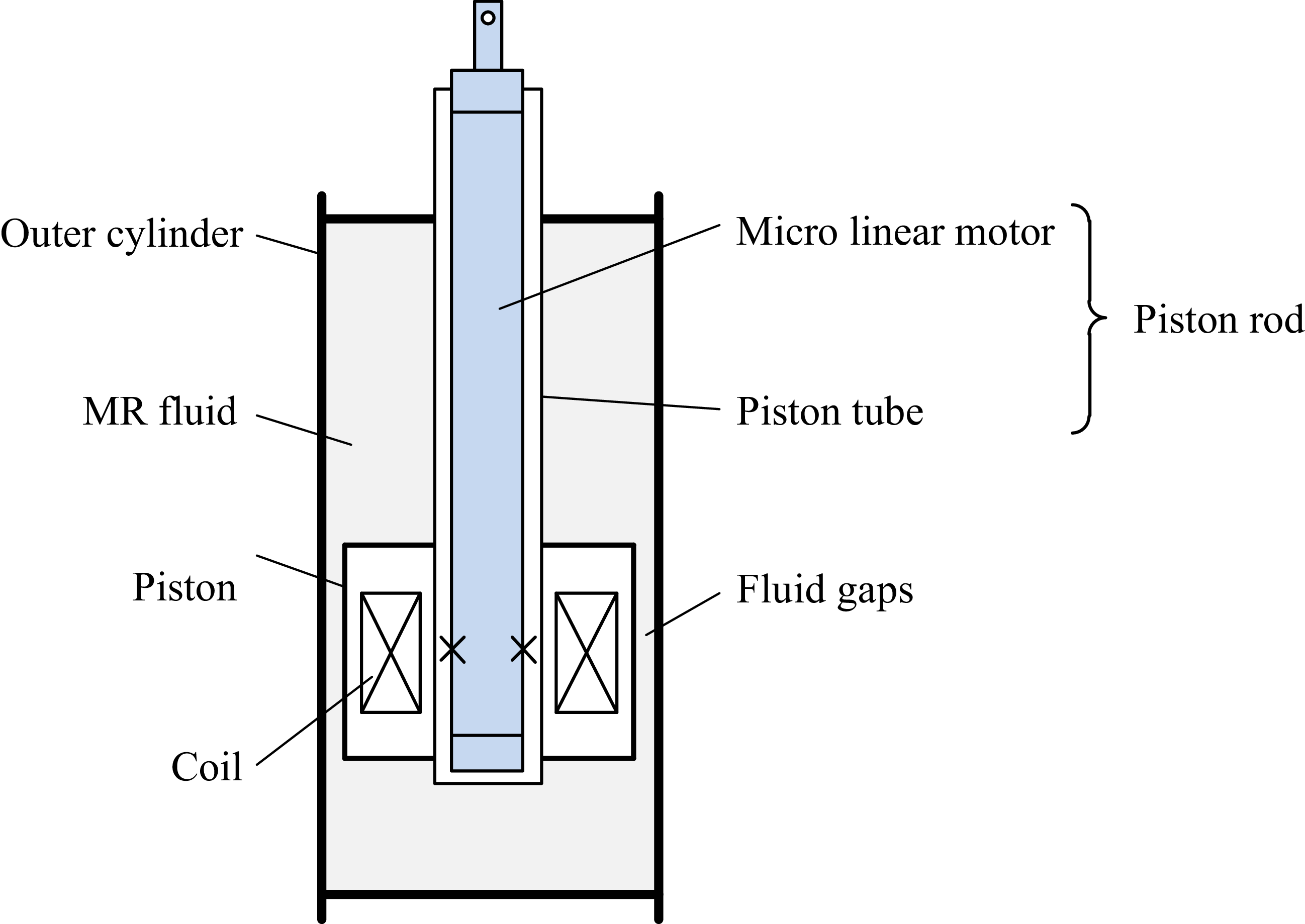
Figure 4 shows the principle of the proposed LMRA, and Figure 5(a) and (b) show its three-dimensional structure and sectional view, respectively. The LMRA consists of an MR damper and a micro linear motor. The MR damper is a double-rod damper, and the micro linear motor is integrated into the piston rod of the damper to form an integrated design.
Principle of the LMRA.

LMRA: (a) the three-dimensional structure and (b) the three-dimensional sectional view.

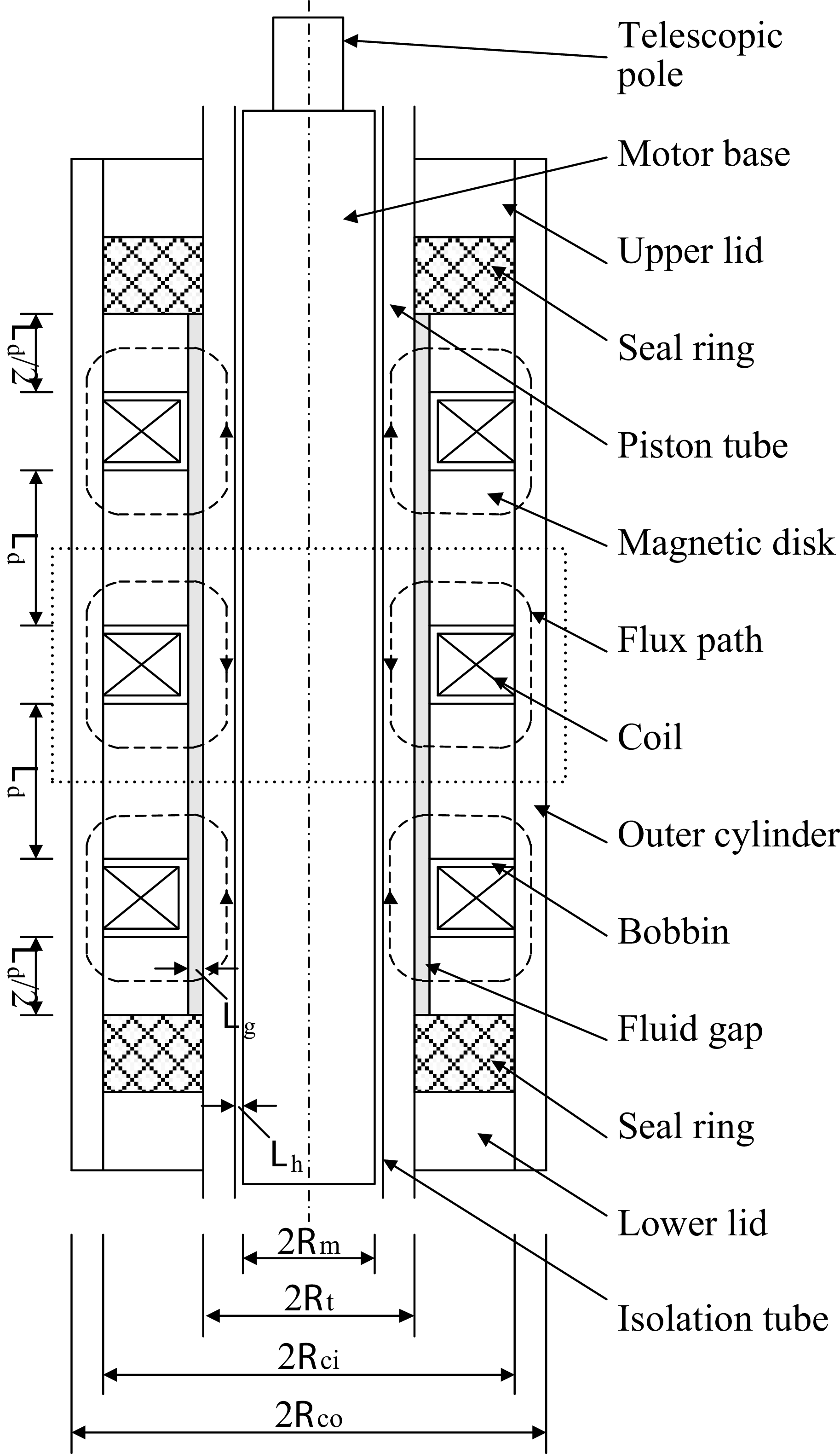
Figure 6 shows the structural schematic of the LMRA. The MR damper mainly consists of a piston tube, an inner cylinder, and an outer cylinder. The inner cylinder includes an upper lid, a lower lid, four magnetic disks, two sealing rings, and three bobbins with wound coils and is firmly fixed inside the outer cylinder. The MR damper used in this study operates in shear mode. MRF fills the fluid gap between the inner cylinder and the piston tube and generates yield shear stress under the excitation current, thereby producing controllable damping force during relative motion. Therefore, the damping force is mainly determined by the excitation current and the relative velocity. The micro linear motor consists of a telescopic pole and a motor base. A lead screw-nut mechanism is adopted inside the motor: the DC motor drives the nut to rotate, thereby driving the telescopic pole to extend and retract. The motor is packaged inside the piston tube and, together with the piston tube, forms the piston rod. The LMRA adopts a three-stage series structure, and the primary structure is indicated by the dashed box in Figure 6. The piston tube, magnetic disks, and outer cylinder are made of 20# steel for high permeability, and the bobbins with wound coils are made of 304 steel for low permeability. Therefore, when the coils are energized, a closed magnetic circuit is formed, and the magnetic flux passes successively through the piston tube, the fluid gap, the magnetic disks, and the outer cylinder. To avoid interference of the damper magnetic field with the micro linear motor, a brass isolation tube is arranged between the motor and the piston tube. It should be noted that this structural principle is also applicable to general linear MR dampers.
Structural schematic diagram of the LMRA.

Figure 6. Long description
A structural schematic diagram of the LMRA. The diagram shows a vertical cross-section of the device with various labeled components. At the top, there is a telescopic pole connected to a motor base. Below the motor base is an upper lid, followed by a seal ring and a piston tube. Inside the piston tube, there is a magnetic disk, a flux path, and a coil. Surrounding these components is an outer cylinder, and a bobbin is situated within the coil. A fluid gap is present below the coil, with another seal ring and a lower lid at the bottom. An isolation tube is shown at the base, with various dimensions and radii labeled around the structure.
SCMRPK in semi-active mode: (a) the motion of the entire four-bar prosthesis and (b) the motion of LMRA.

SCMRPK in active mode: (a) the motion of the entire four-bar prosthesis and (b) the motion of LMRA.

Figure 8. Long description
Panel A: A sequence of diagrams showing the motion of a four-bar prosthesis. The prosthesis is depicted in different positions, with black dots marking key joints and red lines indicating the links. A person is shown using the prosthesis, with close-up views highlighting the movement of the LMRA component. Panel B: Close-up views of the LMRA component during different stages of motion. The component is shown in various positions, with arrows indicating the direction of movement.
Figures 7 and 8 show the working principles of the SCMRPK in the semi-active mode and the active mode, respectively. Figures 7(a) and 8(a) show the overall motion states of the four-bar prosthetic knee joint in the two modes, respectively. In the semi-active mode, the DC motor is powered off, and the screw-nut mechanism is in a self-locking state so that no relative motion occurs between the telescopic pole and the motor base. At this time, the piston rod moves within the inner cylinder, and its relative displacement is regulated by the damping force. As shown in Figure 7(b), the white double-headed arrow indicates the relative displacement between the piston tube and the inner cylinder. By changing the coil current, the damping force of the MR damper can be adjusted, thereby controlling the motion of the four-bar linkage and driving the prosthetic knee joint to the desired angle. In the active mode, a locking current is applied to the coils, and the damper outputs a large damping force so that no relative motion occurs between the piston tube and the inner cylinder. At this time, the DC motor drives the screw-nut mechanism to move the telescopic pole. As shown in Figure 8(b), the white double-headed arrow indicates the relative displacement between the tip of the telescopic pole and the motor base. The motion of the telescopic pole drives the four-bar linkage, thereby moving the prosthetic knee joint to the desired angle.
3. Design of the LMRA magnetic circuit
Since the LMRA consists of three identical primary structures, the dimensional design only needs to be carried out for a single structure. To ensure that the directions of the excitation magnetic fields are consistent in all structures, the winding directions of the coils in adjacent structures are opposite. In this section, a practical dimensional design method is adopted to determine the structural parameters of the MR damper. As shown in Figure 9, the primary structure of the LMRA is divided into six regions: region I is the piston tube, region II is the magnetic disk, region III is the outer cylinder, region IV is the MRF, region V is the micro linear motor, and region VI is the excitation coil;
 $\varPhi_{1}$
,
 $\varPhi_{2}$
,
 $\varPhi_{3}$
, and
 $\varPhi_{4}$
represent the magnetic fluxes in regions I to IV, respectively. It should be noted that the micro linear motor is separated from the magnetic circuit design region by an isolation tube.
Primary structure of the MR damper: (a) overall figure. (b) local figure.

The aim of the dimensional design is to maximize the damping force of the MR damper. To achieve this goal, the main working regions in the magnetic circuit of the primary structure should approach magnetic saturation as simultaneously as possible, while the coil turns are properly matched.
The magnetic circuit of the primary structure is shown by the red dashed line in Figure 9, passing through region I, region IV, region II, region III, region II, region IV, and finally returning to region I. The series magnetic flux
 $\varPhi$
is equal everywhere, which is given by
 \begin{equation} \varPhi _{1}=\varPhi _{2}=\varPhi _{3}=\varPhi _{4} \end{equation}
As shown in Figure 9, the cross-sectional areas of regions I, II, III, and IV in the magnetic circuit vary along the magnetic path. To allow the main working regions in the magnetic circuit to approach magnetic saturation as simultaneously as possible, the minimum cross-sectional area of each of the four regions is designated as the effective cross-sectional area for that region. According to the law of magnetic flux conservation, the magnetic flux of the circuit is given as follows:
 \begin{equation} \varPhi =B_{i}S_{i} \end{equation}
where B i denotes the magnetic flux density in region i, and S i denotes the corresponding effective cross-sectional area.
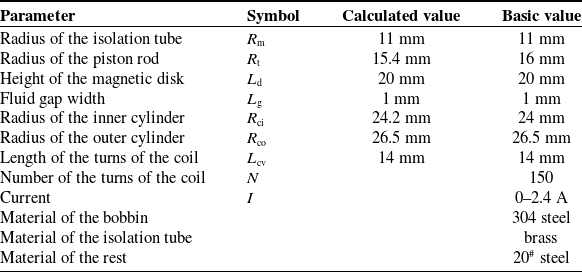
In the magnetic circuit shown in Figure 9, regions I, II, and III are made of 20# steel, while region IV is filled with MRF. The saturation magnetic flux density of 20# steel is denoted by B M (about 1.6 T), whereas the magnetic flux density corresponding to the saturated yield stress of the MRF is denoted by B F (about 0.6 T). To allow the main working regions with different materials to approach magnetic saturation as simultaneously as possible, the effective cross-sectional areas of these regions should be properly allocated. Since the magnetic circuit passes through the MRF and then the 20# steel, and the adjacent regions have similar cross-sectional areas, the MRF region reaches saturation more easily, thereby limiting the further increase in magnetic flux density in the adjacent 20# steel regions. Therefore, the area S 4 of the MRF region should be determined first, followed by the areas S 1 and S 3 of the 20# steel regions that can reach saturation, and finally S 2. The effective cross-sectional areas of all regions are used to determine the calculated dimensional parameters of the primary structure of the LMRA, while the actual dimensions are determined according to manufacturing and assembly requirements. The structural parameters and material properties of the LMRA are listed in Table II.
Dimensional parameters and material properties of the primary structure of the MR damper.

Table II. Long description
A table with 10 rows and 4 columns detailing the dimensional parameters and material properties of a magnetic circuit structure. The columns are labeled Parameter, Symbol, Calculated value, and Basic value. The table lists the radius of the isolation tube, radius of the piston rod, height of the magnetic disk, fluid gap width, radius of the inner cylinder, radius of the outer cylinder, length of the turns of the coil, number of the turns of the coil, current, material of the bobbin, material of the isolation tube, and material of the rest. Each row provides specific values for these parameters.
According to Table II, the maximum magnetic flux in each region can be calculated using Eq. (2) as follows:
 \begin{align} \varPhi _{1\mathrm{s}}&=B_{\mathrm{M}}S_{1}=B_{\mathrm{M}}\times \pi \left[{R}_{\mathrm{t}}^{2}-{R}_{\mathrm{m}}^{2}\right]=678.24 \\[-10pt] \nonumber \end{align}
 \begin{align} \varPhi _{2\mathrm{s}}&=B_{\mathrm{F}}S_{2}=B_{\mathrm{F}}\times \pi \left(R_{\mathrm{t}}+h\right)L_{\mathrm{d}}=640.56 \\[-10pt] \nonumber \end{align}
 \begin{align} \varPhi _{3\mathrm{s}}&=B_{\mathrm{M}}S_{3}=B_{\mathrm{M}}\times \pi \left[{R}_{\mathrm{co}}^{2}-{R}_{\mathrm{ci}}^{2}\right]=634.28 \\[-10pt] \nonumber \end{align}
 \begin{align} \varPhi _{4\mathrm{s}}&=B_{\mathrm{F}}S_{4}=B_{\mathrm{F}}\times \pi R_{\mathrm{t}}L_{\mathrm{d}}=602.88 \\[15pt] \nonumber \end{align}
where
 $\varPhi_{1s}$
,
 $\varPhi_{2s}$
,
 $\varPhi_{3s}$
, and
 $\varPhi_{4s}$
represent the maximum magnetic flux in regions I, II, III, and IV, respectively. Once the magnetic flux in a region reaches its maximum value, it no longer increases. Based on the above calculation results, when region IV, which has the smallest maximum magnetic flux, reaches magnetic saturation, regions I and III also approach saturation almost simultaneously.
After the magnetic flux distribution in the magnetic circuit has been determined, the number of turns of the coil can be obtained according to Kirchhoff’s law for magnetic circuits:
 \begin{equation} NI=\varPhi \sum R \end{equation}
where n is the number of turns of the excitation coil, I is the excitation current on the coil, and ∑ R is the total reluctance of the magnetic circuit. According to Eq. (7), the number of turns n of the coil is approximately 150. The LMRA prototype is shown in Figure 10, and the SCMRPK prototype developed on this basis is shown in Figure 11.
Photographs of the LMRA prototype: (a) components and (b) assembled actuator.

Photograph of the SCMRPK prototype.

4. Simulation and experiment of the LMRA in semi-active mode
According to the Bingham model [Reference Spencer, Dyke, Sain and Carlson43], the damping force (F d) of the MR damper can be represented as
 \begin{equation} F_{\mathrm{d}}={F}_{\mathrm{s}}^{{\unicode[Arial]{x03B7}} }+{F}_{\mathrm{s}}^{{\unicode[Arial]{x03C4}} }\mathrm{sgn}\left({\unicode[Arial]{x0394}} {\, \dot{\kern-1pt d}}\right)=\frac{3\eta {\unicode[Arial]{x0394}} {\, \dot{\kern-1pt d}}L_{\mathrm{d}}w}{L_{\mathrm{g}}}+3\tau _{\mathrm{y}}\left(B\right)L_{\mathrm{d}}w\mathrm{sgn}\left({\unicode[Arial]{x0394}} {\, \dot{\kern-1pt d}}\right) \end{equation}
where F
s
η is the initial viscosity of the MRF, F
s
τ is the yield stress controlled by the external magnetic field intensity, η is the post-yield viscosity of the MRF,
 ${\unicode[Arial]{x0394}} {\, \dot{\kern-1pt d}}$
is the relative velocity between the piston tube and the inner cylinder, w (=2π(R
t+L
g/2)) is the expanded length of the fluid gap, τ
y(B) is the field-dependent yield stress, B is the magnetic flux density of the external magnetic field in the fluid gap, and sgn(.) is the signum function.
The magnetic flux density of each sampling point under different currents.

Table III. Long description
A table comparing the magnetic flux density at three sampling points (A, B, C) under different currents (0.4 A, 0.8 A, 1.2 A, 1.6 A, 2.0 A, 2.4 A). The table has 3 rows and 7 columns. Column headers are: Point, 0.4 A, 0.8 A, 1.2 A, 1.6 A, 2.0 A, 2.4 A. Row labels are: A, B, C. Row A: Point A, 0.37133 T, 0.69420 T, 0.98897 T, 1.24933 T, 1.43514 T, 1.57529 T. Row B: Point B, 0.37725 T, 0.70552 T, 1.00564 T, 1.27304 T, 1.47004 T, 1.62692 T. Row C: Point C, 0.14022 T, 0.26135 T, 0.37160 T, 0.46957 T, 0.54199 T, 0.59952 T.
Yield stress (
 $\tau_{y}$
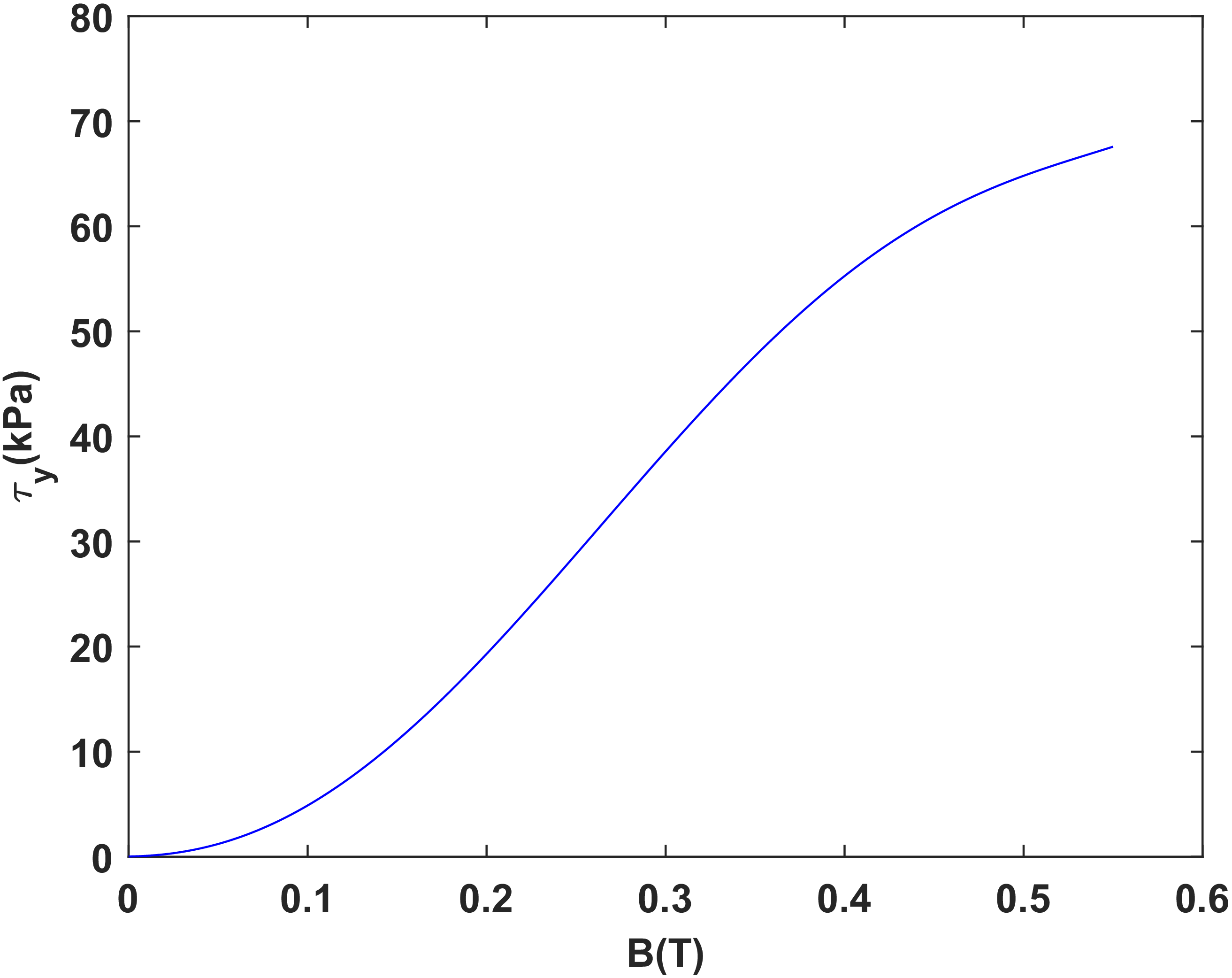
) as a function of magnetic flux density (B) of the MRJ-01.

According to Figure 12, the relationship between the yield stress τ y(B) of the MRF (type:MRJ-01) and the magnetic flux density B can be expressed as follows
 \begin{equation} \tau _{\mathrm{y}}\left(B\right)=a_{\mathrm{y}5}B^{5}+a_{\mathrm{y}4}B^{4}+a_{\mathrm{y}3}B^{3}+a_{\mathrm{y}2}B^{2}+a_{\mathrm{y}1}B+a_{\mathrm{y}0} \end{equation}
where a y5 = 4.583 × 10³ kPa/T5, a y4 = −5.700 × 10³ kPa/T4, a y3 = 1.486 × 10³ kPa/T3, a y2 = 3.630 × 10² kPa/T2, a y1 = 2.628 kPa/T, and a y0 = 2.100 × 10⁻² kPa.
Figure 13 shows the magnetic flux density distribution in the fluid gap (region IV) under the maximum current excitation of 2.4 A. Sampling points A, B, and C are located at the middle positions of regions I, III, and IV, respectively, and are used to represent the magnetic flux densities in these regions. The magnetic flux densities at the sampling points under different current excitations are listed in Table III. The results show that the magnetic flux density in each region gradually increases with current and approaches saturation at 2.4 A.
The contour of magnetic flux density (values in T) under a 2.4 A current excitation.

Calculated damping forces of the integrated MR damper under a 0.5 Hz sinusoidal displacement excitation with an amplitude of 10 mm: (a) the force versus velocity and (b) the force versus displacement.

According to Figure 13 and Table III, the relationship between the magnetic flux density in the fluid gap and the excitation current can be expressed as follows:
 \begin{equation} B=f(I)=b_{2}I^{2}+b_{1}I+b_{0} \end{equation}
where b 2 = −5.794 × 10⁻², b 1 = 0.3716, b 0 = −3.695 × 10⁻³.
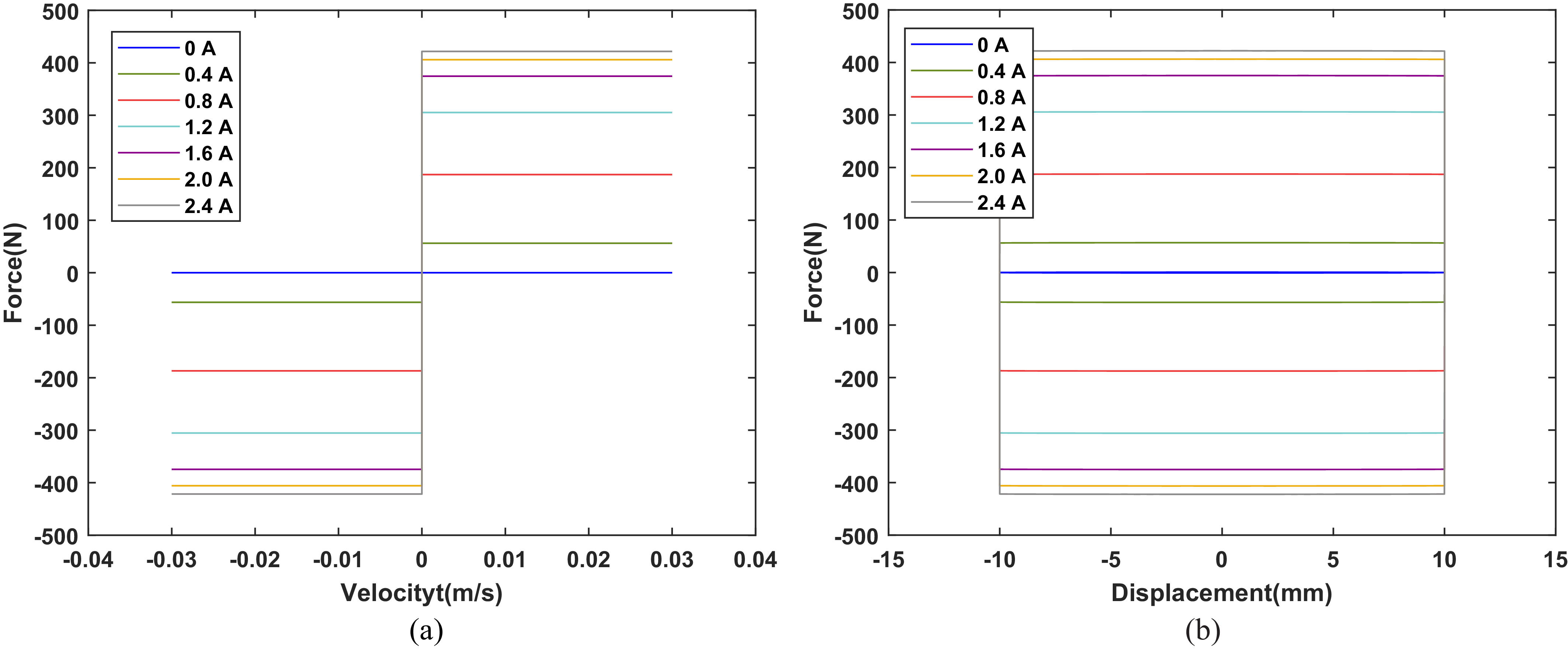
According to Eq. (8)–(10), adjusting the current in the excitation coil changes the magnetic flux density in the fluid gap and thereby produces a controllable damping force in the MR damper. In the semi-active mode, the LMRA can be regarded as an MR damper. The damping-force characteristics of the MR damper under different excitation conditions can therefore be calculated from Eq. (8)–(10). Figure 14 shows the calculated results under a 0.5 Hz sinusoidal displacement excitation with an amplitude of 10 mm. The calculated results show that the damping force reaches about 421 n at 2.4 A. To obtain damping-force data closer to the actual values, the MR damper was tested using a shock testing machine (LFV-50.HH, Walter+Bai AG), and the experimental setup is shown in Figure 15. Figure 16 shows the measured results under the same excitation conditions. The measured damping force reaches about 367 n at 2.4 A. The measured results are slightly lower than the calculated results, mainly because the MRF cannot completely fill the cavity and perfect sealing is difficult to achieve in the experiment. Therefore, some deviation exists between the experimental and simulation results. These results demonstrate that the dimensional design method adopted for the LMRA is effective.
Experimental setup for the semi-active mode experiment of LMRA.

Measured damping forces of the integrated MR damper under a 0.5 Hz sinusoidal displacement excitation with an amplitude of 10 mm: (a) the force versus velocity and (b) the force versus displacement.

Figure 16. Long description
Two line graphs depict the measured damping forces of an integrated MR damper under a 0.5 Hz sinusoidal displacement excitation with an amplitude of 10 mm. Panel A: The line graph shows the relationship between force (in Newtons) and velocity (in meters per second). The x-axis ranges from -0.04 to 0.04 m/s, and the y-axis ranges from -400 to 400 N. Multiple lines represent different current values (0 A, 0.4 A, 0.8 A, 1.2 A, 1.6 A, 2.0 A, and 2.4 A), showing how the force changes with velocity for each current. Panel B: The line graph shows the relationship between force (in Newtons) and displacement (in millimeters). The x-axis ranges from -15 to 15 mm, and the y-axis ranges from -400 to 400 N. Similar to Panel A, multiple lines represent different current values, illustrating how the force changes with displacement for each current.
To suppress the influence of the damper magnetic field on the micro linear motor, a 1 mm thick brass isolation tube was arranged between the motor and the piston tube. As shown in Figures 17 and 18, comparative simulations were carried out for the two structures with and without the isolation tube under the 2.0 A condition. The simulation results show that, without the isolation tube, part of the magnetic flux lines enters the motor region and may affect its normal operation. After the isolation tube is introduced, the magnetic flux lines are effectively confined within the designed magnetic circuit, and the magnetic flux density in the motor region is significantly reduced. This indicates that the isolation tube can effectively isolate magnetic field interference and satisfies the structural design requirements.
Finite element method analysis of the LMRA without isolation tube: (a) Contour of magnetic flux density (values in T) and (b) Magnetic flux distribution.

Finite element method analysis of the LMRA with isolation tube: (a) Contour of magnetic flux density (values in T) and (b) Magnetic flux distribution.

Figure 18. Long description
Panel A: A heat map showing the contour of magnetic flux density. The x and y axes are not labeled. The color scale ranges from 0.276E-17 to 1.51353, with blue indicating lower values and red indicating higher values. The map shows a central region with higher magnetic flux density surrounded by areas of lower density. Specific values are labeled at various points within the map. Panel B: A contour plot showing the magnetic flux distribution. The x and y axes are not labeled. The plot features concentric lines indicating different levels of magnetic flux. The lines are closer together in the center, indicating higher flux density, and spread out towards the edges, indicating lower flux density.
5. Kinematic and dynamic modeling of the SCMRPK
As shown in Figure 19, the SCMRPK-based lower limb prosthesis consists of the SCMRPK prototype, a prosthetic shank, and a prosthetic foot. The thigh synchronization mechanism (TSM) is affixed to the test subject’s thigh and moves synchronously with it through restraint. The prosthesis is installed at the knee joint of the subject using a specially designed connector located at the lower end of the TSM.
The photograph of the SCMRPK-based lower limb prosthesis.

The normal gait cycle consists of the stance and swing phases. Since prosthetic knee joints based on four-bar linkage mechanisms can achieve stability in the stance phase through self-regulation [Reference Grimes, Flowers and Donath44, Reference Grimes45], this paper focuses on the kinematic characteristics of the SCMRPK in the swing phase.
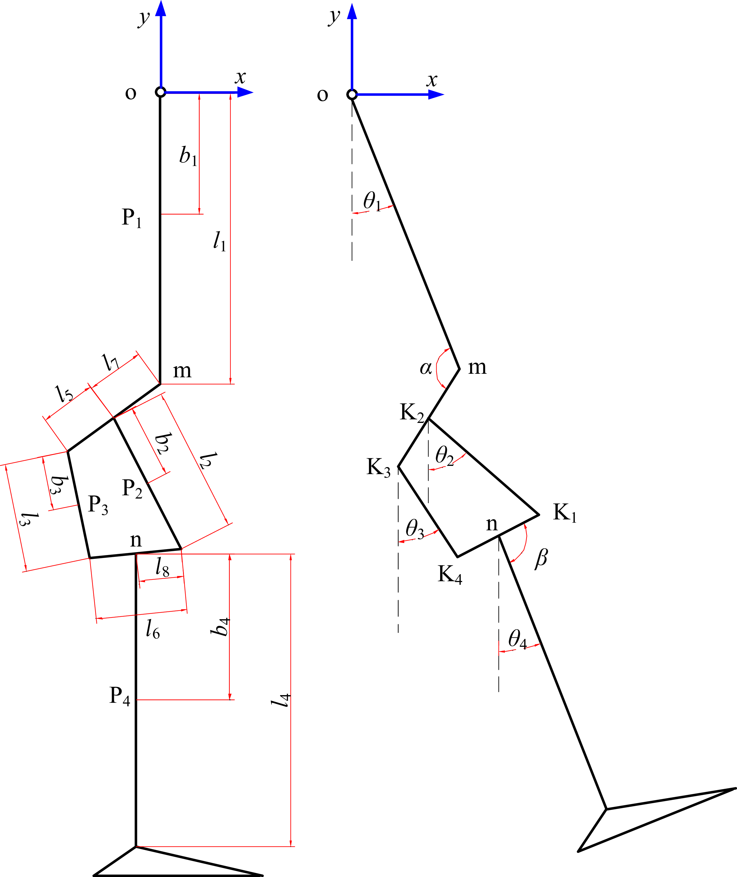
As shown in Figure 20, the point o represents the hip joint; the point K j represents the jth (j = 1,…,4) axis of the four-bar linkage; the point n represents the intersection point of the fourth and sixth link rods; the second, third, fifth, and sixth link rods represent the front, back, upper, and lower link rods, respectively; the first link rod represents the thigh; the fourth link rod represents the shank; the point P i represents the center of mass of the ith (i = 1,…,4) link rod.
Equivalent diagram of the lower limb prosthesis.

Figure 20. Long description
Panel A: A schematic diagram of a lower limb prosthesis with labeled components. The diagram includes a vertical structure with segments labeled P1, P2, P3, and P4, connected by joints labeled m and n. The lengths of these segments are denoted as l1, l2, l3, l4, l5, l6, l7, and l8. The distances from the origin to the segments are labeled as b1 and b4. Panel B: A mechanical representation of the lower limb prosthesis with angles θ1, θ2, θ3, θ4, and β marked at various joints. The segments are labeled as K1, K2, K3, and K4, with lengths denoted as l1, l2, l3, and l4. The angles and lengths illustrate the mechanical movement and structure of the prosthesis.
According to Lagrange’s second kinetic equation, the governing equation of the lower limb prosthesis in the swing phase is given by
 \begin{equation} \begin{cases} L=\sum\limits_{i=1}^{4}\left(E_{i}-V_{i}\right)=\sum\limits_{i=1}^{4}\left[\dfrac{1}{2}m_{i}\left({\dot{x}}_{i}^{2}+{\dot{y}}_{i}^{2}\right)+\dfrac{1}{2}J_{i}{\dot{\theta }}_{i}^{2}-m_{i}gy_{i}\right]\\[10pt] \left[\begin{array}{cccc} 1 &\quad -1 & \quad -1 &\quad 0\\[3pt] 0 &\quad 1 &\quad 0 &\quad -1\\[3pt] 0 &\quad 0 &\quad 1 &\quad -1\\[3pt] 0 &\quad 0 &\quad 0 &\quad 1 \end{array}\right]\left[\begin{array}{l} T_{1}\\[3pt] T_{2}\\[3pt] T_{3}\\[3pt] T_{4} \end{array}\right]=\left[\begin{array}{l} \dfrac{d}{dt}\left(\dfrac{\partial L}{\partial \dot{\theta }_{1}}\right)-\dfrac{\partial L}{\partial \dot{\theta }_{1}}\\[10pt] \dfrac{d}{dt}\left(\dfrac{\partial L}{\partial \dot{\theta }_{2}}\right)-\dfrac{\partial L}{\partial \dot{\theta }_{2}}\\[10pt] \dfrac{d}{dt}\left(\dfrac{\partial L}{\partial \dot{\theta }_{3}}\right)-\dfrac{\partial L}{\partial \dot{\theta }_{3}}\\[10pt] \dfrac{d}{dt}\left(\dfrac{\partial L}{\partial \dot{\theta }_{4}}\right)-\dfrac{\partial L}{\partial \dot{\theta }_{4}} \end{array}\right] \\[55pt] =\left[\begin{array}{llll} M_{11} &\quad M_{12} &\quad M_{13} &\quad M_{14}\\[3pt] M_{21} &\quad M_{22} &\quad M_{23} &\quad M_{24}\\[3pt] M_{31} &\quad M_{32} &\quad M_{33} &\quad M_{34}\\[3pt] M_{41} &\quad M_{42} &\quad M_{43} &\quad M_{44} \end{array}\right]\left[\begin{array}{l} \ddot{\theta }_{1}\\[3pt] \ddot{\theta }_{2}\\[3pt] \ddot{\theta }_{3}\\[3pt] \ddot{\theta }_{4} \end{array}\right]+\left[\begin{array}{l} C_{1}\\[3pt] C_{2}\\[3pt] C_{3}\\[3pt] C_{4} \end{array}\right]+\left[\begin{array}{l} G_{1}\\[3pt] G_{2}\\[3pt] G_{3}\\[3pt] G_{4} \end{array}\right] \end{cases} \end{equation}
where L is the Lagrange function of the multi-rigid-body system; E
i
is the kinetic energy of the ith link rod;
 ${V_{\!i}}$
is the potential energy of the ith link rod; θ
i
is the relative angle between the ith link rod and the vertical direction; x
i
is the horizontal coordinate of the point P
i;
y
i
is the vertical coordinate of the point P
i
; m
i
is the mass of the ith link rod; J
i
is the moment of inertia of the ith link rod; T
i
is the generalized torque corresponding to θ
i
; M
ij
is a component of the inertia matrix; C
i
is a component of the centripetal and Coriolis torque matrix; and G
i is a component of the gravitational torque and hip acceleration matrix.
Considering that the four-bar linkage is a closed-loop structure, the constraint equation about Eq. (11) is given by
 \begin{align} \begin{cases} l_{5}\cos \left(\dfrac{\pi }{2}+\alpha +\theta _{1}\right)+l_{2}\cos \left(\dfrac{\pi }{2}+\theta _{2}\right)=l_{3}\cos \left(\dfrac{\pi }{2}+\theta _{3}\right)+l_{6}\cos \left(\dfrac{\pi }{2}+\beta +\theta _{4}\right)\\[8pt] l_{5}\sin \left(\dfrac{\pi }{2}+\alpha +\theta _{1}\right)+l_{2}\sin \left(\dfrac{\pi }{2}+\theta _{2}\right)=l_{3}\sin \left(\dfrac{\pi }{2}+\theta _{3}\right)+l_{6}\sin \left(\dfrac{\pi }{2}+\beta +\theta _{4}\right) \end{cases} \end{align}
where l
i
is the length of the ith (i = 1,…,8) link rod;
 $\alpha$
is the angle between the first link rod and the seventh link rod; and
 $\beta$
is the angle between the fourth link rod and the sixth link rod.
According to Eq. (11), when T 3 = 0 and T 4 = 0, the torque (T 2) around the axis K 2 is given by
 \begin{equation} T_{2}=\frac{d}{dt}\left(\frac{\partial L}{\partial \dot{\theta }_{2}}\right)-\frac{\partial L}{\partial \dot{\theta }_{2}}=M_{21}\ddot{\theta }_{1}+M_{22}\ddot{\theta }_{2}+M_{23}\ddot{\theta }_{3}+M_{24}\ddot{\theta }_{4}+C_{2}+G_{2} \end{equation}
where M 21, M 22, M 23, M 24, C 2, G 2, and J 2 are governed by
 \begin{align*} \begin{array}{c} M_{21}=m_{2}l_{7}b_{2}\sin \alpha \sin \left(\theta _{1}-\theta _{2}\right)-m_{2}b_{2}\left(l_{7}\cos \alpha -l_{1}\right)\cos \left(\theta _{1}-\theta _{2}\right)\\[5pt]\quad \quad \ \ +m_{4}l_{2}l_{7}\sin \alpha \sin \left(\theta _{1}-\theta _{2}\right)-m_{4}l_{2}\left(l_{7}\cos \alpha -l_{1}\right)\cos \left(\theta _{1}-\theta _{2}\right) \end{array} \\[-28pt] \end{align*}
 \begin{align*} M_{22}=J_{2}+m_{2}{b}_{2}^{2}+m_{4}{l}_{2}^{2} \end{align*}
 \begin{align*} M_{23}=0 \\[-25pt] \end{align*}
 \begin{align*} M_{24}=m{4}^{}{l}{_{2}^{}}b_{4}\cos \left(\theta _{4}-\theta _{2}\right)-m_{4}l_{2}l_{8}\cos \left(\theta _{4}-\theta _{2}+\beta \right) \\[-25pt] \end{align*}
 \begin{align*} \begin{array}{c} C_{2} =\left[\begin{array}{l} m_{2}l_{7}b_{2}\sin \alpha \cos \left(\theta _{1}-\theta _{2}\right)+m_{2}b_{2}\left(l_{7}\cos \alpha -l_{1}\right)\sin \left(\theta _{1}-\theta _{2}\right)\\[3pt] +m_{4}l_{2}l_{7}\sin \alpha \cos \left(\theta _{1}-\theta _{2}\right)+m_{4}l_{2}\left(l_{7}\cos \alpha -l_{1}\right)\sin \left(\theta _{1}-\theta _{2}\right) \end{array}\right]{\dot{\theta }}_{1}^{2}\\[10pt] +\left[m_{4}l_{2}l_{8}\sin \left(\theta _{4}-\theta _{2}+\beta \right)-m_{4}l_{2}b_{4}\sin \left(\theta _{4}-\theta _{2}\right)\right]{\dot{\theta }}_{4}^{2} \qquad \quad \quad \quad \end{array} \\[-25pt] \end{align*}
 \begin{align*} G_{2}=\left(m_{2}b_{2}\cos \theta _{2}+m_{4}l_{2}\cos \theta _{2}\right)\ddot{x}_{\mathrm{o}}+\left(m_{2}b_{2}\sin \theta _{2}+m_{4}l_{2}\sin \theta _{2}\right)\ddot{y}_{\mathrm{o}}+m_{2}gb_{2}\sin \theta _{2}+m_{4}gl_{2}\sin \theta _{2} \\[-25pt] \end{align*}
 \begin{align*} J_{2}=m_{2}{b}_{2}^{2}/12 \\[-10pt]\end{align*}
where (x o, y o) is the coordinate of the point o; g (g = 9.8) is the gravity; b 1 is the distance from the point o to the point P 1; b 2 is the distance from the point K 2 to the point P 2; b 3 is the distance from the point K 3 to the point P 3; and b 4 is the distance from the point n to the point P 4.
As shown in Figure 2(b), the actuating mechanism of the SCMRPK is the LMRA, which generates the torque (T 2) around the axis K 2. The damping force of the MR damper (F damper) is determined by the relative velocity between the piston rod and the inner cylinder and the current in the coils. The relative velocity between the piston rod and the inner cylinder, as well as the coil current, is independent of θ 1.
Equivalent diagram of the SCMRPK when θ 1 is equal to 0.

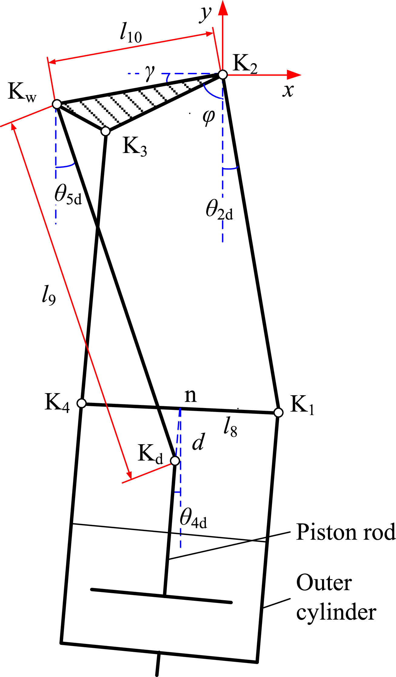
Figure 21 shows the equivalent diagram of the SCMRPK when θ 1 is equal to 0. K d and K w denote the hinge points between the piston rod and the swing link and between the thigh connector and the swing link, respectively. The ninth link rod represents the swing link rod, and the triangle K w K 2 K 3 represents the thigh connector. According to the virtual work principle, the relationship between the torque (T 2) around the axis K 2 and the F damper in the direction of the piston rod is given by
 \begin{equation} T_{2}\delta \theta _{2\mathrm{d}}=F_{\text{damper}}\delta d \end{equation}
where d is the distance from the point
 $K_{\textrm{d}}$
to the sixth link rod in the direction of the piston rod;
 $\theta_{2{\textrm{d}}}$
is the angle between the second link rod and the vertical direction when
 $\theta_{1}$
is equal to 0;
 $\delta \theta_{2{\textrm{d}}}$
is the virtual displacement of
 $\theta_{2{\textrm{d}}}$
; and δ
d is the virtual displacement of d.
Considering the closed-loop path (K 2 K w K d nK 1 K 2) as shown in Figure 20, the constraint equation about Eq. (14) is given by
 \begin{align} \begin{cases} l_{2}\cos \left(\dfrac{\pi }{2}+\theta _{2\mathrm{d}}\right)+l_{10}\cos \left(\pi +\gamma \right)+d\cos \left(\dfrac{\pi }{2}+\theta _{4\mathrm{d}}\right)=l_{9}\cos \left(\dfrac{\pi }{2}+\theta _{5\mathrm{d}}\right)+l_{8}\cos \left(\dfrac{\pi }{2}+\beta +\theta _{4\mathrm{d}}\right)\\[8pt] l_{2}\sin \left(\dfrac{\pi }{2}+\theta _{2\mathrm{d}}\right)+l_{10}\sin \left(\pi +\gamma \right)+d\sin \left(\dfrac{\pi }{2}+\theta _{4\mathrm{d}}\right)=l_{9}\sin \left(\dfrac{\pi }{2}+\theta _{5\mathrm{d}}\right)+l_{8}\sin \left(\dfrac{\pi }{2}+\beta +\theta _{4\mathrm{d}}\right) \end{cases} \\[-20pt] \nonumber \end{align}
where l i is the length of the ith (i = 9, 10) link rod; γ is the angle between the tenth link rod and the horizontal direction; θ 4d is the angle between the fourth link rod and the vertical direction when θ 1 is equal to 0; and θ 5d is the angle between the ninth link rod and the vertical direction when θ 1 is equal to 0.
According to Figures 20 and 21, the relative angle (θ 4d) between the thigh and the shank, which is the knee angle of the SCMRPK, is
 \begin{equation} \theta _{4d}=\theta _{4}-\theta _{1} \end{equation}
The relative angle (θ 2d) between the second link rod and the vertical direction is
 \begin{equation} \theta _{2\mathrm{d}}=\theta _{2}-\theta _{1} \end{equation}
where
 $\varphi$
is the angle between the fifth link rod and the vertical direction when θ
1 is equal to 0.
According to Eqs. (12) and (15), the relationship between θ 4d and θ 2d is
 \begin{equation} \begin{array}{l} \theta _{4\mathrm{d}} =\arcsin \dfrac{{l_{2}}^{2}+{l_{5}}^{2}+{l_{6}}^{2}-{l_{3}}^{2}+2l_{2}l_{5}\cos \left(\theta _{2\mathrm{d}}-\alpha \right)}{-2l_{6}\sqrt{{l_{2}}^{2}+{l_{5}}^{2}+2l_{2}l_{5}\cos \left(\theta _{2\mathrm{d}}-\alpha \right)}}\\[15pt] \quad \quad +\text{arctg}\dfrac{l_{5}\sin \left(\alpha \right)+l_{2}\sin \left(\theta _{2\mathrm{d}}\right)}{l_{5}\cos \left(\alpha \right)+l_{2}\cos \left(\theta _{2\mathrm{d}}\right)}-\beta +\dfrac{\pi }{2} \end{array} \end{equation}
According to Eq. (15), the displacement (Δd) of K d in the direction of the piston rod is
 \begin{align} \begin{array}{l} {\unicode[Arial]{x0394}} d=l_{8}\cos \beta -l_{2}\cos \left(\theta _{2\mathrm{d}}-\theta _{4\mathrm{d}}\right)-l_{10}\sin \left(\theta _{4\mathrm{d}}-\gamma \right)-d_{0}\\[8pt]\quad \quad \ +\sqrt{\begin{array}{l} {l}_{9}^{2}-{l}_{2}^{2}-{l}_{10}^{2}-{l}_{8}^{2}+2l_{8}l_{10}\sin \left(\beta +\theta _{4\mathrm{d}}-\gamma \right)-2l_{2}l_{10}\sin \left(\theta _{2\mathrm{d}}-\gamma \right)\\[3pt] +2l_{2}l_{8}\cos \left(\beta +\theta _{4\mathrm{d}}-\theta _{2\mathrm{d}}\right)+\left(l_{2}\cos \left(\theta _{2\mathrm{d}}-\theta _{4\mathrm{d}}\right)+l_{10}\sin \left(\theta _{4\mathrm{d}}-\gamma \right)-l_{8}\cos \beta \right)^{2} \end{array}} \end{array} \end{align}
where d 0 is the initial length of the telescopic pole, θ 4d = 0.
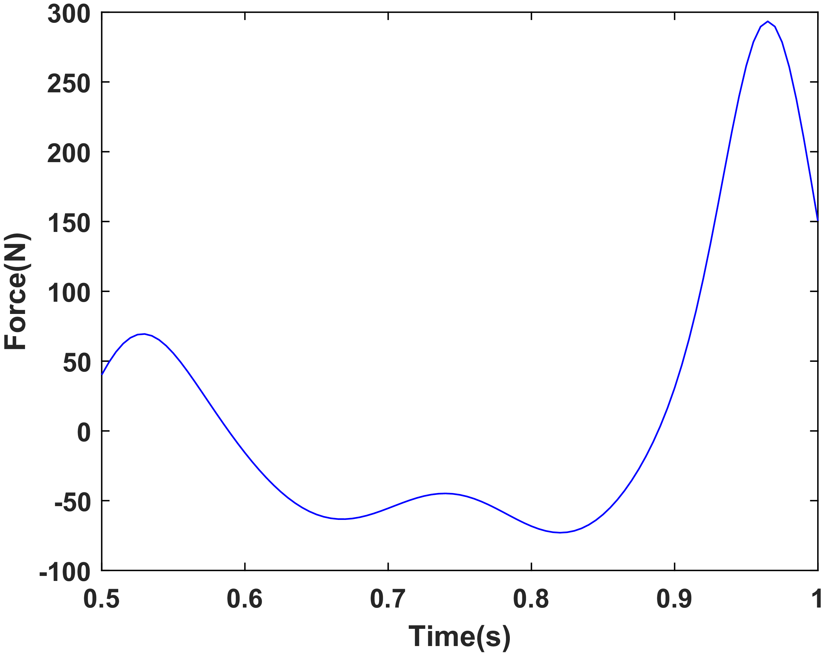
Based on the established dynamic model, Figure 22 shows the time-history curve of the damping force required from the MR damper during the swing phase of the prosthetic knee joint with a gait cycle of 1 s. As shown in Figure 22, the maximum required damping force is 293 N. Therefore, to satisfy the damping requirement under this gait condition, the maximum damping force of the MR damper should exceed 293 N. The experimental results in Section 4 show that the maximum damping force of the MR damper reaches 367 N, which is higher than the design requirement. This indicates that the semi-active mode of the LMRA is feasible.
Time history of the required damping force of the MR damper of the prosthetic knee joint during the swing phase with a gait cycle of 1 s.

6. Control method of the SCMRPK
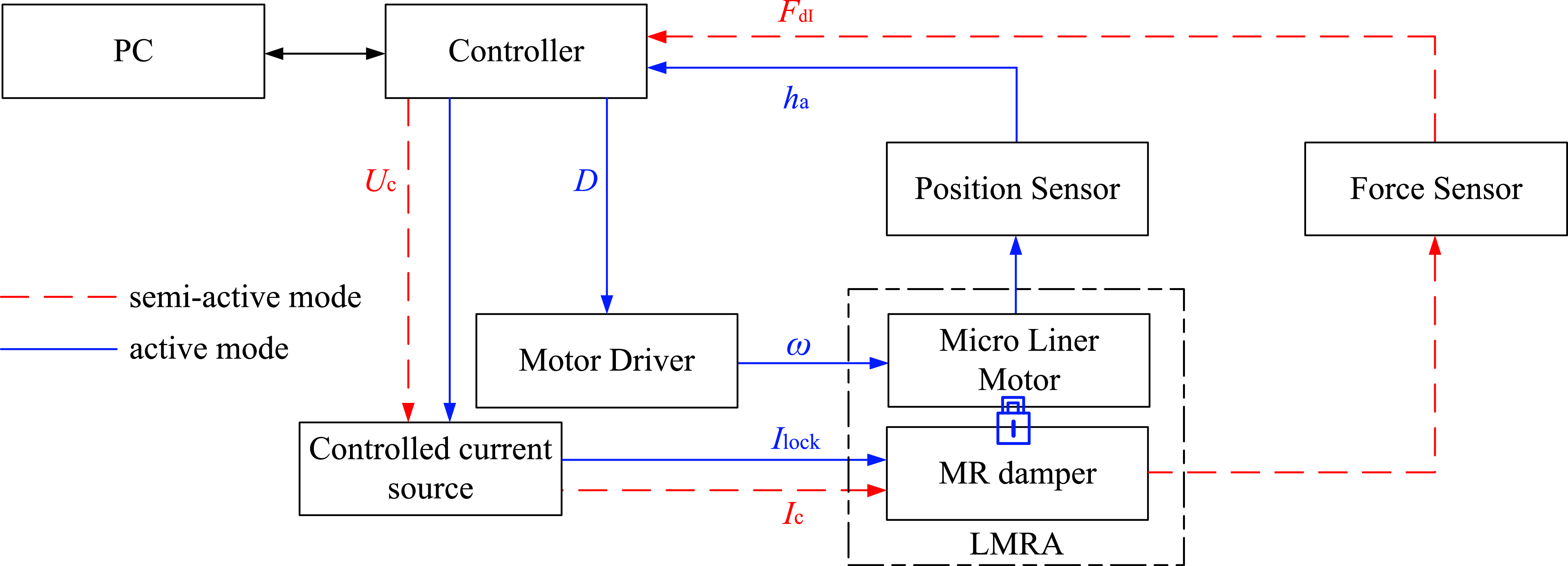
Both the driving and damping regulation of the SCMRPK are realized by the LMRA. The LMRA can output active driving force and controllable damping force, allowing the SCMRPK to operate in both active and semi-active modes. This section introduces the control methods for these two modes, and the block diagram of the control system is shown in Figure 23. The SCMRPK control system mainly consists of a controller, a controlled current source, position sensors, a force sensor, a motor driver, and the LMRA.
Block diagram of the control system for the SCMRPK.

6.1 Semi-active control method
The red dashed loop in Figure 23 represents the semi-active mode control loop. In the semi-active mode, the SCMRPK adopts the computed torque and PD feedback control algorithm to achieve trajectory tracking, which is realized by regulating the damping force of the MR damper to control the prosthetic knee joint angle θ 4d.
According to Eqs. (13), (14), (16), and (18), the controlled damping force (F dC) generated by the MR damper is given by
 \begin{equation} \begin{array}{ll} F_{\mathrm{dC}} & =T_{2\mathrm{C}}\dfrac{\delta \theta _{2\mathrm{d}}}{\delta d}=T_{2\mathrm{C}}\dfrac{\partial \theta _{2\mathrm{d}}}{\partial {\unicode[Arial]{x0394}} d}\\[8pt] & =\left[M_{21}\ddot{\theta }_{1}+M_{22}\left(\ddot{\theta }_{\mathrm{d}2}+K_{\mathrm{D}1}{\, \dot{\kern-1pt e}}_{f}+K_{\mathrm{P}1}e_{f}\right)+M_{23}\ddot{\theta }_{3}+M_{24}\ddot{\theta }_{4}+C_{2}+G_{2}\right]\dfrac{\partial \theta _{2\mathrm{d}}}{\partial {\unicode[Arial]{x0394}} d} \end{array} \end{equation}
where T 2C is the controlled torque around the axis K 2; θ d2, which is calculated using both Eq. (18) and the reference knee angle, is the reference knee angle of θ 2; e f (=θ d2–θ 2) is the tracking error; K P1 is the proportionality factor, and K D1 is the derivative time constant.
Considering that the MR damper can only provide the passive damping force, the MR damper is unable to provide the necessary active force when the F dC is positive during the swing’s flexion phase or negative during the swing’s extension phase. The damping force (F dI) provided by the MR damper can be determined by
 \begin{equation} \begin{array}{l} \begin{array}{ll} if & \dot{\theta }_{2\mathrm{d}}\leq 0 \end{array}\\[5pt] F_{\mathrm{dI}}=\begin{cases} F_{\text{dmax}} & F_{\mathrm{dC}}\lt -F_{\text{dmax}}\\[3pt] F_{\text{dmin}} & F_{\mathrm{dC}}\gt -F_{\text{dmin}}\\[3pt] -F_{\mathrm{dC}} & \textit{otherwise} \end{cases} \\[28pt] \begin{array}{ll} if & \dot{\theta }_{2\mathrm{d}}\gt 0 \end{array}\\[5pt] F_{\mathrm{dI}}=\begin{cases} F_{\text{dmax}} &\ F_{\mathrm{dC}}\gt F_{\text{dmax}}\\[3pt] F_{\text{dmin}} & F_{\mathrm{dC}}\lt F_{\text{dmin}}\\[3pt] F_{\mathrm{dC}} & \textit{otherwise} \end{cases} \end{array} \end{equation}
where F dmax is the maximum damping force generated by the MR damper and F dmin is the damping force generated by the MR damper with the current of 0 A.
According to Eqs. (20) and (21), the required F dI provided by the MR damper can be achieved by adjusting the current in the excitation coil (I c).
To accurately determine the controlled current of the MR damper, its current-driving equation was established based on the experimental data in Section 4, as follows:
 \begin{equation} I_{\mathrm{c}}=c_{3}{F}_{\mathrm{dM}}^{3}+c_{2}{F}_{\mathrm{dM}}^{2}+c_{1}F_{\mathrm{dM}}+c_{0} \end{equation}
where c 3 = 2.246 × 10⁻⁷, c 2 = 1.22 × 10⁻⁵, c 1 = 2.269 × 10⁻², and c 0 = −0.5731; F dM is the measured damping force of the MR damper.
The relationship between the controlled current in the coils (I c) output from the controlled current source and the input control voltage (U c) can be expressed as follows:
 \begin{equation} U_{c}=k_{I}I_{c} \end{equation}
where k I is the proportionality factor of the controlled current source.
According to Eqs. (20), (22), and (23), the F dI of the LMRA can be generated by adjusting the input voltage (U c), thereby controlling the flexion angle (θ 4d) of the prosthetic knee joint.
6.2 Active control method
In the active mode, the prosthetic knee joint is actively driven by controlling the micro linear motor to drive the telescopic pole. The blue loop in Figure 23 represents the active mode control loop. The controller applies a locking current I lock to the coils so that the damper outputs a large damping force and the system can be regarded as approximately rigidly connected. When the load force is smaller than the damping force, the relative displacement between the piston tube and the outer cylinder can be neglected.
For the micro linear motor, PD control is adopted to output the PWM duty cycle (D) so as to regulate the motor speed and thereby control the displacement of the telescopic pole. According to Eqs. (16)–(19), the displacement of the telescopic pole can be converted into the angle θ 2d of the second link relative to the vertical direction, thereby realizing the control of the knee flexion angle θ 4d. The control process can be expressed as follows:
 \begin{align} \begin{cases} e_{\theta }=\theta _{\mathrm{d}2\mathrm{d}}-\theta _{2d}\\[3pt] D=k_{1}e_{\theta }\\[3pt] \omega =K_{\mathrm{D}2}\dot{D}+K_{\mathrm{P}2}D \end{cases} \end{align}
where θ d2d is the reference angle of θ 2d calculated according to Eqs. (17), (18) and the reference angle of the knee joint; e θ (=θ d2d–θ 2d) is the tracking error; k 1 is the proportionality factor between the duty cycle and the tracking error; K P2 is the proportionality factor, and K D2 is the derivative time constant.
According to the above control method, in the semi-active mode, the motor does not operate and the damping force is regulated by the current I c; in the active mode, the motor operates and the damper is controlled by the locking current I lock. Switching between the two modes is realized through motor start-stop control and switching of the control current (I c and I lock).
7. Testing of LMRA in active mode
7.1. Experiment setup
To verify the performance of the LMRA in active mode, the experimental setup shown in Figure 24 was established. The setup mainly consists of the LMRA prototype, a controller (type: NI myRIO-1900, National Instruments), a micro linear motor (type: BTL-20, maximum speed: 20 mm/s, maximum force: 150 N, Changzhou Louie Linear Actuator Company), a motor driver, two position sensors (type: MIRAN KPM18, Shenzhen MIRAN Company), a force sensor (type: DYMH-103, Bengbu Dayang Company), and a signal amplifier (type: DY510-4, Bengbu Dayang Company).
The experimental setup of LMRA in active mode.

Figure 24. Long description
A diagram of an experimental setup for verifying the performance of a linear motor-driven actuator in active mode. The setup includes a linear motor driver connected to a controlled current source, which is linked to an NI myrio-1900 device. This device is connected to a computer through a signal amplifier. The linear motor driver is connected to an LMRA prototype. The LMRA prototype is connected to a force sensor and two position sensors. The force sensor is connected to a spring. The position sensors are labeled as Position Sensor 1 and Position Sensor 2. The LMRA prototype is mounted on a metal base.
As shown in Figure 24, the LMRA prototype and the two position sensors are fixed to the experimental platform. The force sensor is mounted between the motor’s telescopic pole and the spring to measure the output force of the LMRA, while the spring is used to simulate the load.
The sensing end of position sensor 1 is fixed to the force sensor and is used to measure the position of the motor’s telescopic pole, whereas the sensing end of position sensor 2 is fixed to the piston rod and is used to measure the displacement of the outer cylinder of the damper relative to the micro linear motor. The controller regulates the controlled current source to supply the locking current I lock to the coil. The sensor signals are amplified by the signal amplifier before being sent to the controller. Based on these signals, the controller outputs control signals to the motor driver, thereby controlling the motion of the motor telescopic pole.
7.2. Experiment results and analysis
As long as the damping force generated by the locking current exceeds the load force, the corresponding current can be regarded as the locking current under that load. To evaluate the performance of the LMRA in active mode, an experiment was conducted with a locking current of 1.5 A applied to the MR damper. In the experiment, the motor telescopic pole was controlled to track a sinusoidal displacement signal with a frequency of 0.2 Hz and an amplitude of 7.5 mm. The displacement tracking curve of the motor telescopic pole and the corresponding tracking error curve are shown in Figure 25(a) and (b), respectively. According to Figure 25(b), the maximum position error between the actual position and the reference position is about 0.628 mm, and the maximum relative position error is 8.37%. The delay between the actual position and the reference position is about 0.095 s. Since human reaction time is typically between 0.15 s and 0.40 s ref. [Reference Chen and Liao46], the measured delay is acceptable for daily prosthesis use.
Displacement tracking and tracking error curves of the motor telescopic pole: (a) displacement tracking curve; (b) tracking error curve.

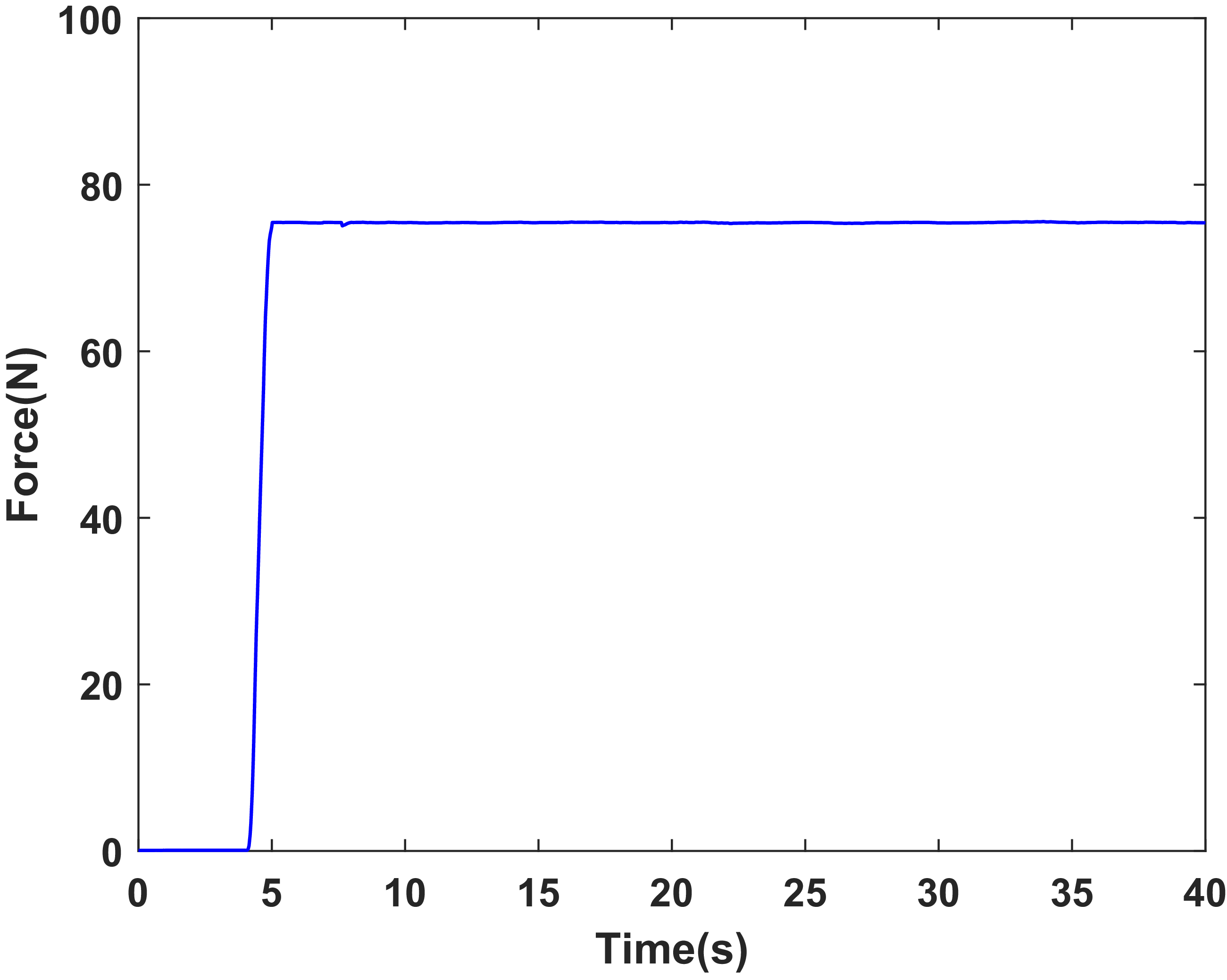
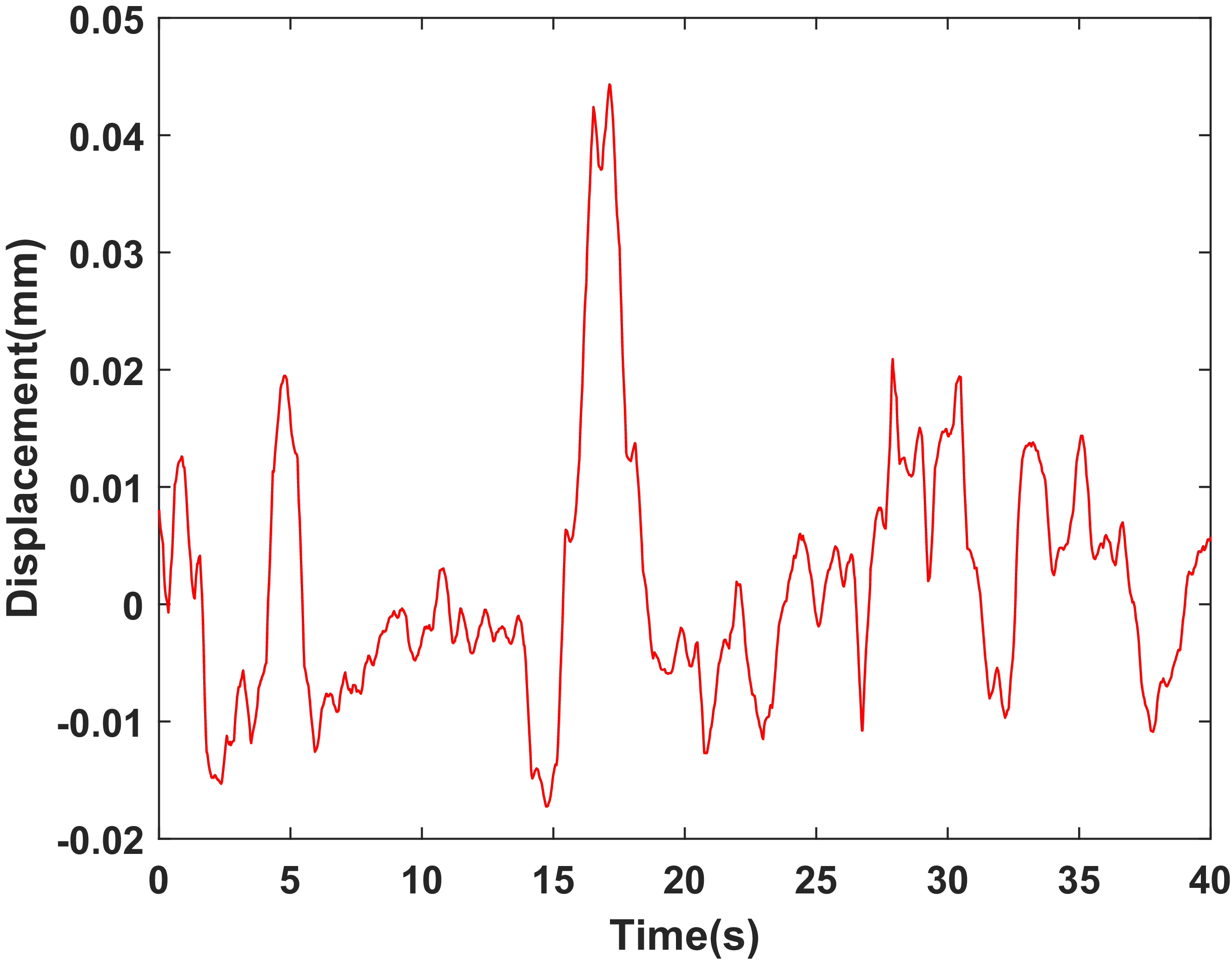
To verify the effect of the locking current, an experiment was conducted under a locking current of 1.5 A. Figure 26 shows the time history of the force acting on the telescopic pole during its motion under this condition. Figure 27 shows the time history of the relative displacement between the outer cylinder of the damper and the micro linear motor during the motion of the telescopic pole under the same condition. As shown in Figure 26, the force signal measured by the force sensor starts to increase after 4 s, reaches a maximum value of 75 n within 1 s, and then remains approximately constant. Figure 27 shows that the maximum displacement between the outer cylinder and the micro linear motor is 0.044 mm. These results indicate that effective locking is achieved and that the active mode of the LMRA is feasible.
Time history of the force acting on the telescopic pole during its motion under 1.5 A current.

Time history of the relative displacement between the outer cylinder of the damper and the micro linear motor under 1.5 A current.

8. Testing of SCMRPK
Figure 28(a) and (b) show the block diagram and photographs of the SCMRPK experimental setup, respectively. The setup consists of a controller (type: YXSPACE-SP6000, Nanjing Yanxun Company), a controlled current source (type: OPA549, Chengdu Yike Company), a sensor unit, a motor driver, and the SCMRPK prototype. The sensor unit includes one micro position sensor and two angle sensors. A micro position sensor (type: PM11-2, linearity: 0.015 mm, Taizhou Quantum Electronic Technology Company) is embedded in the prosthetic shank to measure the relative displacement (Δd) of the piston rod for monitoring the locking status of the LMRA in active mode. Angle sensor AS1 (type: WDD35S2, linearity: 0.1 mm, Shanghai Huiren Company) is coaxially mounted on the hip joint synchronization mechanism (HJSM) to measure the swing angle (θ 1) of the TSM. Angle sensor AS2 (type: GTC, accuracy: 0.022°, Taizhou Quantum Electronic Technology Company) is coaxially mounted on the K 2 axis to measure the angle (θ 2d) between the second link and the vertical direction.
(a) the block diagram and (b) the photograph of the SCMRPK experimental setup.

Figure 28. Long description
Panel A: A block diagram of the SCMRPK experimental setup. The diagram includes components such as HJSM with AS1, TSM, AS2, SCMRPK, AD, controller, DA, controlled current source, linear motor driver, and connections between them. The diagram shows the flow of signals and power in both semi-active and active modes. Panel B: A photograph of the SCMRPK experimental setup. The photograph shows the physical arrangement of the components, including AS1, AS2, controlled current source, linear motor driver, controller, and computer. The photograph also indicates the connections between these components in both semi-active and active modes.
8.1 Semi-active mode experiment
The semi-active mode experiment was conducted using the setup shown in Figure 28. In this mode, the sensor unit transmits the acquired signals to the controller, and the controller governs the SCMRPK according to Eqs. (13), (14), (16), (18), and (20)–(22). The controlled current source then converts the control voltage (U c) generated by the controller into the coil current (I c), as indicated by the red line in Figure 28.
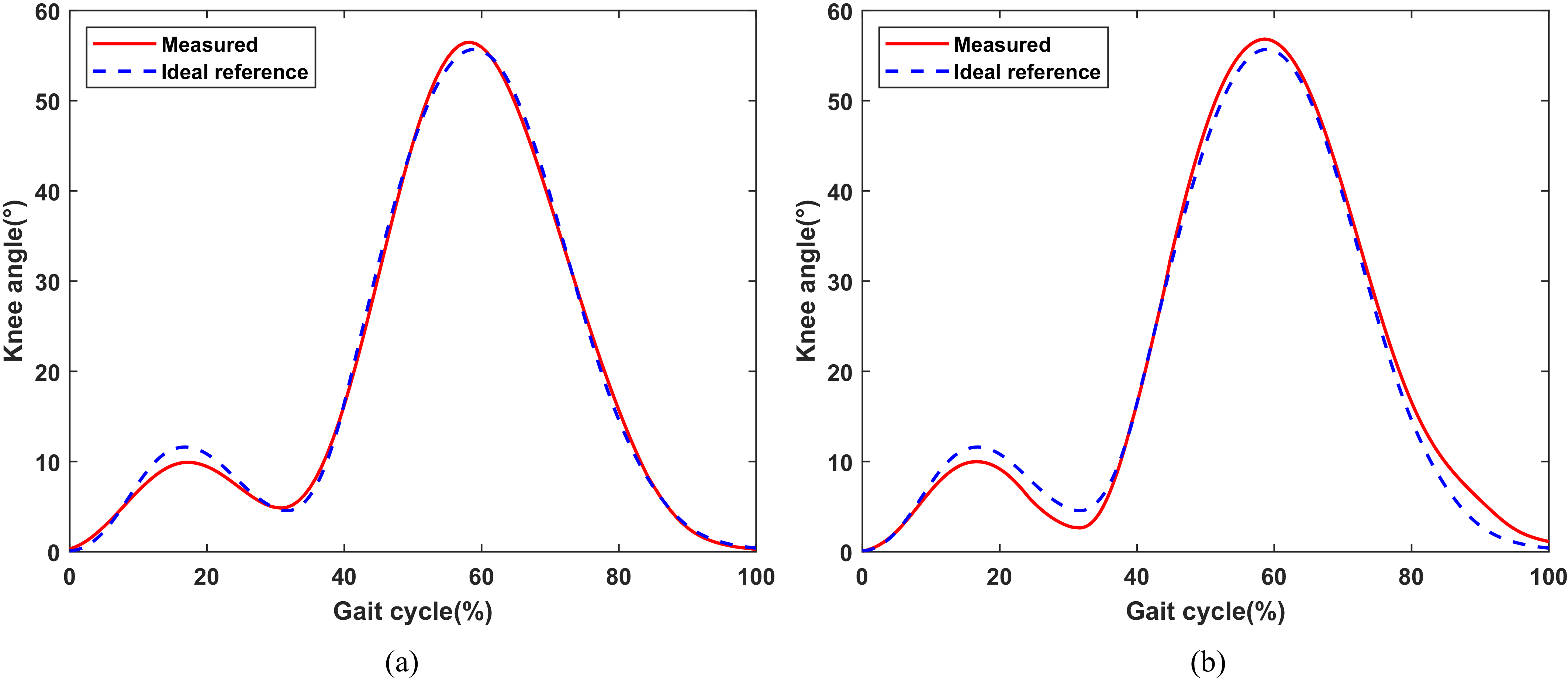
In the experiment, the SCMRPK-based lower limb prosthesis was attached to the subject’s hip through a connector, and its motion was driven by the subject’s thigh swing. Figure 29(a) and (b) show the time histories of the knee joint angle (−θ 4d) under the proposed control algorithm at walking speeds of 0.8 m/s and 1.2 m/s, respectively, in comparison with the reference angle θ d4d (0° to 56°). The results show that, at walking speeds of 0.8 m/s and 1.2 m/s, the knee joint angle ranges from 0.25° to 56.47° and from 0.04° to 56.83°, respectively, which are in good agreement with the reference angle.
Time histories of the measured knee angle (−θ 4d) of the SCMRPK with the controlled current by the algorithm developed in this paper for (a) 0.8 m/s, (b) 1.2 m/s walking speeds and the ideal reference knee angle.

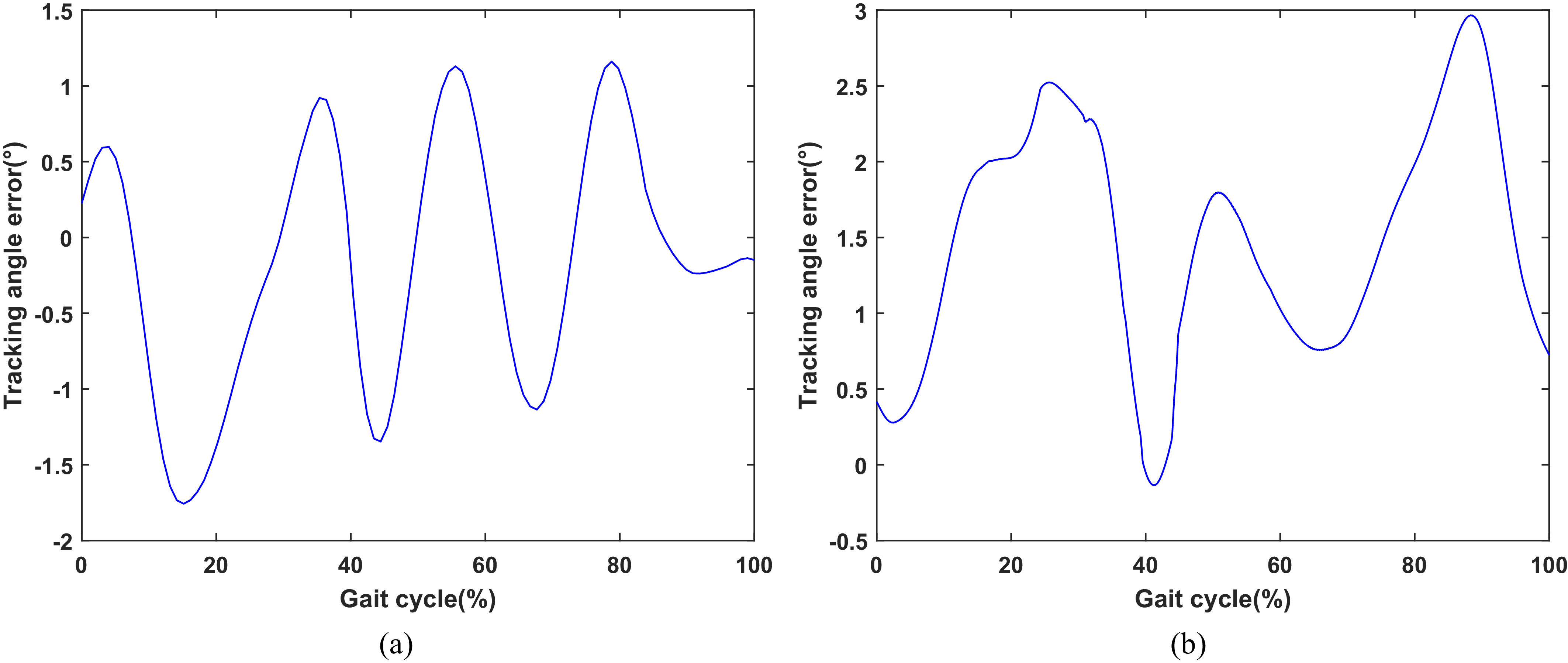
In addition, the time history of the tracking angle error between the measured knee angle (−θ 4d) and the ideal reference knee angle under the control current is shown in Figure 30. Observing Figure 30(a) and (b), at a walking speed of 0.8 m/s, the maximum absolute tracking angle error is 1.76°, the maximum relative tracking angle error is 3.14%, and the root mean square (RMS) error is 0.51°; at a walking speed of 1.2 m/s, the maximum absolute tracking angle error is 2.97°, the maximum relative tracking angle error is 5.31%, and the RMS error is 1.54°.
Time histories of the tracking angle error between the measured knee angle (−θ 4d) of the SCMRPK with the controlled current by the algorithm developed in this paper for (a) 0.8 m/s and (b) 1.2 m/s walking speed and the ideal reference knee angle.

The experimental results show that the proposed control method can effectively reduce the tracking angle error. During the stance phase, stability is mainly ensured by the mechanical characteristics of the four-bar linkage and the user’s self-regulation. Rapid error correction during the swing phase is beneficial to motion coordination. Overall, the SCMRPK can accurately track the reference knee joint angle throughout the entire gait cycle.
8.2 Active mode experiment
The experimental setup is shown in Figure 28. Compared with the semi-active mode, the active mode additionally involves motor-driver control. The sensor unit transmits the acquired signals to the controller. According to the control method established in Section 6.2, θ 2d is regulated to control the knee joint angle θ 4d.
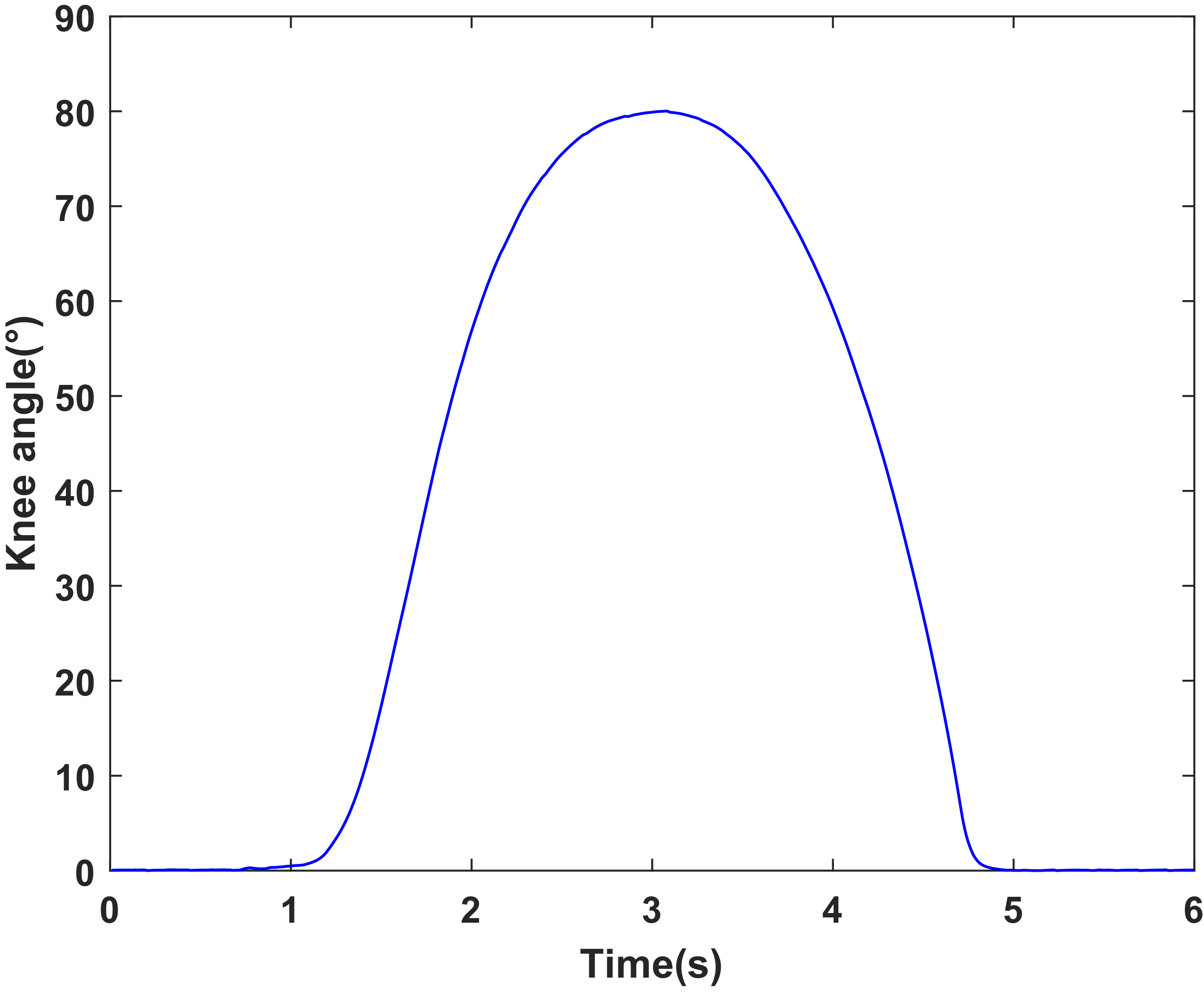
During obstacle-crossing experiments, the controller instructs the SCMRPK to generate a large knee flexion angle to assist the test subject in crossing the obstacle. Figure 31 shows the motion process of the lower limb prosthesis crossing a 0.3 m obstacle under active control. Figure 32 shows the time history of the measured knee angle (−θ 4d) of the SCMRPK under the current controlled by the algorithm developed in this paper during the obstacle-crossing process. The obstacle-crossing process can be divided into three stages. First, a locking current is applied so that the damper forms an approximately rigid connection. Then, the motor drives the knee joint to flex to about 80°. Finally, after the obstacle is crossed, the motor drives the knee joint to extend, thereby completing the obstacle-crossing motion.
The motion process of the lower limb prosthesis while crossing an obstacle under active control.

Time history of the measured knee angle (−θ 4d) of the SCMRPK under the current controlled by the algorithm developed in this paper during the obstacle-crossing process.

In summary, the semi-active mode of the SCMRPK can be achieved by controlling the damping force of the MR damper. When the load force is smaller than the damping force, the active mode of the SCMRPK can adjust the flexion angle by adjusting the displacement of the motor telescopic pole. The test results show that the proposed SCMRPK can operate effectively in both semi-active and active modes.
9. Conclusion
This paper presents a systematic study on the structural design, magnetic circuit design, dynamic modeling, control methods, and experimental validation of the SCMRPK. The main conclusions are as follows:
-
1. A structurally compact magnetorheological prosthetic knee joint with obstacle-crossing function, namely the SCMRPK, was designed. The SCMRPK is formed by combining a four-bar linkage mechanism and a LMRA. By integrating a micro linear motor into the piston rod of an MR damper, the LMRA combines the active mode and the semi-active mode, enabling it to output driving force in the active mode and controllable damping force in the semi-active mode. Under dimensional constraints, the SCMRPK combines bionic rotational characteristics, semi-active damping regulation capability, and active driving capability.
-
2. A key dimensional design method for the LMRA magnetic circuit was proposed. Simulation analysis and experimental testing were carried out on the magnetic circuit of the LMRA with the integrated micro linear motor, and the results verified the effectiveness of the designed magnetic circuit.
-
3. The kinematic and dynamic models of the SCMRPK-based lower limb prosthesis were established, and the control methods for the semi-active mode and the active mode were designed.
-
4. A displacement tracking test was carried out for the LMRA in active mode. The results show that, under a locking current of 1.5 A, the telescopic pole can achieve stable displacement tracking, which verifies the feasibility of the active mode of the LMRA.
-
5. Semi-active gait experiments and active obstacle-crossing experiments of the SCMRPK were completed. The semi-active experimental results show that, at a walking speed of 1.2 m/s, the root mean square error between the measured knee angle of the SCMRPK and the ideal knee angle is 1.54°. The active experimental results show that the SCMRPK-based lower limb prosthesis can cross an obstacle with a height of about 0.3 m.
In summary, the proposed SCMRPK is not only compact in structure but also enables a relatively natural gait and obstacle crossing.
Author contributions
Lei Xu was responsible for the research conception and system design. Lei Xu and Chao Wang contributed to the manuscript writing and revision. Qiuxia Fan and Qianqian Zhang were responsible for the research methodology and project supervision. Lei Xu, Chao Wang, and Yuhui Liu participated in the experimental validation, data processing, and analysis.
Financial support
This research was funded in part by the Fundamental Research Program of Shanxi Province (No. 202403021211212), the Postdoctoral Fellowship Program and China Postdoctoral Science Foundation (No. 2025M774384), the Key Country Science and Technology Cooperation Project under the Shanxi Provincial Science and Technology Cooperation and Exchange Special Program (Grant No. 202304041101007), and the National Key Research and Development Program of China—Sub-project on Integration Technology of Laser Interferometry System and Inertial Sensors (Grant No. 2024YFC2207100).
Competing interests
The authors declare no conflicts of interest.
Ethical approval
Not applicable.
Use of AI
AI tools were not used in the research or writing of this paper.









 τy