
I. INTRODUCTION
The most widely used austenitic stainless steels are those of the AISI 300 series, i.e., Fe–C–Cr–Ni alloys containing approximately 18 wt% Cr and 8 wt% Ni with a very low carbon content <0.08 wt%. Reference Leuk Lai, Lo and Shek1,Reference Marshall2 The chemical composition not only influences the mechanical properties, formability, passivity but also significantly affects the stability of the face centered cubic austenitic microstructure. Hence, the paramagnetic austenite can transform due to plastic deformation to a more stable microstructure, i.e., paramagnetic ε-martenisite and/or ferromagnetic α′-martensite. Reference Martin, Wolf, Martin, Kruger and Rafaja3–Reference Man, Kubena, Smaga, Man, Jaevenpaa, Weidner, Chlup and Polak9 Consequently, in the AISI 300 series, several austenitic steels are metastable, e.g. AISI 304, 321, 348, or 316L Reference Smaga, Walther and Eifler5–Reference Man, Kubena, Smaga, Man, Jaevenpaa, Weidner, Chlup and Polak9 and intensive investigations of monotonic-induced and cyclic-induced phase transformations as well as their influences on monotonic and cyclic strength were performed. According to their excellent mechanical and technological properties as well as corrosion resistance, austenitic Cr–Ni steels are widely used for components in nuclear power and chemical plants as well as in a big variety of industrial, architectonic and biological applications. Reference Leuk Lai, Lo and Shek1,Reference Marshall2,Reference Lo, Shek and Lai10 Therefore, improvement of fatigue properties of these steels is required. Since fatigue damage generally initiates at the surface, Reference Mughrabi11,Reference Man and Polák12 improved surface treatments and finishing processes are continuously developed. In this context, investigations on e.g. cryogenic laser shot peening, Reference Ye, Suslov, Lin and Cheng13 surface mechanical attrition treatment Reference Zhang, Hei, Liu, Lu and Lu14 and cryogenic deep rolling Reference Meyer15 were performed. Using a low-temperature turning process with carbon dioxide snow as cooling medium in the cutting zone, a variation of the morphology at the specimen surface can be realized, Reference Aurich, Mayer, Kirsch, Eifler, Smaga and Skorupski16–Reference Mayer, Skorupski, Smaga, Eifler and Aurich18 which allows net shape machining with simultaneous formation of martensitic layers. In this context, the present paper focuses on the influence of microstructure on the cyclic deformation behavior of metastable austenitic stainless steel AISI 347 with different surface morphologies.
II. INVESTIGATED MATERIAL AND EXPERIMENTAL PROCEDURES
The investigated material was the metastable austenitic stainless steel AISI 347 (X6CrNiNb1810, 1.4550) delivered as rolled steel bars with a diameter of 25 mm, in solution annealed state from one single batch. To obtain a fully austenitic microstructure, an additional solution annealing at 1050 °C for 35 min followed by quenching in helium atmosphere was performed in an industrial heat treatment furnace. After this solution annealing heat treatment, the material has a mean grain size of 17 µm. The chemical composition has a fundamental influence on austenite stability, which can be described by the α′-martensite start temperature M S for thermally induced α′-martensite formation and with the so-called M d30 temperature for plasticity-induced α′-martensite formation, respectively. By definition, 50 vol% α′-martensite are formed as a result of 30% plastic deformation at M d30. As discussed in the literature, Reference Marshall2,Reference Martin, Fabrichnaya and Rafaja19 all alloying elements in austenitic steels reduce the M S and the M d30 temperatures. Several empirical equations Reference Becker, Brandis and Küppers20 have been derived for M S and M d30. Note that decreasing M S and M d30 temperatures correspond to an increasing austenite stability. Furthermore, by additional alloying with niobium at a content of approx. ten times the carbon concentration (in mass%), the formation of chromium carbides which can result in chromium depletion at the grain boundaries and, hence, promote intergranular corrosion is reduced since Nb carbides are formed instead of Cr carbides which would decrease the soluted Cr-content in the austenite crystals. The chemical composition of the investigated AISI 347 steel batch is given in Table I including the characteristic parameters of metastabilty, i.e., M S and M d30 temperatures, calculated according to the empirical equations given by Eichelmann Reference Eichelmann and Hull21 and Angel, Reference Angel22 respectively.
Chemical composition of AISI 347 in wt% and M S, M d30 temperatures.

To investigate the cyclic deformation behavior and deformation-induced α′-martensite formation in the high cycle fatigue (HCF) regime, reference specimens with a gauge length of 15 mm and diameter of 7.6 mm were conventionally turned. During this process, no martensite formation occurred. These specimens with austenitic surface layer were polished mechanically and electrolytically (ASLp) to eliminate turning induced surface roughness. A very flat surface with maximum height of profile R z = 0.7 µm was obtained for this specimen variant. During polishing, a layer of 25–35 µm thickness was removed. Hence, the diameter of each mechanically and electrolytically polished specimen was measured using an optical system with a resolution of 1 µm before fatigue testing. The influence of surface morphology on cyclic deformation behavior was investigated using specimens produced with four different manufacturing parameter sets: (i) reference specimen ASLp as described above, (ii) specimen manufactured with cutting speed v c = 30 m/min, cutting depth a p = 0.2 mm, and cutting feed f = 0.15 mm/rev without CO2 snow cooling and, consequently, with austenitic surface layer after turning (ASLt), (iii) specimen after cryogenic turning with the same parameters but using a CO2 snow cooling system and hence featuring a martensitic surface layer (MSLt), and (iv) specimen type MSLt, after additional mechanical and electrolytical polishing (MSLp). More details about the cryogenic turning process are published elsewhere. Reference Aurich, Mayer, Kirsch, Eifler, Smaga and Skorupski16–Reference Mayer, Skorupski, Smaga, Eifler and Aurich18
Monotonic loading of specimens with fully austenitic microstructure and with max. content of α′-martensite 98 vol% was performed at ambient temperature. Specimens with maximum achievable α′-martensite were prepared by cyclic loading at T = −60 °C in load increase tests (LITs) up to a number of cycles N l = 45 with a load ratio of R = −0.5 and a frequency of 0.05 Hz using the same testing device. The LIT started with a maximum stress σmax = 200 MPa followed by an increase in σmax of 100 MPa up to 1000 MPa each 5 load cycles. Stress-controlled single step tests in the HCF regime up to an ultimate number of cycles N U = 2 × 10⁶ were performed on a servohydraulic testing system MTS 810 with a load ratio of R = −1, a frequency of 5 Hz, and triangular waveform at ambient temperature. Mechanical stress–strain hysteresis, temperature, electrical resistance, and magnetic Feritscope™ measurements were used for detailed characterization of the cyclic deformation behavior and deformation-induced α′-martensite formation. In this article, data from σ–ε-hystereses converted into cyclic deformation curves and Feritscope™ measurements are shown and discussed. The Feritscope™ magnetic fraction (ξ) is given in volume percent ferrite (FE%), without converting into α′-martensite content. In the literature, a linear correlation between FE% and α′-martensite content is reported. Reference Talonen, Aspegren and Hänninen23
To determine the stability of γ-austenite by measuring the martensite start temperature (M S), in situ X-ray diffraction measurements during cooling were performed with Cu-Kα-radiation at 40 kV and 40 mA in an Empyrean type diffractometer. For this test, a cryogenic chamber ANTON PAAR TTK 450 (Anton Paar GmbH, Graz, Austria) with min. temperature of −193 °C was used. Quantitative analysis of the X-ray diffraction patterns was carried out by the Rietveld method. Reference Bish and Howard24 To minimize the influence of texture, the diffraction profiles were measured at five different tilt angles in the range 0° ≤ χ ≤ 40° with relative errors in the quantification of the phase contents of about 1–3% for each phase. Optical micrographs were taken with a Leica DM 6000M microscope (Leica Microsystems, Wetzlar, Germany). For detailed characterization of grain orientations and phase analysis, a scanning electron microscope FEI Quanta 600 FEG (FEI Munich GmbH, Munich, Germany) including electron backscatter diffraction (EBSD) was used. Further scanning electron microscopic investigations were made after focused ion beam (FIB) preparation obtained at the Nano Structuring Center (NSC) of TU Kaiserslautern using a FEI Helios Nanolab 650 dual-beam FIB (FEI Munich GmbH, Munich, Germany). To exclude FIB-induced austenite-martensite phase transformation, Reference Basa, Thaulow and Barnoush25 cutting and polishing parameters were optimized in a parameter study at fully austenitic microstructures combined with EBSD investigations of the phase composition after FIB milling. Reference Skorupski26 Microhardness measurements were performed with a computer-controlled Fischerscope H100C system (Fischer Technology, Windsor, Connecticut) using a Vickers indenter with a force of 100 mN and a load time of 10 s.
III. RESULTS AND DISCUSSION
A. Surface morphology
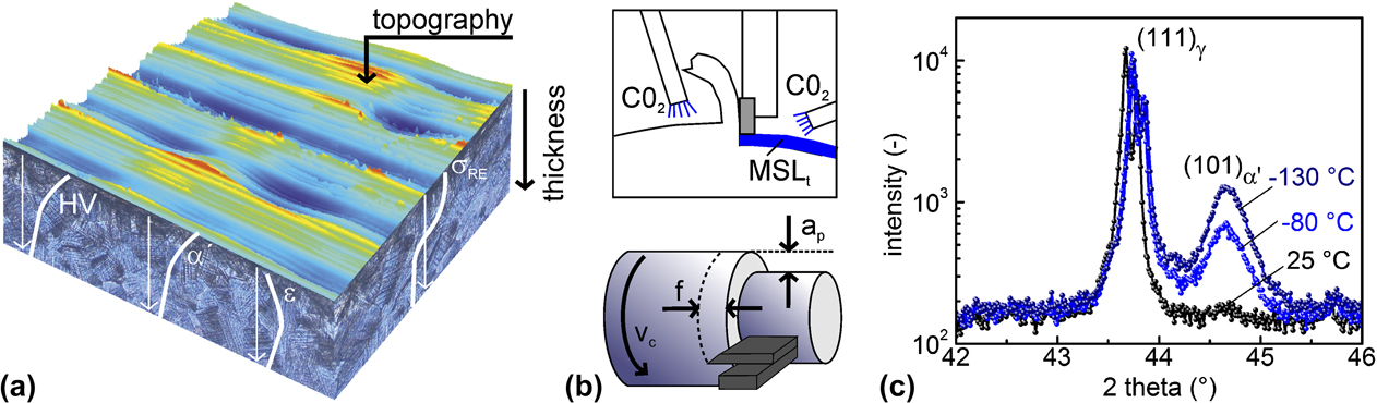
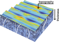
Surface morphology [Fig. 1(a)] includes topography and microstructural features underneath the surface as well as residual stress state. During cryogenic turning of metastable austenitic stainless steels, the near-surface region transforms from austenite into α′-martensite and/or ε-martensite. A variation in the morphology can be realized by turning process parameters [Fig. 1(b)] using carbon dioxide snow as cooling medium to achieve sufficiently low temperatures in the cutting zone. Reference Mayer, Kirsch and Aurich17 In the case of metastable austenitic stainless steels, this technology allows the net shape machining with simultaneous formation of martensitic layers at the specimen surface, when the process temperature is lower than the martensite deformation temperature (M d30 = 46 °C, see Table I). Generally, during the turning process, the contact zone between workpiece and tool as well as the temperature in the surface layer cannot be monitored directly. Instead, the workpiece surface temperature in the heat affected workpiece zone after a 3/4 rotation was measured in situ during turning. For the investigated AISI 347 turned with f = 0.15 mm/rev, temperatures below room temperature were measured. Reference Mayer, Kirsch and Aurich17
Schematic representation of surface morphology (a) and cryogenic turning process (b) as well as X-ray diffraction spectra from in situ cooling test (c).

Metastability of austenites is usually described in terms of martensite start temperature M S or M d30 temperature (see Table I). For the investigated material, the M S-temperature was determined experimentally by in situ X-ray diffraction measurements during cooling. Figure 1(c) shows selected X-ray diffraction patterns measured at T = 25, −80, and −130 °C. At 25 °C, an austenite (111) peak with relatively small width can be clearly seen in the initial solution annealed microstructure. During cooling, at T = −80 °C a first (101) α′-martensite peak was measured, i.e., this temperature is, in good accordance with the calculated M S-value shown in Table I, identified as the temperature for the onset of thermally induced α′-martensite formation. Further temperature decrease effects a small increase of the intensity of the (101) α′-martensite peak, indicating ongoing α′-martensite formation. However, a still high content of retained austenite existed and, hence, mechanical deformation is required to obtain higher martensite fractions.
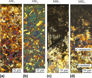
Figure 2 shows optical micrographs of the near-surface microstructure of four morphologies in longitudinal sections. It is clearly seen that only in case of CO2, snow cooling martensite was formed. Detailed X-ray investigations directly at the turned surface and after electrochemical removing of thin material layers from specimens surface provide that microstructure consists of γ-austenite, α′-martensite and/or ε-martensite while after conventional turning γ-austenite is the only microstructural constituent. Independent from the turning processes, all specimens show relatively high tensile residual stresses in the range of 800 MPa at the surface. Due to varied process parameters, the depth of the phase transformation is in the range of 200–300 µm. For more details, see Refs. Reference Aurich, Mayer, Kirsch, Eifler, Smaga and Skorupski16, Reference Skorupski26, and Reference Smaga, Skorupski, Boemke, Mayer, Kirsch, Aurich, Raid, Seewig, Man, Eifler and Beck27.
Optical micrographs of near surface microstructure of four investigated morphologies, after color etching using Beraha I etchant.

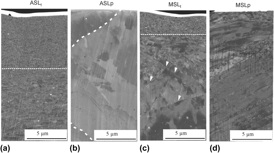
To study the effect of subsurface microstructure on fatigue in more detail, scanning electron microscopy investigations on specimens after FIB preparation as well as fractography were performed. Figure 3 summarizes FIB longitudinal sections of the near-surface microstructure of the four investigated specimen variants. The ASLt specimen shows a highly deformed nanocrystalline surface layer with a thickness up to 8 µm. From literature, it is known Reference Kumagai, Akita, Itano, Imafuku and Ohya28–Reference Altenberger, Scholtes, Martin and Oettel31 that deformation-induced nanocrystalline surface layers reduce plastic strain amplitude and can improve fatigue life. Due to mechanical and electrolytical polishing, this layer was removed and an unaffected austenitic microstructure is seen in Fig. 3(b) for the variant ASLp. Hence, the nanocrystalline layer in ASLt is concluded to be responsible for the smaller plastic strain amplitude in the initial fatigue state [Fig. 6(a)]. Similar results were found in metastable austenitic stainless steel AISI 304 after shot peening and deep rolling at ambient temperature. Reference Altenberger, Scholtes, Martin and Oettel31 Due to these processes, a complex near-surface microstructure with highly deformed nanocrystalline microstructure, twins and α′-martensite was produced. In our study, turning with relatively high passive forces caused by low cutting speed (v c = 30 m/min), low cutting depth (a p = 0.2 mm), a feed of f = 0.15 mm/rev, and chamfered cutting edge (CNMA120416T02020) with negative orthogonal rake angle of −6° and cutting edge inclination of −6° was performed for the final external cylindrical turning. Reference Aurich, Mayer, Kirsch, Eifler, Smaga and Skorupski16–Reference Mayer, Skorupski, Smaga, Eifler and Aurich18 These parameter sets led in all cases to the formation of a nanocrystalline near-surface microstructure, but in case of turning without CO2 snow cooling, no α′-martensite and no twins are formed contrary to shot peening and deep rolling processes. In the case of MSLt surface layer, besides a nanocrystalline layer, nanotwins and/or martensite, which was confirmed in X-ray investigations, Reference Skorupski26,Reference Smaga, Skorupski, Boemke, Mayer, Kirsch, Aurich, Raid, Seewig, Man, Eifler and Beck27 can be seen. After mechanical and electrolytical polishing (MSLp) of the cryogenically turned specimen, the near-surface microstructure contains mainly austenite and martensite [Fig. 3(d)]. Because the martensitic surface layer remained nearly unaffected by polishing and only the nanocrystalline layer was almost removed, it is concluded that the martensitic surface layer reduced cyclic plastic deformation during the softening phase of cyclic loading, resulting in similar εa,p values for both MSL specimen (MSLp and MSLt), see Fig. 6(a).
Near-surface microstructure of the four investigated specimen variants, scanning electron microscopy (SEM) micrographs using ion contras.

B. Mechanical properties of γ-austenite and α′-martensite
Since the near-surface microstructure of cryogenic turned metastable austenitic steel specimen consists of austenite and martensite, the monotonic properties as well as hardness of theses phases are important. Therefore, monotonic deformation behavior of (i) a “γ-specimen” in solution annealed state (1050 °C/35 min/He) and, hence, with fully austenitic microstructure before tensile loading and (ii) an “α′-specimen” with high α′-martensite content obtained in a LIT at −60 °C (see previous section) were investigated in tensile tests. Besides stress and strain, magnetic permeability was measured in situ at the γ-specimen using a Feritscope™ device to characterize deformation-induced α′-martensite formation. Ex situ Feritscope™ measurements on the α′-specimen showed 48 FE% before tensile loading. Quantitative phase analysis of the respective X-ray diffraction spectrum yielded 90 vol% of α′-martensite, 1 vol% of ε-martensite, and 9 vol% of retained austenite.
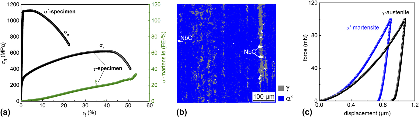
Figure 4 summarizes the results of the tensile and microhardness tests. An ultimate tensile strength of 621 MPa and an elongation at fracture of 51% were measured for the γ-specimen. α′-martensite formation in this specimen started at the onset of macroscopic plastic deformation and increased continuously up to 33 FE% (56 vol%) at specimen failure. Comparison of stress–strain curves from both specimens [see Fig. 4(a)] shows a significant increase in both yield stress (factor 5) and ultimate tensile strength (factor 2) of the α′-compared to the γ-specimen and a reduction of elongation at fracture from 51 to 22%. For detailed characterization of microhardness and accordingly, strength of the γ- and α′-phase, microhardness tests were performed on a longitudinal section of an “α′-specimen”, i.e., after cyclic LIT at T = −60 °C. Figure 4(b) shows the EBSD-phase analysis of the area, where the indentations in both phases were performed. The area fraction of 90% α′-martensite correlates well with the α′-martensite contents measured by X-ray diffraction (90 vol%). Additionally, Fig. 4(b) reveals some niobium carbides (white areas) in both phases. The plastically deformed γ-austenite has a microhardness of 342 ± 23 HV0.01. Taking the microhardness of the non-deformed γ-austenite in solution annealed state of 252 ± 19 HV0.01 as a reference, an increase of about 36% is observed, which is attributed to an increase of dislocation density in the austenite during the previous cyclic deformation. As expected, the α′-martensite is, with an average microhardness of 476 ± 15 HV0.01, the harder one of both phases. However, this value is significantly smaller than the microhardness of typical thermally hardened steels in the fully martensitic state, e.g., martensitically hardened AISI 1045 with 750 HV0.01. The achievable microhardness essentially depends on the carbon content, which is, with 0.024%, very low in the investigated AISI 347 steel. As a result, the b.c.c. lattice structure is not tetragonally distorted during the γ–α′ phase transformation. Consequently, the deformation-induced α′-martensite in metastable austenitic stainless steels has a very high strength combined with still considerable ductility [see Fig. 4(a)]. These findings correlate well with the force–displacement curves shown in Fig. 4(c).
Stress–strain curves of α′-specimen and γ-specimen with development of α′-martensite content in the γ-specimen during tensile test (a), EBSD-phase analysis (b), force–displacement curves of γ-austenite and α′-martensite (c).

C. Cyclic deformation behavior and α′-martensite formation
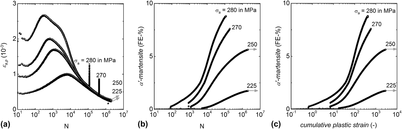
To characterize the cyclic deformation behavior of the investigated metastable austenitic stainless steel AISI 347 in the HCF regime, specimens with reference surfaces ASLp were cyclically loaded in stress-controlled single step tests with stress amplitudes in the range 225 MPa ≤ σa ≤ 280 MPa. The development of cyclic deformation-induced α′-martensite formation was measured in situ by a Feritscope™ magnetic sensor. In Fig. 5(a), the resulting developments of plastic strain amplitude εa,p are plotted versus the number of cycles N. The εa,p, N curves illustrate pronounced cyclic hardening after a short period of initial cyclic softening. The cyclic hardening is caused by an increase in dislocation Reference Bassler and Eifler32,Reference Sorich, Smaga and Eifler33 and stacking fault density, Reference Hahnenberger, Smaga and Eifler8,Reference Bayerlein, Christ and Mughrabi34 as well as by formation of deformation-induced α′-martensite [Fig. 5(b)]. Note that in stress-controlled fatigue tests cyclic hardening leads to a decrease in plastic strain amplitude at constant stress amplitude resulting in higher fatigue life compared to cyclic neutral or softening behavior. In total- or plastic strain-controlled fatigue tests, cyclic hardening leads to significant increase of stress amplitude, in certain cases even higher than the ultimate tensile strength, and consequently metastable austenite with low austenite stability may achieve a smaller number of cycles to failure compared to austenites with higher stability. A positive influence of α′-martensite formation on fatigue life is observed in the present case, i.e. stress-controlled fatigue tests in which austenite-martensite transformation causes hardening, which reduces plastic strain amplitude by a factor of 2 and more. It should be noted in this context that during both tests, which reached the ultimate number of cycles (2 × 10⁶), significant cyclic plasticity occurs in an intermediate stage of the test which is reduced by α′-martensite formation induced cyclic hardening to such low values that no fatigue failure occurred. Figure 5(b) shows the development of α′-martensite content during the fatigue tests discussed above. After an incubation period that depends on stress amplitude, the α′-martensite fraction increases continuously with number of cycles. With increasing stress amplitude, the onset of α′-martensite formation is shifted to lower N and higher α′-martensite fractions are measured at specimen failure. For a comprehensive analysis of cyclically induced α′-martensite formation, a plot of α′-martensite versus cumulative plastic strain is used. The cumulative plastic strain λ can be estimated from εa,p, N curves according to Eq. (1):
 $$\lambda = 4 \cdot \int_{N = 1}^{N = {N_{\rm{f}}}} {{\varepsilon _{{\rm{a,p}}}}{\rm{d}}N} \quad .$$
Development of plastic strain amplitude εa,p (a) and α′-martensite fraction (b) as versus number of cycles N, α′-martensite fraction ξ versus cumulative plastic strain λ (c).

Figure 5(c) shows the development of α′-martensite content versus cumulative plastic strain. An increasing stress amplitude σa causes higher α′-martensite fractions (ξ) for identical λ. The development of α′-martensite content in stress-controlled tests is comparable to the results given in Ref. Reference Angel22 as well as for plastic- and total-strain-controlled fatigue tests shown in Refs. Reference Smaga, Walther and Eifler5 and Reference Hahnenberger, Smaga and Eifler8. However, with 1.8 FE% < ξ < 8.8 FE% the maximum values of α′-martensite fraction at specimen failure/ultimate number of cycles is significantly smaller compared to plastic- and total-strain-controlled low cycle fatigue (LCF) tests. Reference Smaga, Walther and Eifler5,Reference Skorupski26,Reference Skorupski, Smaga and Eifler35 From the ξ, λ-curves in Fig. 5(c), the rate of α′-martensite formation dξ/dλ can be derived. dξ/dλ is zero at the beginning of each test, then increases to a maximum and decreases again toward the end of the test.
D. Influences of surface morphology on cyclic deformation behavior
Because surface morphology strongly affects fatigue behavior, especially in the HCF regime, its influence on cyclic deformation and lifetime behavior of the investigated metastable austenitic steel was considered in detail. A stress amplitude of 270 MPa was chosen for the reference state, i.e. polished austenitic surface layer (ASLp), see Fig. 5(a).
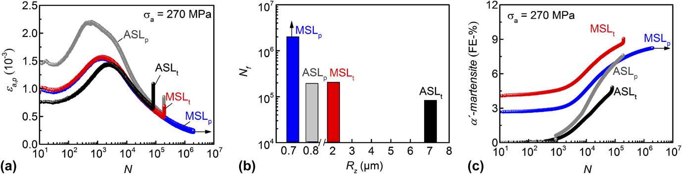
Figure 6(a) shows cyclic deformation curves of specimens with the four investigated surface morphologies. As mentioned in the section “surface morphology” after cryogenic turning, the near-surface microstructure consists of γ-austenite, α′-martensite, and ε-martensite while after conventional turning, γ-austenite is the only microstructural constituent. All specimens show relatively high tensile residual stresses. Reference Smaga, Skorupski, Boemke, Mayer, Kirsch, Aurich, Raid, Seewig, Man, Eifler and Beck27 Besides phase distribution and residual stresses, a further important factor influencing fatigue life is topography. Figure 6(b) shows the number of cycles to failure as a function of maximum profile height R z measured by confocal microscopy. As expected, the polished reference specimens with MSLp and without martensite ASLp have a similar flat surface (R z < 0.8 μm) while considerable roughness is seen in the as-turned specimens. On this background, the benefit of a martensitic surface layer on fatigue properties can be clearly seen: The MSLp specimen even achieved the ultimate number of cycles N U = 2 × 10⁶ without failure while the ASLp specimen with similar surface roughness [see Fig. 6(b)], but turned without CO2 snow cooling, i.e. with pure austenitic microstructure, failed at N = 2 × 10⁵. Furthermore, an increase in R z by a factor of 3 for the MSLt compared to the ASLp specimen had no significant influence on fatigue life and both specimens achieved N f > 105. Therefore, the negative influence of surface roughness on fatigue life can be compensated by martensitic surface layers. In interrupted total-strain-controlled fatigue tests, scanning electron microscopy (SEM) investigations of ASLp and MSLp specimens showed clear differences in the fatigue induced deformation marks at the specimen surface. Reference Skorupski, Smaga and Eifler35 While in ASLp, specimens even in an early state of fatigue a large number of slip bands was detected from which microcracks were initiated, the same number of cycles did not cause any change in the surface topography of the MSLp specimens, and crack formation occurred at surface defects, mostly inclusions. For details see Refs. Reference Skorupski26 and Reference Skorupski, Smaga and Eifler35. The εa,p, N curves for all surface morphologies [Fig. 6(a)] show after initial cyclic softening up to N ≈ 1000, cyclic hardening, mainly induced by plastic deformation-induced α′-martensite formation [Fig. 6(c)]. Interestingly, the highest initial and peak value of εa,p was measured for the ASLp specimen. In contrast to that, the smallest value of εa,p at the beginning of the test and during the cyclic softening period were measured for the ASLt specimen. Note that both specimen conditions with martensitic surface layer showed similar εa,p, N curves between that of ASLp and ASLt specimens. It’s further worth noting that cyclic hardening toward the end of the tests yields similar plastic strain amplitudes for all specimen variants irrespective of surface morphology, indicating that cyclic hardening is dominated by α′-martensite formation in the specimen volume while damage processes are strongly affected by surface morphology.
Development of the plastic strain amplitude εa,p as function of number of cycles N (a), number of cycles to failure N f as a function of maximum height of profile R z (b), and development of the α′-martensite fraction as function of number of cycles N (c) for specimens with four different surface morphologies.

E. Scanning electron microscopy investigations
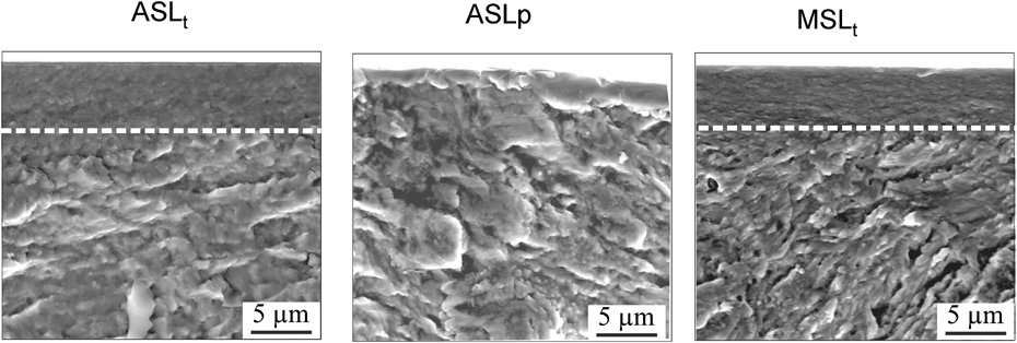
Figure 7 shows scanning electron microscopy images of fracture surfaces of ASLt, ASLp, and MSLt specimens. Note that the MSLp specimen achieved the ultimate number of cycles of 2 × 10⁶ without failure. The fracture surfaces indicate strong deformation in a surface layer with about 5 µm thickness, which corresponds to the thickness of the nanocrystalline layers visible in Figs. 3(a) and 3(c) for the specimens turned with and without CO2 snow cooling (ASLt and MSLt). Contrary to that, the ASLp specimen where the nanocrystalline layer was removed by mechanical and electrolytical polishing shows no signs of localized plastic deformation near the surface. Note that, in spite of these indications of enhanced local plasticity in the nanocrystalline surface layer, the overall plastic strain amplitude in the initial phase of fatigue loading is smaller for the ASLt compared to the ASLp specimen [see Fig. 6(a)]. Moreover, fatigue life is, in spite of the distinctly higher roughness of the ASLt specimen, similar for both surface morphologies [see Fig. 6(b)], indicating a positive influence of turning induced surface modification, i.e. the nanocrystalline layer. This interpretation is underpinned by results obtained from HCF tests at 300 °C performed at ASLt and ASLp specimens published in Ref. Reference Smaga, Skorupski, Boemke, Mayer, Kirsch, Aurich, Raid, Seewig, Man, Eifler and Beck27 where no cyclic hardening due to α′-martensite formation in the specimen volume occurs and, hence, the effect of the nanocrystalline surface layer which also remains stable at this temperature is more prominent. Smaller plastic strain amplitudes over the whole lifetime and, despite higher surface roughness, even slightly longer distinctly fatigue life are observed for the ASLt specimen at T = 300 °C.
Fracture surfaces of specimens with different surface morphologies.

The stability of the nanocrystalline surface layer against cyclic deformation-induced phase transformation was investigated by X-ray diffraction. Table II summarizes the changes in α′-martensite content at the surface of all four specimen morphologies during the fatigue tests described in detail above. It can be seen, that only in mechanically and electrolytically polished surfaces, i.e., without nanocrystalline subsurface layer, α′-martensite formation takes place during cyclic loading which appears, as expected, more pronounced in the ASLp specimens. In both as-turned surface layers (ASLt and MSLt) no deformation-induced austenite-martensite transformation occurred, indicating the high stability of the nanocrystalline layers visible in Figs. 3(a) and 3(c).
Change in α′-martensite fraction during cyclic loading from N = 0 to N = 90% N f in the near-surface of four specimen morphologies.

IV. CONCLUSION
The metastable austenitic steel AISI 347 is prone to phase transformation from paramagnetic austenite to ferromagnetic α′-martensite under monotonic and cyclic loading. This phase transformation can be induced in the near-surface region by cryogenic turning with appropriate parameters. Cyclic deformation behavior of the investigated metastable austenitic stainless steel AISI 347 in stress-controlled high cycle fatigue tests at ambient temperature is characterized by initial cyclic softening followed by pronounced cyclic hardening mainly caused by deformation-induced α′-martensite formation.
Using CO2 snow-cooling, a martensitic layer at the specimen surface was produced. Specimens with four different surface morphologies, i.e., conventionally turned, cryogenically turned, and both turned variants after mechanical and electrolytical polishing, were cyclically loaded with a stress amplitude of 270 MPa to investigate the influences of the surface morphology on fatigue behavior. A direct comparison of the fatigue life of two types of polished specimens with very flat topography, both, with and without a martensitic surface layer, showed, that the specimen with a martensitic surface layer reached 2 × 10⁶ cycles without failure, while the purely austenitic specimen failed already at N f = 2 × 10⁵ cycles. Furthermore, cyclic loading of the specimen with martensitic surface layer and austenitic surface layer that were not mechanically and electrolytically polished led to a smaller plastic strain amplitude value in comparison to the austenitic specimen with mechanically and electrolytically polished surface. SEM investigations of the near-surface microstructure showed the development of nanocrystalline layers, which besides the martensitic surface layer, reduced plastic strain amplitude during cyclic loading. The nanocrystalline layers proved to be stable during cyclic loading and, at least partially, compensate the detrimental influence of turning induced surface roughness on fatigue life.
ACKNOWLEDGMENTS
The authors thank the German Research Foundation (DFG) for the financial support within the CRC 926 “Microscale Morphology of Component Surfaces”. The fatigue specimens were turned at the Institute for Manufacturing Technology and Production Systems (FBK), TU Kaiserslautern, Germany. They thank Prof. J.C. Aurich and P. Mayer for their support. The focus ion beam (FIB) preparation and SEM investigation of nanocrystalline surface structures were performed at Nano Structuring Center (NSC) TU Kaiserslautern, Germany. They thank Dr. T. Löber for his support.