I. INTRODUCTION
Thermopower (the Seebeck coefficient) is one of the key kinetic characteristics of any thermoelectric material describing the efficiency of energy conversion between electricity and heat. During the last two decades great effort has been made to enhance the range of high-performance thermoelectric materials for industrial applications.Reference Dresselhaus, Chen, Tang, Yang, Lee, Wang, Ren, Fleurial and Gogna1,Reference Li, Liu, Zhao and Zhou2 Recent theoretical and experimental results show that the presence of additional interfaces between various nanoinclusions and host thermoelectric material leads not only to a considerable reduction in both electrical and thermal conductivities, but also to the enhancement in the value of the Seebeck coefficient. Under certain conditions, these effects can lead to significantly higher thermoelectric figure-of-merit than that for the bulk material in the absence of inclusions.Reference Vashaee and Shakouri3–Reference Faleev and Leonard5
Among various types of thermoelectric materials, porous media play an important role and represent a highly dynamic research area that aims at the creation of the next generation of efficient solid-state thermoelectric energy conversion devices.Reference Lee, Vashaee, Wang, Dresselhaus, Ren and Chen6 Such materials have great potential for applications; the challenge is to lower the thermal conductivity and to enhance the power factor. There are many studies on thermoelectric properties of porous materials (see, e.g.,Reference Russel7–Reference Landauer13 and references therein). In Ref. Reference Bergman and Levy11, the field decoupling transformation method has been developed for precise evaluation of the upper and lower bounds of effective thermoelectric coefficients in multicomponent composites. In,Reference Song, Shen, Dunn, Moore, Goorsky, Radetic, Gronsky and Chen14–Reference Majumdar18 the porous materials have been treated as a special case of two-phase nanocomposites (e.g., bismuth telluride and SiGe alloys) where one phase is the host material and the other is the material filling pores (vacuum in the case of the hole pores). InReference Popescu, Woods, Martin and Nolas19 small band-gap semiconducting nanocomposites consisting of granular regions have been suggested to improve thermoelectric power factor. In our recent workReference Tarkhanyan and Niarchos20 has been shown that in graded porous materials with inhomogeneous porosity there is a possibility to achieve stronger reduction in thermal conductivity compared to that in materials with homogeneous porosity. This fact is caused by phonon filtering effect due to enhanced scattering of thermal phonons on the pore boundaries.
The purpose of this work is an investigation of opportunities for the enhancement in the Seebeck coefficient of porous structures with inhomogeneous porosity and a discussion on several interesting peculiarities of this effect. For simplicity, the pores are assumed to be hole and of spherical shape. The presence of pores, indeed, decreases the electrical conductivity compared to that in the bulk material at zero porosity. On the other hand, the band-bending at pore-medium interfaces produces potential barriers, and scattering at these barriers blocks low-energy charge carriers. The presence of traps as well as the energy-filtering effect at pore boundaries leads to the enhancement in the thermopower. This effect, together with the reduction in thermal conductivity, results in the improvement of the figure of merit over the one in the bulk material.
By definition, the Seebeck coefficient S is the electric field induced by the temperature gradient  $\nabla T$ at zero charge current. The current density in the case of isotropic media is given by
 $$\mathop J\limits^ \to = {\rm{\sigma }}\mathop E\limits^ \to - {\rm{\beta }}\mathop \nabla \limits^ \to T\quad.$$
Using Eq. (1) for the Seebeck coefficient we obtain
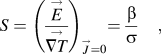 $$S = \left( {{{\mathop E\limits^ \to } \over {\mathop {\nabla T}\limits^ \to }}} \right)_{\mathop J\limits^ \to = 0} = {{\rm{\beta }} \over {\rm{\sigma }}}\quad,$$
or for its absolute value
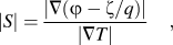 $$|S| = {{|\nabla (\varphi - {\rm{\zeta }}/q)|} \over {|\nabla T|}}\quad,$$
where ζ and ϕ are chemical and electrostatic potentials, respectively, and q is the carrier charge.
The classical theory of thermoelectric phenomena in bulk semiconductors is well developed and standard expressions for all kinetic coefficients (including electrical conductivity σ and thermoelectric coefficient β) based on the solution of the Boltzmann transport equation (BTE) under relaxation time approximation are given in the literature (see, e.g.,Reference Ziman21–Reference Yu and Cardona26). Let us here briefly introduce several necessary results on the Seebeck coefficient S 0 in semiconductors with zero porosity.
The magnitude of S 0 is determined by the band structure and various scattering mechanisms. Furthermore, for definiteness and simplicity, we will restrict ourselves to the consideration of n-type isotropic thermoelectric material with a single parabolic conduction band. According to the kinetic theory, for the material with linear response in the applied electric field and temperature gradient, S 0 can be expressed in the form
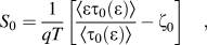 $$S_0 = {1 \over {qT}}\left[ {{{\left\langle {{\rm{\varepsilon \tau }}_0 ({\rm{\varepsilon }})} \right\rangle } \over {\left\langle {{\rm{\tau }}_0 ({\rm{\varepsilon }})} \right\rangle }} - {\rm{\zeta }}_0 } \right]\quad,$$
where  ${\rm{\varepsilon }} = \hbar ^2 k^2 /2m^* ,</tex-math></alternatives> <alternatives><graphic xlink:href="S0884291413001180_inline2" mime-subtype="gif"/><tex-math>\mathop k\limits^ \to$ is the electronic wave vector and
 $m^*$ the effective mass,
 ${\rm{\tau }}_0 ({\rm{\varepsilon }},T)$ is the momentum relaxation time, the bracket denotes the statistical average:
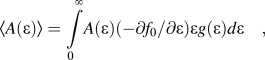 $$\left\langle {A({\rm{\varepsilon }})} \right\rangle = \int\limits_0^\infty \!{A({\rm{\varepsilon }})( - \partial f_0 /\partial {\rm{\varepsilon }}){\rm{\varepsilon }}g({\rm{\varepsilon }})d{\rm{\varepsilon }}} \quad,$$
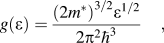 $$g({\rm{\varepsilon }}) = {{(2m^* )^{3/2} {\rm{\varepsilon }}^{1/2} } \over {2{\rm{\pi }}^2 \hbar ^3 }}\quad,$$
is the electronic density of states,  $f_0 ({\rm{\varepsilon }},T) = \left( {\exp \left[ {({\rm{\varepsilon }} - {\rm{\zeta }}_0 )/k_{\rm{B}} T} \right] + 1} \right)^{ - 1}$ is the equilibrium distribution function and ζ0 is the chemical potential. The main scattering mechanisms that limit conductivity in bulk semiconductors are due to phonons and ionized impurities.Reference Kittel23 In the context of this paper, we do not aim to analyze the expressions for the relaxation times τi(ε) due to various scattering mechanisms in the bulk material; rather, we refer the reader to the well-known books.Reference Ziman21–Reference Yu and Cardona26 Note that total bulk relaxation time τ0 in Eq. (3a) determines the carrier mean free path (MFP),
 $\Lambda _0$ given as the average velocity v, divided by the carrier scattering rate
 ${\rm{\tau }}_0^{ - 1} = \mathop\sum\limits_i {{\rm{\tau }}_i^{ - 1} .}$ In crystalline materials,
 $\Lambda _0$ depends on many factors such as temperature, thickness of the sample, doping level etc. The chemical potential is determined by the density of the free charge carriers
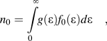 $$n_0 = \int\limits_0^\infty \!\!{g({\rm{\varepsilon }})f_0 ({\rm{\varepsilon }})d{\rm{\varepsilon }}} \quad,$$
and in nondegenerate semiconductors is given byReference Ansel'm22
 $${\rm{\zeta }}_0^* = - \ln (N_{\rm{c}} /n_0 )\quad,$$
where  ${\rm{\zeta }}_0^* = {\rm{\zeta }}_0 /k_{\rm{B}} T$ is the reduced chemical potential relative to the conduction band edge and
 $$N_{\rm c} = 2(2{\rm{\pi }}m^* k_{\rm{B}} T)^{3/2} /h^3 \quad,$$
is the effective density of states. The Seebeck coefficient can be expressed as
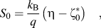 $$S_0 = {{k_{\rm{B}} } \over q}\left( {{\rm{\eta }} - {\rm{\zeta }}_0^* } \right)\quad,$$
where the parameter η depends on the scattering mechanism; e.g., η = 2 for carrier scattering on acoustic phonons and η = 4 for scattering on ionized impurities. Note that according to Eqs. (6a) and (7), when the free carrier density decreases, the Seebeck coefficient increases in absolute values.
Later in the paper we will use these results to calculate the Seebeck coefficient in porous materials. The paper is organized as follows: in the next section the details of modeling for the porous material with inhomogeneous porosity are given and the Seebeck coefficient for a layer with periodically distributed identical pores is considered. In Sec. III, we derive an analytical expression for the effective Seebeck coefficient S of the porous composite with graded inhomogeneous porosity. In Sec. IV, we consider several particular cases of the pore distribution in different layers including a specific isoentropic case. Finally, in Sec. V we make concluded remarks.
II. MODELING. THERMOPOWER OF A LAYER WITH IDENTICAL PORES
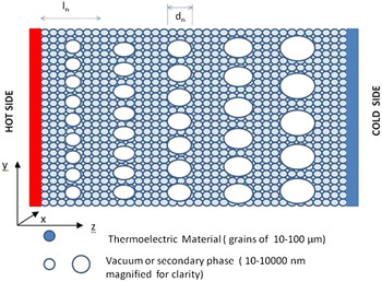
Following,Reference Tarkhanyan and Niarchos20 we model a porous material as a composite consisting of N alternating layers of various thicknesses l n, n = 1, 2,…N. There are periodically distributed identical spherical hole pores of d n diameter in each layer. The latter is assumed to be various in distinct layers, while the pore lattice period a n and the layers’ thickness may be the same. Such a material behaves like a multilayer system consisting of layers of identical host materials with inhomogeneous porosity (Fig. 1). Note that the lattice period can be expressed as a n = d n + δn, where δn is the distance between the adjacent pores.
Schematic illustration of the multilayer configuration with layers of different porosity (graded porous material). Each layer contains a concentration of periodically distributed pores of the same size (only one row of such particles is shown).

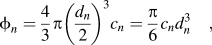
Let us choose a Cartesian coordinate system with z-axis perpendicular to the plane of the layers, so that the first layer with n = 1 occupies the space region 0 ≤ z ≤ l 1, 0 ≤ x, y ≤ L x, y, where L x, y are the lengths of the sample in the x, y directions, and the nth layer occupies the region l n−1 ≤ z ≤ l n. By definition, the volume fraction (porosity) of the nth layer is
 $$\phi _n = {4 \over 3}{\rm{\pi }}\left( {{{d_n } \over 2}} \right)^3 c_n = {{\rm{\pi }} \over 6}c_n d_n^3 \quad,$$
where  $c_n = a_n^{ - 3}$ is the concentration of the pores. Since d n < a n, it is evident that the porosity is limited from the above:
 $\phi _n \lt {\rm{\pi }}/6$. Setting, e.g., d n ≤ δn, we obtain
 $\phi _n \le {\rm{\pi }}/48,$ that is, the volume fraction is assumed to be small.
Net porosity of the composite (ratio of the pore volume to the total volume of the composite) is given by
 $$\phi = {1 \over {L_z }}\mathop\sum\limits_{n = 1}^N {l_n \phi _n } = {{\rm{\pi }} \over {6L_z }}\mathop\sum\limits_{n - 1}^N {l_n c_n d_n ^3 } \quad,$$
where L z is the composite thickness in the z-direction.
Consider the composite in the presence of temperature gradient from T h at the plane z = 0 to T c at 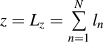 $z = L_z = \mathop\sum\limits_{n = 1}^N {l_n }$, and the temperature is taken to be uniform in the xy-plane. The Seebeck coefficient of a single layer containing pores of equal sizes d n can be given by Eqs. (3a) and (3b), where sub-index 0 should be replaced by n, so as τn(ε) ≡ τn is the combined relaxation time and
 ${\rm{\zeta }}_n$ is the chemical potential in the layer. Clearly, the presence of the pores drastically changes the electronic properties of the material compared with those in the bulk material. In this paper, we will neglect possible changes in the carrier effective mass due to the band-bend at pore-medium interfaces and assume that there are no charge carriers inside the pores. In porous semiconductor materials, free charge carriers are absent not only inside the pores, but also in small spherical regions around the pores due to the presence of deep surface states which act as electron traps. These trap centers are situated at pore/medium interfaces with areal density N s and are characterized by localized energy E T near or above the middle of the band gap. Total number of traps per pore is then
 ${\rm{\pi }}d_n^2 N_s$ while the volume density is given by
 $$N_T = {\rm{\pi }}d_n^2 N_s c_n = 6\phi _n N_s /d_n \quad,$$
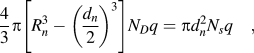
where c n is eliminated with use of Eq. (8). Usually, N T << N D, where N D is the net density of shallow donors with energy of ionization εD. In temperature range εD < kBT < εG, where εG is the width of the band gap, all the donors are assumed to be ionized, and then the density of electrons in the bulk material is  $n_0 \cong N_D .$ As electrons are trapped, spherical regions depleted of free electrons form around the pores. Assuming that all trap states are filled by frozen-in electrons and that there is no thermal emission from these states, the condition of electrical neutrality can be written as
 $${4 \over 3}{\rm{\pi }}\left[ {R_n^3 - \left( {{{d_n } \over 2}} \right)^3 } \right]N_D q = {\rm{\pi }}d_n^2 N_s q\quad,$$
where R n is the radius of the depleted region. Obviously, trapping results in change of free carriers’ concentration. Using Eq. (11) one obtains
 $$R_n = {{d_n } \over 2}\left( {1 + {{N_T } \over {\phi _n N_D }}} \right)^{1/3} \approx {{d_n } \over 2} + {{N_s } \over {N_D }}\quad.$$
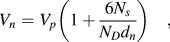
Thus, the thickness of the carrier depletion region is equal to N s/N D while the volume per pore with no mobile electron is given by
 $$V_n = V_p \left( {1 + {{6N_s } \over {N_D d_n }}} \right)\quad,$$
where  $V_p = {\rm{\pi }}d_n^3 /6$ is the pore volume. It means that the “effective porosity” with respect to mobile electrons is equal to
 $$\phi _n^{{\rm{eff}}} = V_n c_n = V_n \phi _n /V_p = \phi _n (1 + 6N_s /d_n N_D )\quad.$$
Treating now the porous layer as an effective medium with average concentration of free electrons
 $$n_n = n_0 (1 - \phi _n^{{\rm{eff}}} )\quad.$$
One can calculate the Fermi energy in the material. Furthermore, we will restrict ourselves to the consideration of nondegenerate semiconductors. Then, assuming  $\exp ( - {\rm{\zeta }}_0^* ) > > 1$, for the reduced chemical potential we obtain
 $${\rm{\zeta }}_n^* = - \ln (N_c /n_n ) = {\rm{\zeta }}_0^* + \ln (1 - \phi _n^{{\rm{eff}}} )\quad,$$
where  ${\rm{\zeta }}_0^*$ is given by Eq. (6a). From Eq. (14c) one can conclude that the presence of porosity leads to increasing in the absolute value of the chemical potential.
Neglecting for simplicity the possible anisotropy of scattering at the pore/medium interfaces and using Matthiessen’s rule for scattering events which are independent from each other, the combined relaxation time τn can be given byReference Ziman21–Reference Touloukian, Powell, Ho and Klemens27
 $${\rm{\tau }}_n^{ - 1} = {\rm{\tau }}_0^{ - 1} + {\rm{\tau }}_{pn}^{ - 1} \quad,$$
where τpn is the electronic momentum relaxation time due to the scattering at pore/medium interfaces in the nth layer. It is not difficult to see that
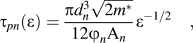 $${\rm{\tau }}_{pn} ({\rm{\varepsilon }}) = {{{\rm{\pi }}d_n^3 \sqrt {2m^* } } \over {12\varphi _n {\rm A}_n }}{\rm{\varepsilon }}^{ - 1/2} \quad,$$
where A n is the effective cross-section area. Indeed, when a charge carrier travels a distance L, the average number of its collisions with pores is equal to  ${\rm{\gamma }} = A_n Lc_n$. Then, carrier MFP can be estimated as
 $$\Lambda _{pn} = L/{\rm{\gamma }} = (A_n c_n )^{ - 1} \quad.$$
Therefore, the inverse relaxation time is equal to
 $${\rm{\tau }}_{pn}^{ - 1} = v/\Lambda _{pn} = vA_n c_n \quad,$$
where v(ε) = (2ε/m*)1/2 is the electronic velocity. Substituting here c n from Eq. (8), for τpn we obtain Eq. (16). Note that in classical mechanics  $A_n = {\rm{\pi }}R_n^2 ,$ and then Eq. (16) gives
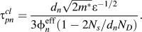 $${\rm{\tau }}_{pn}^{cl} = {{d_n \sqrt {2m^* } {\rm{\varepsilon }}^{ - 1/2} } \over {3\phi _n^{{\rm{eff}}} (1 - 2N_s /d_n N_D )}}\quad.$$
To find the quantum mechanical expression for the scattering cross-section, let us consider pores as energy barriers with spherical scattering potential U n(r)=U 0n at r < R n and U n(r) = 0 at r > R n, where r is the distance from the center of the pore. Assuming that the low energy electrons scatter strongly (i.e., the transmission probability is negligible) while the high-energy ones are practically unaffected, the following expression for slow carriers with energy ε << U 0n can be found from Fermi’s golden ruleReference Landau and Lifshitz28:
 $$A_n = 4{\rm{\pi }}B_n^2 \quad,$$
where
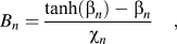 $$B_n = {{\tanh ({\rm{\beta }}_n ) - {\rm{\beta }}_n } \over {{\rm{\chi }}_n }}\quad,$$
is the scattering amplitude given by the wave function
 $${\rm{\psi }}_n \{ r\} = \{ 1 + B_n /r\} \exp \{ i\mathop k\limits^ \to \mathop r\limits^ \to \} \quad,$$
which is a solution of the Schrödinger equation
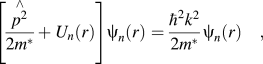 $$\left[ {{{\mathop {p^2 }\limits^ \wedge } \over {2m^* }} + U_n (r)} \right]{\rm{\psi }}_n (r) = {{\hbar ^2 k^2 } \over {2m^* }}{\rm{\psi }}_n (r)\quad,$$
and
 $${\rm{\beta }}_n \,\equiv\, {\rm{\chi }}_n R_n ,{\rm{\chi }}_n \,\equiv \,\sqrt {2m^* U_{0n} } /\hbar \quad.$$
Within the Born approximation βn << 1, that is, when
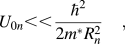 $$U_{0n} \lt \lt {{\hbar ^2 } \over {2m^* R_n^2 }}\quad,$$
Eqs. (19a), (19b), and (16) give
 $$A_n = 4{\rm{\pi }}R_n^2 {\rm{\beta }}_n^4 /9\quad,$$
 $${\rm{\tau }}_{pn} = {9 \over {4{\rm{\beta }}_n^4 }}{\rm{\tau }}_{pn}^{cl} = {{3\hbar ^4 {\rm{\varepsilon }}^{ - 1/2} } \over {2R^3 (2m^* )^{3/2} U_{0n}^2 \phi _n^{{\rm{eff}}} }}\quad.$$
In the opposite limiting case βn >> 1 we obtain
 $$A_n = 4{\rm{\pi }}R_n^2 \quad,$$
and
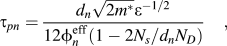 $${\rm{\tau }}_{pn} = {{d_n \sqrt {2m^* } {\rm{\varepsilon }}^{ - 1/2} } \over {12\phi _n^{{\rm{eff}}} (1 - 2N_s /d_n N_D )}}\quad,$$
which is 4 times smaller than in the classical case.
Thus, according to Eqs. (15) and (18–24b), the combined carrier relaxation time in a homogeneously porous layer can be expressed as
 $${\rm{\tau }}_n = {{{\rm{\tau }}_0 } \over {1 + {\rm{\gamma }}_n \phi _n^{{\rm{eff}}} {\rm{\tau }}_0 \sqrt {{\rm{\varepsilon }}/2m^* } }}\quad,$$
where
 $${\rm{\gamma }}_n = \left\{ {\matrix{ {{\rm{3}}d_n^{ - 1} {\rm{(1}} - {\rm{2}}N_s {\rm{/}}d_n N_D {\rm{)\!\!: \,classical \,\,case;}}} \cr {{{2R_n^3 (2m^* U_{0n} )^2 } \over {3\hbar ^4 }}{\rm{: quantum\, \,mechanical \,\,case \,\,at \,\,\beta }}_n \,{\rm{ \lt \lt 1; }}} \cr {{\rm{12}}d_n^{ - 1} {\rm{(1 - 2}}N_s {\rm{/}}d_n N_D {\rm{)\!\!: quantum\,\, mechanical \,\,case\,\, at \,\,\beta }}_n \,> > 1\quad.} \cr } } \right.$$
For definiteness, we will further consider the case of relatively low impurity concentrations, so that the main contribution in the carrier relaxation time at zero porosity is from the scattering on deformation potential of acoustic phonons. Then, settingReference Ansel'm22,Reference Touloukian, Powell, Ho and Klemens27
 $${\rm{\tau }}_0 = a{\rm{\varepsilon }}^{ - 1/2} \quad,$$
where
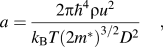 $$a = {{2{\rm{\pi }}\hbar ^4 {\rm{\rho }}u^2 } \over {k_{\rm{B}} T(2m^* )^{3/2} D^2 }}\quad,$$
is the constant for the acoustic phonons, ρ–the mass density, u–the longitudinal velocity of the sound and D is the deformation potential constant, from Eq. (25) we obtain
 $${\rm{\tau }}_n = {{a{\rm{\varepsilon }}^{ - 1/2} } \over {1 + a{\rm{\gamma }}_n \phi _n^{{\rm{eff}}} (2m^* )^{ - 1/2} }}\quad.$$
Substitution of Eq. (28) into the expression for S n with the use of Eq. (7) at η = 2 (carrier scattering on acoustic phonons) gives
 $${{S_n } \over {S_0 }} = {1 \over {(2 - {\rm{\zeta }}_0^* )k_{\rm{B}} T}}\left( {{{I_2 } \over {I_1 }} - {\rm{\zeta }}_n } \right)\quad,$$
where
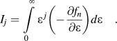 $$I_j = \int\limits_0^\infty {\varepsilon ^{\,j} \left( { - {{\partial f_n } \over {\partial {\rm{\varepsilon }}}}} \right)} d{\rm{\varepsilon }}\quad.$$
Taking into account that for the Boltzmann distribution of free electrons  $( - \partial f_n /\partial {\rm{\varepsilon ) = (}}k_{\rm{B}} T)^{ - 1} \exp [({\rm{\zeta }}_n - {\rm{\varepsilon )/}}k_{\rm{B}} T]$ and denoting ε/
 $k_{\rm{B}} T$ = x 2, we obtain
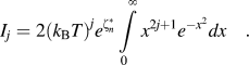 $$I_j = 2(k_{\rm{B}} T)^j e^{{\rm{\zeta }}_n^* } \int\limits_0^\infty {x^{2j + 1} e^{ - x^2 } } dx\quad.$$
Then Eq. (29a) gives
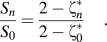 $${{S_n } \over {S_0 }} = {{2 - {\rm{\zeta }}_n^* } \over {2 - {\rm{\zeta }}_0^* }}\quad.$$
Using now Eq. (14c), one can find that
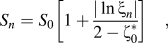 $$S_n = S_0 \left[ {1 + {{|\ln {\rm{\xi }}_n |} \over {2 - {\rm{\zeta }}_0^* }}} \right]\quad,$$
where
 $${\rm{\xi }}_n \,\equiv\, 1 - \phi _n^{{\rm{eff}}} \quad.$$
Since ζ0 < 0, from Eq. (30a) it is evident that the Seebeck coefficient of a single porous layer is greater than S 0. Thus, the presence of porosity always leads to the enhancement in the absolute value of the Seebeck coefficient. At this end, the relative growth is given by
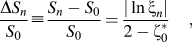 $${{\Delta S_n } \over {S_0 }} \equiv {{S_n - S_0 } \over {S_0 }} = {{|\ln {\rm{\xi }}_n |} \over {2 - {\rm{\zeta }}_0^* }}\quad,$$
according to which it increases monotonically by logarithmic law with increasing of the effective porosity.
III. EFFECTIVE THERMOPOWER OF THE COMPOSITE WITH INHOMOGENEOUS POROSITY
As it is well known (see, e.g.,Reference Callen29), the thermopower is equivalent to entropy per carrier per charge, i.e., the effective Seebeck coefficient for the total composite and for a single layer of the composite can be expressed as
 $$S = E_t /qN_t \quad,$$
and
 $$S_n = E_n /qN_n \quad,$$
respectively, where E t and N t are the total entropy of the composite and total number of the carriers, while E n and N n denote the entropy and carrier number for the nth layer. On the other hand, it is well known that total entropy of a system in local equilibrium conditions is an additive quantityReference de Groot and Mazur30:
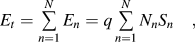 $$E_t = \mathop\sum\limits_{n = 1}^N {E_n } = q\mathop\sum\limits_{n = 1}^N {N_n } S_n \quad,$$
where
 $$N_n = L_x L_y l_n n_n \quad,$$
and therefore
 $$N_t = \mathop\sum\limits_{n = 1}^N {N_n } = L_x L_y \mathop\sum\limits_{n = 1}^N {l_n } n_n \quad.$$
Using Eqs. (31a)–(33b) and assuming for simplicity that l n = const, we obtain
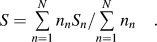 $$S = \mathop\sum\limits_{n = 1}^N {n_n S_n } /\!\mathop\sum\limits_{n = 1}^N {n_n } \quad.$$
A substitution of Eqs. (14b) and (30a) into (34) gives
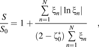 $${S \over {S_0 }} = 1 + {{\mathop\sum\limits_{n = 1}^N {{\rm{\xi }}_n } |\ln {\rm{\xi }}_n |} \over {(2 - {\rm{\zeta }}_0^* )\mathop\sum\limits_{n = 1}^N {{\rm{\xi }}_n } }}\quad,$$
Equation (35) for the ratio of the effective Seebeck coefficient of the composite with inhomogeneous porosity to its value in case of zero porosity is sufficiently general and sound for application in a specific experimental situation. Obviously, for a material with homogeneous porosity it coincides with Eq. (30a). We also note that the sum in the denominator of Eq. (35) can be expressed as
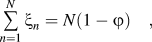 $$\mathop\sum\limits_{n = 1}^N {{\rm{\xi }}_n } = N(1 - \varphi )\quad,$$
where
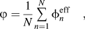 $$\varphi = {1 \over N}\mathop\sum\limits_{n = 1}^N {\phi _n^{{\rm{eff}}} } \quad,$$
is the average “effective porosity” of the composite. Then for the relative growth of the effective Seebeck coefficient from Eq. (35) we obtain
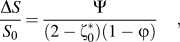 $${{\Delta S} \over {S_0 }} = {\Psi \over {(2 - {\rm{\zeta }}_0^* )(1 - \varphi )}}\quad,$$
where
 $$\Psi = {1 \over N}\mathop\sum\limits_{n = 1}^N {{\rm{\xi }}_n |\ln ({\rm{\xi }}_n )| = } {1 \over N}\left| {\ln \left( {\prod\limits_{n = 1}^N {{\rm{\xi }}_n^{{\rm{\xi }}_n } } } \right)} \right|\quad.$$
As it can be seen from Eqs. (38) and (39), the enhancement in the absolute value of S increases with increasing of the average porosity ϕ and does not depend on the orientation of the porosity gradient with respect to the direction of the temperature gradient.
IV. SEVERAL PARTICULAR CASES
To simplify Eqs. (38) and (39), let us consider the case when the pore concentration in each layer of the composite is the same: a n = const ≡ a 0. Assuming, for example, that the pore diameter in the nth layer is given by the law.
 $$d_n = nd_{\min } \quad,$$
where d min is the diameter of the smallest pores periodically distributed in the first layer at the hot side of the composite and using Eqs. (14a), (10), and (8), the “effective porosity” in Eq. (30b) can be written in the form
 $$\phi _n^{{\rm{eff}}} = {\rm{\alpha }}_1 \left( {{\rm{\alpha }}_2 n^2 + n^3 /6} \right)\quad,$$
where
 $${\rm{\alpha }}_1 \,\equiv \,{\rm{\pi }}\left( {d_{\min } /a_0 } \right)^3 ,\,{\rm{\alpha }}_2 \,\equiv \,N_s /d_{\min } N_d \quad.$$
Then, as it can be seen from Eqs. (37) and (41), the average “effective porosity” of the composite is given by
 $$\varphi = {\rm{\alpha }}_1 (N + 1)[{\rm{\alpha }}_2 (2N + 1) + N(N + 1)/4]/6\quad,$$
and quickly increases with increasing of the total number of the layers N. The enhancement in φ leads to the increasing of the Seebeck coefficient. On the other hand, since the diameter of the biggest pores d N = N maxd min is limited by the condition d N < a 0, it is evident that
 $$N_{\max } \,\lt \,a_0 /d_{\min }\quad .$$
Setting, e.g., a 0 = 120 nm, d min = 20 nm, N s = 1010 cm−2 and N D = 1016 cm−3, we obtain N max = 5, α1 = 6−3π, α2 = 0.5. Then Eqs. (43), (38), and (39) at N = N max give φ = 0.189, Ψ = 0.15 and
 $$\Delta S/S_0 = 0.185/(2 - {\rm{\zeta }}_0^* )\quad,$$
which for  ${\rm{\zeta }}_0^* = - 3$ (i.e., at S 0 =431.25 μV/K) results in only ∼3.7% enhancement of the Seebeck coefficient compared to that in the bulk material.
Let us consider now the opposite case of the pore arrangement, when the biggest pores are distributed in the first layer at the hot side of the composite, and the pore diameters in the next layers are given by the law.
 $$d_n = d_{\max } (N + 1 - n)/N\quad,$$
i.e., d n depends also on the total number of the layers N.
Note that at N = 5 and d max = 100 nm this composite differs from the previous one only by opposite arrangement of the layers with respect to the direction of the temperature gradient. For any other value of N, the composites are quite different from each other. At a given value of N, the effective porosity of the nth layer is equal to
 $$\phi _n^{{\rm{eff}}} = {\rm{\alpha }}_3 (N + 1 - n)^2 [{\rm{\alpha }}_4 + (N + 1 - n)/6N]/N^2 \quad,$$
where
 $${\rm{\alpha }}_3 = {\rm{\pi }}(d_{\max } /a_0 )^3 ,\,{\rm{\alpha }}_4 \,\equiv\, N_s /d_{\max } N_d \quad.$$
Using Eqs. (37) and (46b), for the average effective porosity we obtain
 $$\!\varphi = {\rm{\alpha }}_3 (N + 1)[(N + 1)/4 + {\rm{\alpha }}_4 (2N + 1)]/6N^2 \quad,$$
according to which ϕ decreases monotonically with increasing of N. It means that, unlike to the previous case, the Seebeck coefficient of the composite decreases with increase of the number of the layers with different porosity.
Note that at N = 5 and d max = 100 nm Eqs. (43) and (47) give the same value for the φ, i.e., there is no discrepancy between the two opposite directions for the arrangement of the layers with distinct pore sizes. Note also that in the case under consideration, unlike the previous one, there is no limitation for the N. Putting, for example, N = 10, d max = 100 nm and the same values for N s and N d as in the previous case, we obtain α3 = 1.817, α4 = 0.1, and then Eqs. (38), (39), and (47) give Ψ = 0.132, ϕ = 0.162 and
 $$\Delta S/S_0 = 0.158(2 - {\rm{\zeta }}_0^* )^{ - 1} \quad.$$
At the same  ${\rm{\zeta }}_0^* = - 3$Eq. (48) results in ∼3% enhancement in S compared to that in the bulk material.
Finally, we will consider a composite in which the following condition for the diameter of the smallest pores is fulfilled:
 $$d_{\min } > > 6N_s /N_D \quad.$$
In this case, as it follows from Eq. (14a), one can neglect trapping effects. For N s = 1010 cm−2 and N d = 1016 cm−3, condition (49) gives d min >> 60 nm. In the following, this condition is assumed to be satisfied.
Let’s consider briefly the case when the pore diameters in different layers of the composite are changing according to the law.
 $$d_n = d_{\min } n^{1/3} \quad.$$
Then ξn = 1 − α1n/6 and the average porosity in Eq. (38) is equal to φ = α1(N + 1)/12, where α1 is given by Eq. (42). It is not difficult to see that in the range
 $$6N_s /N_D \,\lt \lt \,d_{\min }\, \lt \lt \,a_0(6/{\rm{\pi }}N)^{1/3} \quad,$$
the parameter α1n/6 << 1. Replacing then ln(ξn) in Eq. (39) by the series
 $$\!\!\!\!\ln \left( {1 - {{{\rm{\alpha }}_1 n} \over 6}} \right) = - {{{\rm{\alpha }}_1 n} \over 6}\left[ {1 + {{{\rm{\alpha }}_1 n} \over {12}} + {{({\rm{\alpha }}_1 n)^2 } \over {108}} + ...} \right],$$
after summation over n we obtain
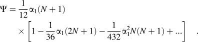 $$\eqalign{\Psi = \,{1 \over {12}}{\rm{\alpha }}_1 (N + 1)\cr\times \left[ {1 - {1 \over {36}}{\rm{\alpha }}_1 (2N + 1) - {1 \over {432}}{\rm{\alpha }}_1^2 N(N + 1) + ...} \right].$$
Setting, for example, N = 8, d min = 1 μm, a 0 = 5 μm, we obtain α1 = 5−3π, Ψ = 0.0745 and the average porosity φ = 1.9%. Then from Eq. (38) for the relative growth of the Seebeck coefficient at the same value of reduced chemical potential as in the previous cases we obtain ΔS/S 0 = 1.5%.
Let us consider also a special case of the composite with homogeneous porosity when both the pore concentrations and pore sizes in different layers are changing in such a way that the porosity of all the layers remains the same:  $\phi _n = {\rm{const}} \,\equiv\, \phi$. Such a behavior of the structure is possible only if the following condition for the ratio of the pore lattice period and pore diameter is fulfilled for all layers of the composite: d n/a n = const = α. Then Eq. (35) should be replaced by
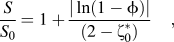 $${S \over {S_0 }} = 1 + {{|\ln (1 - \phi )|} \over {(2 - {\rm{\zeta }}_0^* )}}\quad,$$
where ϕ = πα3/6. Setting, e.g., α = 0.5, for the relative growth of the Seebeck coefficient we obtain ΔS/S 0 ∼ 1.3%. It also should be noted that in this case all the layers of the structure are characterized by the same entropy. Then, from Eq. (32) for the total entropy of the composite we obtain
 $$\!E_t = qN_t S = qn_0 (1 - \phi )V\left[ {S_0 - {{k_{\rm{B}} } \over q}\ln (1 - \phi )} \right]\quad,$$
where V is the total volume of the composite. We also note that the enhancement in the Seebeck coefficient of such an “isoentropic” porous composite is independent from both the number of the layers with different pore sizes and the order of the arrangement of big and small pores.
V. CONCLUSIONS
By modeling a porous composite material with inhomogeneous porosity as a combination of the layers of different porosity, we have derived a simple expression for the Seebeck coefficient as a function of porosity, pore sizes and the number of the pore groups N with different characteristic sizes. We have shown that porosity always leads to the enhancement in the absolute value of the Seebeck coefficient. Physical mechanism of the enhancement is an increasing of the entropy of a porous composite. In the case when the main contribution in the carrier relaxation time at zero porosity is from the scattering on deformation potential of acoustic phonons, the enhancement of entropy is caused by shifting of the Fermi level in the band-gap to the direction away from the bottom of the conduction band due to decreasing of the averaged number density of electrons in a porous material as compared to its value in the bulk material of the same volume.
We have shown that in the composite with inhomogeneous porosity there is no asymmetry between the two opposite directions of arrangement for big and small pores with respect to the direction of the temperature gradient. We have as well shown that the presence of various pore groups with different diameters of spherical hole pores does not lead to significant enhancement in the absolute value of the Seebeck coefficient compared to bulk materials with zero porosity and to porous materials with homogeneous porosity.
Thus, the main physical mechanism for an enhancement in thermoelectric figure-of-merit of a porous material is the reduction of the thermal conductivity due to effective phonon scattering on the pore boundaries at the presence of the size effect.
ACKNOWLEDGMENT
This work is supported by project NEXTEC of EU.