





Introduction
Surface-guided radiotherapy (SGRT) is used alongside Volumetric Modulated Arc Therapy (VMAT) for Deep Inspiration Breath Hold (DIBH) breast patients to reduce cardiotoxicity, Reference Jensen, Roa, Johansen, Lund and Frengen1–Reference Huijskens, Granton and Fremeijer3 particularly if the Internal Mammary Node (IMN) is treated Reference Osman, Hol, Poortmans and Essers4 and is recommended in both National Institute for Health and Care Excellence (NICE) 5 and Royal College of Radiologists (RCR) guidelines. 6 SGRT systems, such as VisionRT’s AlignRT, use three optical surface cameras to project a pseudorandom speckled pattern onto the patient. This is then reconstructed via triangulation to allow submillimetre monitoring in real time. Reference Freislederer, Batista and Öllers7–Reference Bellala, Kuppusamy and Bellala10 One camera is positioned at the end of the treatment couch with two cameras positioned laterally. Continuous monitoring is advantageous as it increases safety alongside accuracy of treatment Reference Kügele, Mannerberg and Nørring Bekke11 as the system is interfaced with the linac to allow for beam gating outside set tolerances. These tolerances are defined using real-time deltas (RTDs), which represent any displacement between the patient’s current position compared to the Computed Tomography-Digital Imaging and Communications in Medicine (CT-DICOM)-generated reference surface to six degrees of freedom. 12
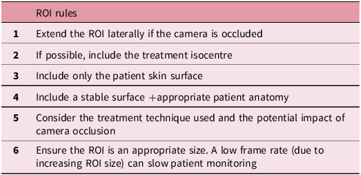
The system utilises a user-defined region of interest (ROI) for accurate registration and monitoring. The ROI should include stable anatomy, such as the sternum, ribs and breast tissue, and include the isocentre where possible. VisionRT has produced different ROI templates and has written a set of rules to follow for ROI delineation 13 (Table 1). European Society for Radiotherapy and Oncology – Advisory Committee for Radiation Oncology Practice (ESTRO-ACROP) Reference Freislederer, Batista and Öllers7 and American Association for Physicists in Medicine (AAPM) Reference Al-Hallaq, Cerviño and Gutierrez8 SGRT guidelines highlight the importance of using an appropriate ROI which includes distinct anatomical regions to ensure accurate treatment and monitoring with SGRT. A publication from Sauer et al. Reference Sauer, Ott, Lahmer, Fietkau and Bert14 also highlights the importance of an ROI including the breast, sternum and a band under the contralateral breast. However, other suggestions for ROIs have been made, including a band across both breasts Reference Li, Lu and O’Grady15 or excluding breast tissue Reference Bellala, Kuppusamy and Bellala10 for rotational treatment techniques to ensure accurate monitoring as the gantry rotates.
ROI rules suggested by VisionRT13 to ensure the most appropriate ROI

Table 1. Long description
A table listing rules for defining a region of interest (ROI) in medical imaging. The table has six rows and one column. Row 1: Extend the ROI laterally if the camera is occluded. Row 2: If possible, include the treatment isocentre. Row 3: Include only the patient skin surface. Row 4: Include a stable surface and appropriate patient anatomy. Row 5: Consider the treatment technique used and the potential impact of camera occlusion. Row 6: Ensure the ROI is an appropriate size. A low frame rate due to increasing ROI size can slow patient monitoring.
In clinical practice, SGRT has now been incorporated into workflows to aid set up and DIBH Reference Freislederer, Batista and Öllers7,Reference Batista, Meyer, Kügele and Al-Hallaq16 typically alongside gold-standard image-guided radiotherapy. However, it can be limited by cost and training implementations Reference Batista, Meyer, Kügele and Al-Hallaq16 and line-of-sight issues causing camera occlusion by the gantry, imaging panels or the patient. Reference Freislederer, Batista and Öllers7,Reference Al-Hallaq, Cerviño and Gutierrez8
Camera occlusion can result in interruptions in surface monitoring when either one or both lateral cameras are occluded by the gantry and/or the imaging equipment rotating. Reference Al-Hallaq, Cerviño and Gutierrez8 This can increase uncertainty of the patient’s position and reduce software precision Reference Freislederer, Batista and Öllers7,Reference Al-Hallaq, Cerviño and Gutierrez8,Reference Stevens, Moloney and Blackmore17 which is particularly important when patients are in unstable DIBH positions. This can impact clinical workflow as patients may breathe out or move when cameras are occluded which may not be recognised until monitoring resumes. Additionally, if a patient breathes out during camera occlusion, it can be difficult to re-enter an accurate DIBH without the SGRT system recognising a patient’s position. Both these scenarios can lead to delays in treatment completion.
Both ESTRO-ACROP Reference Freislederer, Batista and Öllers7 and AAPM Reference Al-Hallaq, Cerviño and Gutierrez8 SGRT guidelines recognise the issue of camera occlusion and recommend modifying the ROI to improve tracking accuracy; larger ROIs that cross the midline may reduce the impact of camera occlusion. Additionally, some SGRT studies have highlighted the impact of camera occlusion, with suggestions of creating a larger ROI to reduce gantry blocking during VMAT Reference Li, Lu and O’Grady15 and extending ROIs laterally if cameras are blocked, Reference Bellala, Kuppusamy and Bellala10 which is further supported in VisionRT ROI rules 13 (Table 1).
Despite this, there is a lack of literature aimed particularly at assessing the impact of camera occlusion in rotational imaging/treatment and which ROI is most appropriate for these patients. However, this has been reported anecdotally in SGRT forums, 18 with users describing ‘gantry blocking’ and suggesting troubleshooting methods, highlighting the wider impact on clinical workflows.
Hence, this project had two main aims:
-
• To quantify the duration and gantry angles of interruptions of the RTDs due to camera occlusion by either the gantry or imaging equipment.
-
• To determine if the ROIs can be optimised for DIBH VMAT Cone Beam Computed Tomography (CBCT) breast patients to mitigate the impact of interruptions caused by camera occlusion and incorporate this into clinical workflows.
Methods
Ethical approval was not required for this evaluation as no patient data were used. Project approval was granted by the Quality Improvement and Clinical Audit team at the trust.
Anthropomorphic phantom
An anthropomorphic phantom was used based on literature suggestions for testing ROIs and gantry angles at QA and commissioning using phantoms. Reference Freislederer, Batista and Öllers7,Reference Al-Hallaq, Cerviño and Gutierrez8,Reference Biltekin and Özyiğit19 The phantom was made from heavy-duty plastic which was matte and light-coloured to ensure no reflection from the SGRT cameras and represented a body habitus from neck to upper thigh. Exact measurements are displayed in Figure 1a. A 9-cm poly cushion was placed at the inferior aspect of the phantom to better represent a patient contour and reference capture taken (Figure 1b). These SGRT reference captures were also used in the project, representing the phantom’s position in real time.
(a) Measurements of the anthropomorphic phantom used and (b) the phantom placed on the breast board with a 9-cm cushion at the inferior aspect.

CT scan and plan
A CT scan was performed using a Philips wide-boar CT scanner. The phantom was placed on a CIVCO C-QualTM supine breast board indexed on a kVueTM Q-Fix couch top at a 10-degree angle to mimic treatment position for VMAT breast patients. The phantom was scanned on a breast protocol with 3 mm slice thickness, and this would replicate the breath-hold position for this project. The scan was then exported to radiotherapy treatment planning, where a mock VMAT treatment plan and DICOM reference surface were generated which allowed the ROIs to be delineated.
ROI selection
Six different ROIs were selected and drawn on a VisionRT offline terminal. These were based on clinical practice and literature suggestions and are presented in Figure 2.
Six different ROIs which were drawn on the anthropomorphic phantom based on literature suggestions and current clinical practice.

Figure 2. Long description
The cross-sectional view shows an anthropomorphic phantom with six different regions of interest (ROIs) highlighted in green. Panel A: ROI_WB (Whole breast) shows a green highlighted area covering the entire breast region. Panel B: ROI_WBT (Whole breast + tail) displays a green highlighted area covering the whole breast and extending into the tail region. Panel C: ROI_WBHC (Whole breast + half contralateral breast) features a green highlighted area covering the whole breast and half of the contralateral breast. Panel D: ROI_WBFC (Whole breast + full contralateral breast) shows a green highlighted area covering the whole breast and the full contralateral breast. Panel E: ROI_T (Inverted T) displays a green highlighted area shaped like an inverted T. Panel F: ROI_CROSS (X-shaped) features a green highlighted area shaped like an X.
Data collection and analysis
Screen recordings and screenshots of the VisionRT system were utilised for retrospective analysis of the tests performed.
For the initial test of camera occlusion, the Elekta Versa HD (Elekta Ltd, Crawley, UK) gantry was rotated from the CBCT start angle to the stop angle with the X-ray Volume Imaging (XVI) panel and source angle extended. This was then replicated for the VMAT arc with the imaging equipment retracted. This was repeated for each ROI and camera occlusion gantry angles recorded.
Postural video test
To determine at which gantry angles there was a greater probability of camera occlusion occurring, the postural camera feature on AlignRT was used to create a pods eye view (PEV). Postural video was selected for each lateral camera pod in turn, while the gantry was rotated for both the CBCT and the treatment arc. The gantry angle at which approximately 50% of the phantom’s surface/camera view was blocked by either the gantry, imaging panel or kV source arm was recorded.
Sensitivity test
A sensitivity test was conducted to determine how sensitive each ROI is to the magnitude of couch movements when tracked by the AlignRT system and how camera occlusion may impact this. An ROI is less sensitive to camera occlusion the greater distance it is tracked by AlignRT before full occlusion occurs (the system displays a loss of tracking/poor correspondence message). Therefore, a greater magnitude of couch movement (cm) corresponds to a less sensitive and more robust ROI.
The sensitivity of ROIs was measured at gantry angles of 0 degrees and 50 for both the CBCT (CBCT0 and CBCT50) and treatment arc (ARC0 and ARC50). The treatment couch was moved in each translational direction to the point in which the AlignRT software was unable to track the ROI resulting in the error message ‘poor correspondence’, and the treatment couch position was recorded.
Approximate percentage surface area test
Screenshots were taken of each ROI during live monitoring of the AlignRT system at five different gantry angles (290, 0, 60, 120 and 180 degrees) for both the CBCT and treatment arc. Sketch and Calc software was used to plot and calculate the approximate percentage surface area in 2D of the ROI which was visible to the AlignRT cameras when occlusion occurred.
Data from each test were collated and analysed in Excel where graphs were generated for evaluation. Statistical analysis was not performed as one dataset was collected from this phantom as this was a preliminary technical evaluation into the camera occlusion with SGRT.
Results
Primary findings
No full camera occlusion was demonstrated during the CBCT or treatment arc when using a phantom.
However, using the postural camera view, the gantry angles with greater probability of camera occlusion were plotted. As displayed in Figure 3a, there is an overlap in lateral camera occlusion between 10 and 60 degrees for the CBCT arc from the gantry head and kV panel.
The areas of camera occlusion for both the CBCT arc (a) and the treatment arc (b) for both the lateral cameras on the AlignRT system.

Sensitivity tests
Figure 4(a–f) demonstrates that ROIs are more sensitive in the vertical and lateral translations when both cameras are blocked at CBCT50 (Cone-beam CT, 50 degrees) compared to ARC0. This is not present in superior and inferior translations.
a–f Graphs representing the sensitivity data for each translational direction for all ROIs at five different gantry angles. The data demonstrate the maximum couch movements before loss of tracking/poor correspondence for each ROI at a gantry angle of 0 and 50 degrees for both the CBCT and ARC.

Figure 4. Long description
Six scatter plots depict couch movement in centimeters for different regions of interest (ROIs) and gantry angles. Each plot represents data for a specific translational direction: anterior (ANT), posterior (POST), left (LEFT), right (RIGHT), superior (SUP), and inferior (INF). The x-axis of each plot shows the arc type and gantry angle, including CBCT 0, ARC 0, CBCT 50, and ARC 50. The y-axis represents couch movement in centimeters, ranging from 0 to 18 cm. Each plot includes data points for various ROIs, identified by different colors: ROI_WB, ROI_WBT, ROI_WBFC, ROI_WBHC, ROI_T, and ROI_CROSS. Panel A: The scatter plot for the anterior direction shows couch movement for different ROIs at specified gantry angles. Panel B: The scatter plot for the posterior direction displays similar data, with variations in couch movement across different ROIs and gantry angles. Panel C: The scatter plot for the left direction illustrates couch movement, highlighting differences among ROIs and gantry angles. Panel D: The scatter plot for the right direction presents data on couch movement, showing distinct patterns for each ROI and gantry angle. Panel E: The scatter plot for the superior direction depicts couch movement, with noticeable variations among ROIs and gantry angles. Panel F: The scatter plot for the inferior direction shows couch movement data, with differences observed across ROIs and gantry angles. Each plot provides insights into the sensitivity of couch movement for different ROIs and gantry angles, demonstrating the maximum couch movements before loss of tracking or poor correspondence.
Where camera occlusion occurred at CBCT50, larger ROIs such as ROI_WBFC, ROI_WBHC, ROI_WB and ROI_WBT were less sensitive and more robust for both vertical and lateral translations. ROI_T and ROI_CROSS were the most sensitive ROIs in both vertical and lateral dimensions at CBCT50.
Approximate percentage surface area
Figure 5 displays the approximate percentage of ROI surface area occlusion at five different gantry angles for the CBCT. The greatest percentage of camera occlusion occurs at 60 degrees for all ROIs, apart from ROI_T. ROI_T displayed the least percentage of ROI occlusion with ROI_CROSS displaying the greatest percentage. At 180 degrees, ROI occlusion was below 2% for all ROIs. At 300 degrees, ROI_WB displayed the greatest percentage of ROI occlusion, followed by ROI_WBFC with the lowest percentage present for ROI_WBT. As displayed in Figure 6, the superior lateral aspects of all ROIs were occluded at 60 degrees during the CBCT.
Approximate percentage of ROI occlusion for the CBCT arc (imaging equipment extended) at five different gantry angles for six different ROIs.

The approximate percentage of ROI occlusion at a gantry angle of 60 degrees for the CBCT arc. Areas in pink are occluded, and green are areas which are detected by the AlignRT system.

Figure 6. Long description
The image contains six diagrams labeled ROI_WB, ROI_WBT, ROI_WBHC, ROI_WBFC, ROI_T, and ROI_CROSS. Each diagram shows a human torso with areas highlighted in pink and green. The pink areas represent regions of interest (ROI) occlusion, while the green areas indicate regions detected by the AlignRT system. The diagrams illustrate the visibility of the ROI from different perspectives and setups. The green regions vary in size and shape across the diagrams, indicating the areas that are detected by the AlignRT system. The pink regions show the areas that are occluded and not detected. The diagrams collectively demonstrate the effectiveness of the AlignRT system in detecting the ROI under different conditions.
For the treatment arc, the greatest percentage of ROI occlusion again occurred at a gantry angle of 60 degrees, with ROI_T displaying the least percentage and ROI_WBT displaying the greatest percentage of ROI occlusion (Figure 7). At 290 degrees, ROI_WBFC produced the greatest percentage of ROI occlusion. Minimal percentages of camera occlusion (<4%) were demonstrated for ROIs at 0, 120 and 180 degrees.
Approximate percentage of ROI occlusion for the treatment arc (imaging equipment retracted) at five different gantry angles for six different ROIs.

Discussion
Despite no evidence of full camera occlusion presented in these findings using an anthropomorphic phantom which contradicts anecdotal suggestions and current literature, Reference Freislederer, Batista and Öllers7,Reference Sauer, Ott, Lahmer, Fietkau and Bert14 results provide insight into gantry angles where the probability of camera occlusion occurring is greater for both the CBCT and treatment arc. As displayed in Figure 3a, due to the overlap in lateral camera occlusion for the CBCT with the imaging equipment extended, the greatest probability of camera occlusion is between 10 and 60 degrees. The lack of full camera occlusion present may be a result of restrictions of the phantom, which is highlighted in more depth within the limitations.
Awareness of where camera occlusion can occur can help to inform local clinical workflows, providing operators with distinct gantry angles to assess the impact of camera occlusion during individual patients’ treatment. Additionally, if camera occlusion is recorded, any breaks in patients’ breath-hold can be scheduled accordingly to ensure CBCT acquisition and treatment delivery is not inhibited by difficulty in tracking patients’ positions with SGRT. A suggested example of a workflow for managing occlusion in DIBH VMAT breasts is demonstrated in Figure 8.
A suggested example of a local clinical workflow for operators for managing camera occlusion in DIBH CBCT VMAT breast patients.

Results demonstrated that the approximate percentage surface area of ROI occlusion occurred at the superior lateral aspects of ROIs, particularly at a gantry angle of 60 degrees. ROI_T displayed the lowest percentage of ROI occlusion, likely as it does not include the superior lateral aspect of breast tissue within the ROI and therefore may be the most appropriate ROI for rotational imaging and treatment delivery. Research from Laaksomaa et al., Reference Laaksomaa, Moser, Kritz, Pynnonen and Rossi20 also suggested using an inverted-T ROI for greater setup accuracy.
Furthermore, ROI_WBFC demonstrates the extent of the ROI which is occluded across breast tissue (Figure 6). It may be beneficial to extend ROI_T superiorly and medially to include more inferior breast tissue using this as a template. A similar shape of ROI_T which included more medial breast tissue was used in previous work by Laaksomaa et al. Reference Laaksomaa, Sarudis and Rossi21 and may be more beneficial for rotational imaging and treatments.
Results from the sensitivity tests demonstrated greater sensitivity of ROIs in the vertical and lateral dimensions at 50 degrees for the CBCT, with the longitudinal translation remaining stable. This is likely due to the gantry and imaging equipment blocking the lateral cameras, whereas the central camera remains unblocked. Results also highlighted that smaller ROIs such as ROI_T were more sensitive and less robust when compared to larger ROIs such as ROI_WBFC and ROI_WBHC. This is likely due to the greater ROI surface area for SGRT tracking, particularly when cameras are occluded at CBCT50. This is supported by previous research which suggests extending the shape and size of the ROI for rotational imaging and treatment. Reference Freislederer, Batista and Öllers7,Reference Al-Hallaq, Cerviño and Gutierrez8,18,Reference Favrel, Abrard, Chabbert, Garcia, Casabianca and Mailleux22 This further corroborates with the results from 60 DIBH VMAT patients, in whom a higher percentage of beam interruptions was demonstrated when using a smaller ipsilateral breast-only ROI (39%) compared to using a larger ROI (7%) consisting of the ipsilateral and half of the contralateral breast. Reference Favrel, Abrard, Chabbert, Garcia, Casabianca and Mailleux22
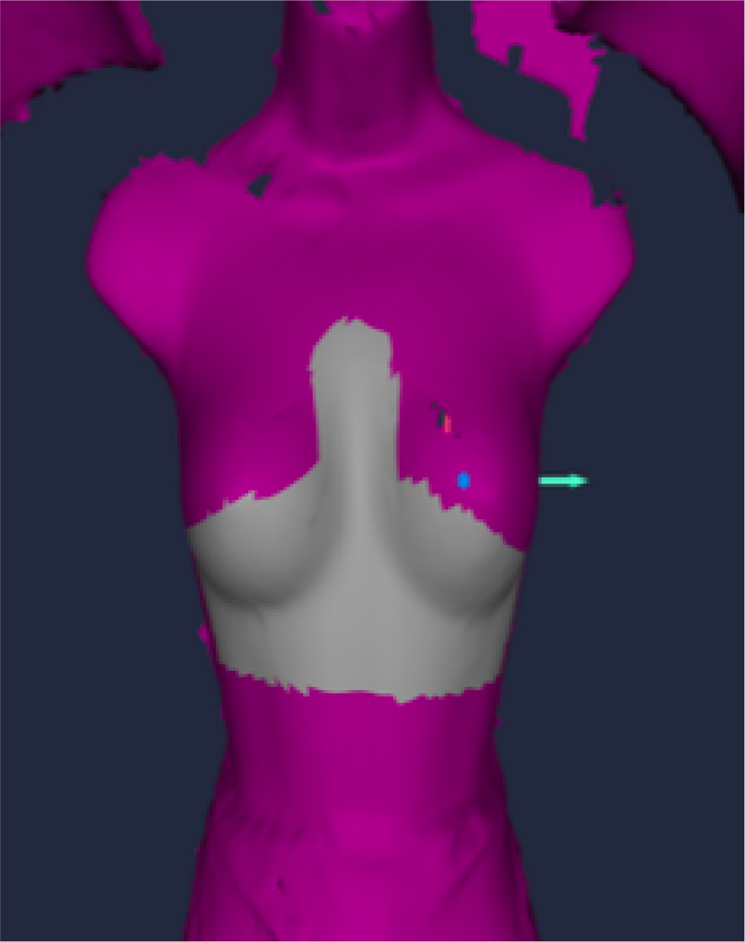
From these results, a monitoring ROI for rotational imaging and treatment has been suggested. This ROI may combine ROI_T and ROI_WBFC and include a band across the ribs below breast tissue extending superiorly to cover the inferior aspect of breast tissue. A strip would also be drawn down the sternum, and the ROI would extend laterally across to the midcoronal plane, with an example drawn in Figure 9. Jones et al. Reference Jones, Webster, Ntentas, Brady and Mikhaeel23,Reference Jones, Webster, Ntentas, Brady and Mikhaeel24 have altered the standard breast ROI to exclude superior lateral ROI aspects for DIBH mediastinal lymphoma patients to ensure ROI visibility during CBCT and VMAT treatment arcs, providing support for this ROI.
An example of an ROI for rotational imaging and treatment which excludes the superior lateral aspects of breast tissue, combining features of both ROI_WBFC and ROI_T.

Limitations
The results for approximate percentage ROI occlusion used a 2D screenshot for a 3D surface with the Sketch and Calc software. This reduces the validity of results as the ROIs extend laterally around a patient’s contour to the midcoronal plane, which was not wholly represented in the 2D analysis. Future research should use 3D surface analysis where possible.
Moreover, despite recommendations from both ESTRO-ACROP Reference Freislederer, Batista and Öllers7 and AAPM Reference Al-Hallaq, Cerviño and Gutierrez8 guidelines to use an anthropomorphic phantom, this does not represent all types of breast cancer patients, where breast/chest tissue can be a very deformable area post-surgery. This is coupled with variable body habitus, skin tones and types of surgical intervention which are not assessed in this evaluation as the phantom was smaller than average human anatomy and front-form only. This evaluation is limited by using one non-deformable static phantom and requires further research on a patient cohort of variable characteristics to increase the validity of results.
Additionally, only one vendor and model of linear accelerator was used: Elekta Versa HD (Elekta Ltd, Crawley, UK), with XVI CBCT equipment and using VisionRT’s AlignRT software. It has been reported anecdotally that the impact of camera occlusion can vary depending on the type of linear accelerator used, 18 likely due to differences in the dimensions of the machines and associated imaging equipment. The results for this evaluation are therefore limited to a single-vendor environment, and the impact of camera occlusion between vendors warrants further investigation.
Future recommendations
Results suggest an alternative ROI for rotational treatments, as displayed in Figure 9. This ROI could be used after using a set-up ROI to allow continuous monitoring. As CBCT is used as the gold standard image verification, the importance of the ROI is greater weighted to stable continuous monitoring as corrections are applied post-CBCT matching. Additionally, angles of occlusion for both the CBCT and arc should be recorded at fraction 1 utilising Figure 3 to ensure operators are aware of where occlusion may occur.
The type of CBCT preset, including the start/stop angles, acquisition time and length of travel, should be optimised. Altering the start/stop angles of the treatment arc may also be beneficial if practical to reduce travel through high risk of occlusion angles. Treatment arcs may also utilise partial/split arcs Reference Huijskens, Granton and Fremeijer3,Reference Al-Hallaq, Cerviño and Gutierrez8 or a flattening filter-free delivery Reference Koivumäki, Heikkilä, Väänänen, Koskela, Sillanmäki and Seppälä25,Reference Rudat, Shi, Zhao and Yu26 to decrease treatment times and further reduce time of gantry travel through high risk of camera occlusion angles.
Moreover, where camera occlusion cannot be corrected for by amending the ROI or CBCT/arc gantry angles, it may be appropriate to utilise the beam hold delay function 12 (Figure 8). This function stops beam gating for up to 3 seconds even when deltas fluctuate outside set tolerances. However, this feature should be used cautiously as the patient is not monitored by SGRT during occlusions with beam hold delay selected, and future research may investigate the safety and practicality of this function.
Conclusion
This preliminary technical evaluation of SGRT for VMAT CBCT DIBH breast patients has demonstrated gantry angles where there may be a greater risk of camera occlusion occurring between 10 and 60 degrees. A clinical workflow has been suggested to assist with problem-solving during camera occlusion. It is recommended that operators can assess for camera occlusion prior to imaging and treatment delivery using this guidance and record this appropriately. Additionally, results suggest the use of an ROI which excludes the superior lateral aspects of breast tissue to mitigate the impact of camera occlusion. Future research should confirm the robustness of this ROI by using a patient cohort of differing body habitus, particularly post-surgery and/or reconstruction and skin tones.
Acknowledgements
We would like to thank the Christie NHS Foundation Trust and the University of Liverpool for their support with this work.
Funding statement
This work was supported by the Christie NHS Foundation trust as part of a master’s module at the University of Liverpool.
Competing interests
No conflicts of interest were identified.



 Open access

