1. INTRODUCTION
Plasma wakefield acceleration (PWFA), laser driven (Faure et al., Reference Faure, Glinec, Pukhov, Kiselev, Gordienko, Lefebvre, Rousseau, Burgy and Malka2004; Geddes et al., Reference Geddes, Toth, van Tilborg, Esarey, Schroeder, Bruhwiler, Nieter, Cary and Leemans2004; Mangles et al., Reference Mangles, Murphy, Najmudin, Thomas, Collier, Dangor, Divall, Foster, Gallacher, Hooker, Jaroszynski, Langley, Mori, Norreys, Tsung, Viskup, Walton and Krushelnick2004; Leemans et al., Reference Leemans, Gonsalves, Mao, Nakamura, Benedetti, Schroeder, Tóth, Daniels, Mittelberger, Bulanov, Vay, Geddes and Esarey2014), and particle driven (Hogan et al., Reference Hogan, Barnes, Clayton, Decker, Deng, Emma, Huang, Iverson, Johnson, Joshi, Katsouleas, Krejcik, Lu, Marsh, Mori, Muggli, O'Connell, Oz, Siemann and Walz2005; Blumenfeld et al., Reference Blumenfeld, Clayton, Decker, Hogan, Huang, Ischebeck, Iverson, Joshi, Katsouleas, Kirby, Lu, Marsh, Mori, Muggli, Oz, Siemann, Walz and Zhou2007), has proven to be a possible alternative to conventional accelerators due to the intense electric fields that the plasma can sustain.
Among the configurations feasible for beam-driven plasma wakefield, a renewed interest is devoted to the use of modulated drivers in view of the forthcoming AWAKE experiment at CERN (Assmann et al., Reference Assmann, Bingham, Bohl, Bracco, Buttenschon, Butterworth, Caldwell, Chattopadhyay, Cipiccia, Feldbaumer, Fonseca, Goddard, Gross, Grulke, Gschwendtner, Holloway, Huang, Jaroszynski, Jolly, Kempkes, Lopes, Lotov, Machacek, Mandry, McKenzie, Meddahi, Militsyn, Moschuering, Muggli, Najmudin, Noakes, Norreys, Oz, Pardons, Petrenko, Pukhov, Rieger, Reimann, Ruhl, Shaposhnikova, Silva, Sosedkin, Tarkeshian, Trines, Tuckmantel, Vieira, Vincke, Wing and Xia2014). The goal of the project is to prove the possibility to employ the 400 GeV proton bunches produced at the super proton synchrotron (SPS) as drivers for the plasma wakefield.
The success of the experiment relies on the capability to produce short bunches whose length is approximately L = λp/4, being λp the plasma wavelength, from the much longer proton bunches provided at the SPS. Such achievement can be fulfilled through the self-modulation instability (Kumar et al., Reference Kumar, Pukhov and Lotov2010), in which the interaction of a long bunch with the wave itself leads to a modulation of the driver resulting in a train of bunches with the required length and periodicity approximately λp.
One issue of such a framework, and more in general for a PWFA with a pre-modulated beam, is the stability of the driver. A periodicity of λp provides an intense accelerating field, but does not guarantee as well a long-lasting driver, deteriorated by the defocusing transverse wakefield. Such a problem requires an analysis of the evolution of a modulated train of bunches interacting with a plasma.
The equilibrium and stability of a train of bunches has been deeply analyzed (Breizman et al., Reference Breizman, Chebotaev, Kudryavtsev, Lotov and Skrinsky1997; Lotov, Reference Lotov1998), including a broad range of effects such as neutralization of the driver current by electrons plasma drift and relativistic reduction of the plasma frequency in the non-linear regime.
In this work, we study the effects on the evolution of the driver, of the emittance-driven expansion of the front of the bunch. This problem, referred to as “emittance-driven erosion”, appears in different frameworks involving particle beams interacting with a plasma.
Previous works (Buchanan, Reference Buchanan1987; Krall et al., Reference Krall, Nguyen and Joyce1989; Barov & Rosenzweig, Reference Barov and Rosenzweig1994) addressed the problem in the context of beam transport in plasma in the ion-focused regime, studying the drift of the pinching point due to the emittance-driven expansion of the front of the bunch.
An analogous analysis has been performed in (Zhou et al., Reference Zhou, Clayton, Huang, Joshi, Lu, Marsh, Mori, Katsouleas, Muggli, Oz, Berry, Blumenfeld, Decker, Hogan, Ischebeck, Iverson, Kirby, Siemann and Walz2007; An et al., Reference An, Zhou, Vafaei-Najafabadi, Marsh, Clayton, Joshi, Mori, Lu, Adli, Corde, Litos, Li, Gessner, Frederico, Hogan, Walz, England, Delahaye and Muggli2013) in the framework of PWFA in the blowout regime with a field-ionized plasma. In this case, has been explored the effects of the head erosion on the drift of the ionization front.
In this paper, we address the problem of the stability of a train of bunches affected by the emittance-driven erosion. The drift of the pinching point affects the stability of the whole modulated beam due to the dependence of the beam slice dynamics by the upstream part (Breizman et al., Reference Breizman, Chebotaev, Kudryavtsev, Lotov and Skrinsky1997). The expansion of the front therefore involves an evolution of the whole beam configuration.
The goal of this paper is to mitigate the effects of the emittance erosion, by optimizing the proper periodicity of the modulated beam in order to improve its stability without severely affecting the resulting accelerating field.
We show that is possible to reduce the deterioration of the modulated driver caused by the head erosion, by properly placing the single bunches in a similar fashion as in (Breizman et al., Reference Breizman, Chebotaev, Kudryavtsev, Lotov and Skrinsky1997; Lotov, Reference Lotov1998). The larger number of bunch particles contributing to the wakefield will end up eventually in a more intense accelerating field as compared to the case of a modulation of λp, after few meters of propagation.
While in the case of a pre-modulated driver the new profile is easily achievable by properly configuring the spacing between the bunches, for a self-modulated driver like the AWAKE one, a different approach is necessary. A possible solution is the use of a non-uniform plasma density, with a density step at the stage of instability growth (Caldwell et al., Reference Caldwell, Adli, Amorim, Apsimon, Argyropoulos, Assmann, Bachmann, Batsch, Bauche, Berglyd Olsen, Bernardini, Bingham, Biskup, Bohl, Bracco, Burrows, Burt, Buttenschon, Butterworth, Cascella, Chattopadhyay, Chevallay, Cipiccia, Damerau, Deacon, Dirksen, Doebert, Dorda, Elsen, Farmer, Fartoukh, Fedosseev, Feldbaumer, Fiorito, Fonseca, Friebel, Geschonke, Goddard, Gorn, Grulke, Gschwendtner, Hansen, Hessler, Hillenbrand, Hofle, Holloway, Huang, Huther, Jaroszynski, Jensen, Jolly, Joulaei, Kasim, Keeble, Kersevan, Kumar, Li, Liu, Lopes, Lotov, Lu, Machacek, Mandry, Martin, Martorelli, Martyanov, Mazzoni, Meddahi, Merminga, Mete, Minakov, Mitchell, Moody, Muller, Najmudin, Noakes, Norreys, Osterhoff, Oz, Pardons, Pepitone, Petrenko, Plyushchev, Pozimski, Pukhov, Reimann, Rieger, Roesler, Ruhl, Rusnak, Salveter, Savard, Schmidt, von der Schmitt, Seryi, Shaposhnikova, Sheng, Sherwood, Silva, Simon, Soby, Sosedkin, Spitsyn, Tajima, Tarkeshian, Timko, Trines, Tueckmantel, Tuev, Turner, Velotti, Verzilov, Vieira, Vincke, Wei, Welsch, Wing, Xia, Yakimenko, Zhang and Zimmermann2015). Simulations showed that the proper change in the plasma density provides an arrest of the driver evolution just after it got fully modulated (Lotov, Reference Lotov2011, Reference Lotov2015).
The paper is structured as follows: in Section 2, we trace the model used for description of the interaction of Gaussian bunches with a plasma, assuming a linear response and the quasi-static approximation; in Section 3, we describe the evolution of the equilibrium configuration for the bunches emerging from the model, comparing the results with the case of flat-top bunches; in Section 4, we look for the proper position of the bunches in order to increase their stability without seriously affecting the longitudinal electric field; in Section 5, we present our conclusions.
2. ANALYTICAL MODEL
The model describing the interaction of a particle beam with plasma relies on the work of Kenigs and Jones (Reference Kenigs and Jones1987).
The authors consider an axi-symmetric bunch linearly interacting with an overdense plasma with immobile ions. Since the plasma is overdense, the beam is regarded as an external perturbation. The analysis is developed in the co-moving frame defined by the variables ξ = βct − z and τ = t with β = v b/c ≃ 1, v b being the beam velocity and c the speed of light. Lastly the quasi-static approximation is assumed, providing ∂τ ≃ 0.
The two-dimensional (2D) transverse and longitudinal fields arising from the interaction are then:
 $$\eqalign{W(r,{\rm \xi} ) & = (E_{\rm r} - {\rm \beta} B_{\rm \theta} ) = 4{\rm \pi} k_{\rm p}\int_0^\infty \int_0^{\rm \xi} \displaystyle{{\partial {\rm \rho} ({r}^{\prime},{{\rm \xi} ^{\prime}})} \over {\partial {r}^{\prime}}} \cr & \quad {r}^{\prime}I_1(k_{\rm p}r_ \lt )K_1(k_{\rm p}r_ \gt )\sin [k_{\rm p}({\rm \xi} - {{\rm \xi} ^{\prime}})]d{{\rm \xi} ^{\prime}}d{r}^{\prime},} $$
 $$\eqalign{E_z(r,{\rm \xi} ) & = - 4{\rm \pi} k_{\rm p}^2 \int_0^\infty \int_0^{\rm \xi} {\rm \rho} ({{\rm \xi} ^{\prime}},{r}^{\prime}){r}^{\prime} \cr & \qquad {\rm I}_0(k_{\rm p}r_ \lt ){\rm K}_0(k_{\rm p}r_ \gt )\cos [k_{\rm p}({\rm \xi} - {{\rm \xi} ^{\prime}})]d{{\rm \xi} ^{\prime}}d{r}^{\prime},} $$
where k p = ωp/v b is the plasma wavenumber, ρ(r, ξ) is the bunch charge density, I 1/0 and K 1/0 are the modified Bessel functions and r </> = min/max (r, r′).
We study the fields excited by a bunch with a flat-top profile in the transverse direction:
 $${\rm \rho} (r,{\rm \xi} ) = n_{\rm b}q_{\rm b}\left( {\displaystyle{{r_0} \over {r_{\rm b}({\rm \xi} )}}} \right)^2H(r_{\rm b}({\rm \xi} ) - r)\,f\,({\rm \xi} )$$
with n b being the peak bunch density, q b the bunch charge, r 0 the initial bunch radius, r b(ξ) the radius of the beam-envelope, H the Heaviside function and f(ξ) the longitudinal bunch profile. The wakefields generated by such a distribution are therefore:
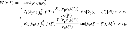 $$\eqalign{W(r,{\rm \xi} ) & = - 4{\rm \pi} k_{\rm p}n_{\rm b}q_{\rm b}r_0^2 \cr & \quad \left\{ \matrix{I_1(k_{\rm p}r)\int_0^{\rm \xi} f ({\rm \xi} ^{\prime})\displaystyle{{K_1(k_{\rm p}r_{\rm b}({\rm \xi} ^{\prime}))} \over {r_b({\rm \xi} ^{\prime})}} \hfill \sin [k_{\rm p}({\rm \xi} - {\rm \xi} ^{\prime})]d{\rm \xi} ^{\prime}r \lt r_{\rm b} \hfill \cr K_1(k_{\rm p}r)\int_0^{\rm \xi} f ({\rm \xi} ^{\prime})\displaystyle{{I_1(k_{\rm p}r_{\rm b}({\rm \xi} ^{\prime}))} \over {r_{\rm b}({\rm \xi} ^{\prime})}} \hfill \sin [k_{\rm p}({\rm \xi} - {\rm \xi} ^{\prime})]d{\rm \xi} ^{\prime}r \gt r_{\rm b}. \hfill} \right.}$$
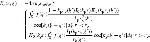 $$\eqalign{E_z(r,{\rm \xi} ) &= - 4{\rm \pi} k_{\rm p}n_{\rm b}q_{\rm b}r_0^2 \cr& \quad\left\{ \matrix{\int_0^{\rm \xi} f ({\rm \xi} ^{\prime})\displaystyle{{1 - k_{\rm p}r_{\rm b}({\rm \xi} ^{\prime})I_0(k_{\rm p}r)K_1(k_{\rm p}r_{\rm b}({\rm \xi} ^{\prime}))} \over {k_{\rm p}r_{\rm b}^2 ({\rm \xi} ^{\prime})}} \hfill \cr \quad\cos [k_{\rm p}({\rm \xi} - {\rm \xi} ^{\prime})]d{\rm \xi} ^{\prime}r \lt r_{\rm b} \hfill \cr K_0(k_{\rm p}r) {\int_0^{\rm \xi} f ({\rm \xi} ^{\prime})\displaystyle{{I_1(k_{\rm p}r_{\rm b}({\rm \xi} ^{\prime}))} \over {r_{\rm b}({\rm \xi} ^{\prime})}} \hfill \cos [k_{\rm p}({\rm \xi} - {\rm \xi} ^{\prime})]d{\rm \xi} ^{\prime}r \gt r_{\rm b}. \hfill}}\right.}$$
In order to self-consistently include the dynamics of the beam, we couple the fields equation with the beam-envelope equation for the beam radius assuming that the transverse motion of the beam can be described by only the motion of its boundary like in a water-bag model.
Denoting with r b = r b(ξ, τ) and with r b′ = r b(ξ′, τ), the resulting equation is:
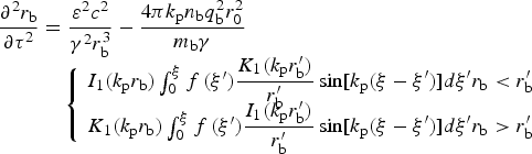 $$\eqalign{\displaystyle{{\partial ^2r_{\rm b}} \over {\partial {\rm \tau} ^2}} & = \displaystyle{{{\varepsilon} ^2c^2} \over {{\rm \gamma} ^2r_{\rm b}^3}} - \displaystyle{{4{\rm \pi} k_{\rm p}n_{\rm b}q_{\rm b}^2 r_0^2} \over {m_{\rm b}{\rm \gamma}}} \cr & \quad \left\{ {\matrix{ \matrix{I_1(k_{\rm p}r_{\rm b})\int_0^{\rm \xi} f\,({{\rm \xi}^{\prime}})\displaystyle{{K_1(k_{\rm p}r_{\rm b}^{\prime} )} \over {r_{\rm b}^{\prime}}} \hfill \sin [k_{\rm p}({\rm \xi} - {{\rm \xi} ^{\prime}})]d{{\rm \xi} ^{\prime}}r_{\rm b} \lt {{r}}_{\rm b}^{\prime} \hfill} \cr \matrix{K_1(k_{\rm p}r_{\rm b})\int_0^{\rm \xi} f\,({{\rm \xi} ^{\prime}})\displaystyle{{I_1(k_{\rm p}r_{\rm b}^{\prime} )} \over {r_{\rm b}^{\prime}}} \hfill \sin [k_{\rm p}({\rm \xi} - {{\rm \xi} ^{\prime}})]d{{\rm \xi} ^{\prime}}r_{\rm b} \gt {{r}}_{\rm b}^{\prime} \hfill} \cr}} \right.} $$
with ε being the normalized beam emittance,
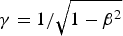 ${\rm \gamma} = 1/\sqrt {1 - {\rm \beta} ^2} $
the beam relativistic Lorentz factor, and m
b the mass of the beam particles.
From Eq. (6) results that the front of the beam is not subject to the wakefield and its dynamics is governed by the emittance-driven expansion according to the equation:
 $$r_{\rm b}({\rm \xi} = 0,{\rm \tau} ) = r_{{\rm b}0}({\rm \tau} ) = r_0\sqrt {1 + \displaystyle{{{\varepsilon} ^2c^2{\rm \tau} ^2} \over {r_0^4 {\rm \gamma} ^2}}}. $$
The purely diverging front of the bunch provides the absence of a global stable configuration for the transverse beam profile. Moreover, since the dynamics at every point along the bunch depends on the upstream part, the evolution of the front of the bunch leads to a change of the whole equilibrium configuration for the beam while propagating in the plasma.
It is worth noting that the effects of the emittance erosion can be mitigated by further physical effects not included in this model, guaranteeing so anyway a long-lasting train of bunches (Lotov, Reference Lotov1998).
3. EVOLUTION OF THE EQUILIBRIUM CONFIGURATION FOR GAUSSIAN BUNCHES
A previous work (Martorelli & Pukhov, Reference Martorelli and Pukhov2016) has analyzed the equilibrium configuration for a modulated bunch with longitudinal flat-top density profile. The authors have shown that the dynamics of the front of the bunch leads to a backward drift of the whole equilibrium configuration for the modulated beam.
We perform the same analysis for the case of bunches with a longitudinal Gaussian density profile. Since the defocusing force driven by the emittance does not depend on the shape of the bunch, we can expect a similar behavior as well for Gaussian bunches.
The analysis is developed by solving numerically, for every bunch slice, Eq. (4) for the desired longitudinal density profile. Once obtained the transverse field for the specific slice, we then evaluate the equilibrium radius as the global minimum of the potential providing Eq. (6), with the prescription r b(ξ, τ) ≤ r b(ξ = 0, τ). The algorithm is then repeated for every bunch slice.
First we consider the case of a modulated beam composed by identical equidistant bunches. The bunch densities are described by Eq. (3) with longitudinal profiles:
 $$f\,({\rm \xi} ) = \sum\limits_{\,j = 1}^N e^{ - {({\rm \xi} - {\rm \xi} _j)}^2/2{\rm \sigma} _j^2} = \sum\limits_{\,j = 1}^N e^{ - {({\rm \xi} - {\rm \xi} _0 - j\Delta )}^2/2{\rm \sigma} ^2}$$
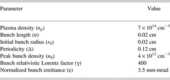
with N being the number of bunches, ξ j the center, σ j the length and Δ the periodicity. The complete set of the parameters characterizing both the plasma and the beam, with the exclusion of the beam length, is based on the baseline of the AWAKE project (Table 1).
Simulation parameters for plasma and bunch

Although this analysis refers explicitly to the AWAKE experiment, the mechanism that leads to the modulation can be general. Therefore, the same results hold for both a pre-modulated and a self-modulated beam.
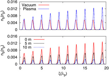
As expected (Fig. 1), the interaction with the plasma leads to the focusing of the modulated beam, increasing the peak density of the bunches as compared with the case of pure vacuum. The focusing force increases toward the tail of the configuration due to the interference among the transverse fields generated by the single bunches.
Quasi-equilibrium configuration for a modulated Gaussian bunch with periodicity 2λp in vacuum and in plasma (top) and for different propagation distances in the plasma (bottom).

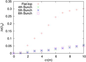
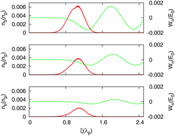
In order to avoid effects due to the overlapping of the single bunches, the periodicity has been set to Δ = 2λp. Studying the evolution of the equilibrium configuration for Gaussian bunches while propagating in the plasma, shows a behavior analogous to the case of flat-top bunches. The modulated beam tends to experience a backward shift in its equilibrium configuration, with the displacement that is increasing with the propagation distance. Nevertheless, as shown in Figure 2, the shift is much smaller for Gaussian bunches than that for flat-top ones. Although the backward shift is quantitatively different for the two cases, the reason is the same. The expansion of the front of the bunch corresponds to a decreasing bunch density and therefore a larger amount of bunch is required to obtain the same charge for different propagation distances. This process delays the onset of the focusing force (Fig. 3). The inhomogeneity of the Gaussian bunches tends anyway to a suppression of the fields, therefore the backward shift is less strong respect to flat-top bunches.
Shift of the 4th, 5th, and 6th bunch respect to its initial position varying the propagation distance in the plasma. The result is compared with the shift experienced by flat-top bunches.

Transverse field excited by a Gaussian bunch for 0, 5, and 10 m of propagation in the plasma.

This drift caused by the emittance-driven head erosion is qualitatively analogous to those studied in previous works (Buchanan, Reference Buchanan1987; Krall et al., Reference Krall, Nguyen and Joyce1989; Barov & Rosenzweig, Reference Barov and Rosenzweig1994; Zhou et al., Reference Zhou, Clayton, Huang, Joshi, Lu, Marsh, Mori, Katsouleas, Muggli, Oz, Berry, Blumenfeld, Decker, Hogan, Ischebeck, Iverson, Kirby, Siemann and Walz2007; An et al., Reference An, Zhou, Vafaei-Najafabadi, Marsh, Clayton, Joshi, Mori, Lu, Adli, Corde, Litos, Li, Gessner, Frederico, Hogan, Walz, England, Delahaye and Muggli2013). On the other hand, while in the previous works this effect was taken into account just for the analysis of the drift of the pinching point or of the ionization front, in the present analysis we look to how this drift affects the phase of the wakefield and therefore the evolution of a train of bunches initially in equilibrium.
This might be relevant also in context in which the emittance is nevertheless small enough to not provide any relevant deterioration of the driver compared with other physical effects (Lotov, Reference Lotov1998).
The emittance-driven evolution of the equilibrium configuration implies serious consequences for the stability and the duration of the modulated beam.
A bunch particle initially in an equilibrium position, will find itself in an unstable one while propagating in the plasma as a consequence of the rearrangement of the trapping potential caused by the expansion of the front.
The displacement experienced by the initial bunch radius with respect to the new equilibrium configuration results in a gain of transverse momenta. If the displacement is large enough, the bunch particles can even escape the trapping potential.
The more driver particles are depleted, the lower is the wakefield amplitude, resulting in the lower efficiency of the process.
It is worth underline that this is one mechanism of degradation of a periodic modulated driver. Full simulations have shown that the instability is caused by bunches partially falling into the defocusing phase of the wake (Lotov, Reference Lotov2015). Aim of this work nevertheless is the analysis of the instability caused by the emittance-driven head erosion.
4. OPTIMIZATION OF THE BEAM CONFIGURATION
The framework depicted previously demands a further analysis on the optimal configuration for a modulated beam in order to reduce its deterioration as much as possible, while propagating in the plasma.
A train of bunches with periodicity Δ = λp provides an intense accelerating field behind the driver, but the simple expansion of the front of the bunch causes its degradation. The more particles the bunches lose while propagating in the plasma, the weaker is the final accelerating field.
We look therefore to the proper position of the single bunches in order to maximize the number of particles keeping trapped while propagating in the plasma.
This is approach has been performed in previous works (Breizman et al., Reference Breizman, Chebotaev, Kudryavtsev, Lotov and Skrinsky1997; Lotov, Reference Lotov1998) including further physical effects in the analysis. We show here that also the phase-shift of the wakefield caused by the expansion of the head can be mitigated by finding a new proper configuration of the modulated beam by changing the periodicity of the bunches.
The trapping of the beam particles is studied between the initial and final position in the plasma channel. Since the backward shift increases with the propagation distance, improving the trapping respect to the final stage guarantees as well an improvement for the whole evolution.
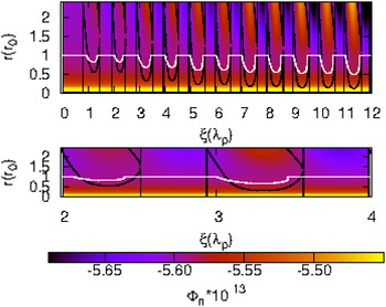
To establish which sections of the bunches are unstable, we compare the initial configuration with that at the end of the propagation. The bunch particles are lost if the difference between the two is large enough to provide the necessary transverse momentum to escape the trapping potential. In Figure 4, we can see an example of the method applied: some sections of the initial equilibrium configuration are, at the end of the propagation distance, out of the trapping region, meaning that those slices of the bunches are lost.
Potential surface after 10 m of propagation in the plasma. The white line corresponds to the equilibrium beam radius at 0 m, while the black lines are the boundaries for which the particle stay trapped after 10 m of plasma.

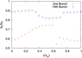
According to this criterion we look for the matching periodicity of the configuration that guarantees the highest number of particles trapped between the initial and final step. The procedure is performed for one bunch at the time, fixing the configuration upstream to the already evaluated matching positions.
In Figure 5, we can see the relative number of particles trapped changing the position of the last bunch of the configuration over a plasma wavelength.
Relative number of particles trapped after 10 m of propagation varying the position of the last bunch of the configuration.

As expected the maximum number of particles trapped is not achieved with a periodicity Δ = λp. This is a consequence of several aspects: The maximum of the Green function for the transverse field in Eq. (2) lies at Δ = λp/2; the Gaussian profile induces a non-linear shift of the maximum; the backward drift driven by the expansion of the front of the bunch causes an additional shift of the optimal position.
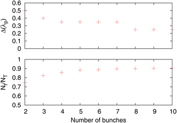
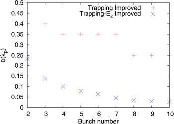
Moreover, as appears from Figure 6, the displacement is not constant for every bunch, meaning that it is not enough to rigidly move the configuration backward, but an analysis for every bunch is required. On the other hand the stability of the configuration, defined as the relative number of particles trapped, increases with the number of bunches involved. This is a consequence of the increasing total transverse field due to the superposition of the single ones generated by all the upstream bunches. Although this optimization provides an increasing final total charge of the beam, it does not necessarily imply as well an intense accelerating field behind the driver. The matching position improving the total charge can coincide with that providing a destructive interference of the accelerating field generated by the single bunches.
Matching position of every bunch to improve the trapping (top) and relative number of particles trapped (bottom).

This can be understood also by looking at Eq. (2), since the Green function for the longitudinal and transverse fields are π/2 out of phase, meaning that the maximum of the first will be close to the minimum of the second.
Therefore in order to obtain a configuration suitable for particle acceleration, it is necessary to improve the stability of the train of bunches without severely affecting the resulting longitudinal field behind the driver.
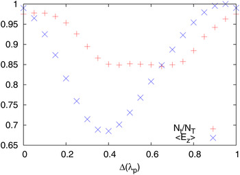
We perform an analogous analysis as the previous one, taking into account this time also the average of the accelerating field behind the driver over the propagation distance. The analysis is performed again for one bunch at the time, fixing the configuration upstream to the matching one.
Figure 7 displays clearly the behavior mentioned previously. The position that guarantees the maximum number of trapped particles does not correspond to that improving also the longitudinal field behind the driver. In order to obtain the better of the two behaviors, the matching condition is set at the crossing between the lines representing the relative number of trapped particles and the average accelerating field behind the driver (Fig. 8).
Relative number of trapped particles with average accelerating field behind the driver for a configuration with ten bunches.

Matching position of every bunch in order to improve both the stability of the driver and the final accelerating field. The result is compared with the previous one in which only the stability was guaranteed.

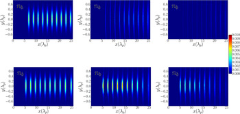
In order to confirm the results, we have performed a three dimensional particle in cell (PIC) simulation using the quasi-static VLPL code (Pukhov, Reference Pukhov2016). We compare both the bunch densities and the longitudinal electric field for a modulation of λp and the newly obtained modulation. We can see from Figure 9 that the optimized configuration preserves the bunch densities, obtaining a final charge higher than that in the periodic case.
Density of the modulated beam for a periodicity Δ = λp (upper line) and for the matching periodicity (lower line) at 0, 5, and 10 m in the plasma.

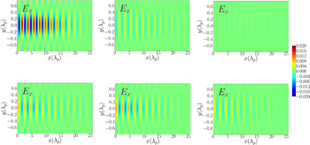
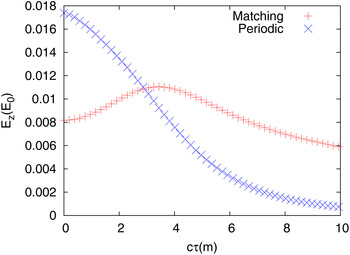
The longitudinal electric field as well provides the behavior expected by the improved configuration (Fig. 10). The modulation of λp guarantees a stronger electric field initially. On the other hand, the optimized configuration provides an improved focusing field acting on the single bunches. This leads to an increasing peak density and therefore an increasing accelerating field. After about 3 m of propagation in the plasma, the accelerating field behind the driver becomes stronger in the new configuration (Fig. 11) and the improved stability shows guarantees a slower decrease.
Longitudinal electric field generated by the modulated beam for a periodicity Δ = λp (upper line) and for the matching periodicity (lower line) at 0, 5, and 10 m in the plasma.

Comparison of the accelerating field behind the driver for the periodic and optimized cases as a function of the propagation distance.

5. CONCLUSION
In this work, we have analyzed the stability of a train of Gaussian bunches interacting with a plasma, a configuration occurring in PWFA employing pre-modulated or self-modulated beams.
Through a semi-analytical model we have study the equilibrium configuration for a series of periodic Gaussian bunches and the effects of the expansion of the front of the bunch in its evolution. The result shows an analogy with the backward shift occurring for flat-top bunches. To excite focusing fields of the same intensity for increasing propagation distances, it is required a longer section of the bunch, due to the decreasing density of the front. This provides a phase shift of the focusing field and therefore of the entire equilibrium configuration.
We pointed out as this backward shift leads to instability of the driver and to its deterioration while propagating in the plasma.
Through a numerical analysis we have found first the proper position of the bunches in order to mitigate the deterioration caused by the head erosion, improving the relative number of particles trapped during the propagation showing that is not provided by a periodicity of λp. We finally extended the analysis checking as well the resulting accelerating field behind the driver generated by the new configuration. The final result provides a configuration for a train of Gaussian bunches with an improved stability as well with a strong accelerating field behind the driver.
The validity of the analysis have been finally tested performing a 3D PIC simulation using the quasi-static VLPL code, providing the effects already observed in the simplified model. The accelerating field arising from the modified train of bunches is initially less intense than that emerging from a modulation of λp, but after about 3 m of propagation it becomes stronger, the difference between the two increasing further for the rest of the propagation distance.
ACKNOWLEDGMENTS
This work was founded by DFG TR18 and EuCARD2. The authors would like to thank Dr J. P. Farmer for useful discussions on the numerical aspects developed in this work.