1. Introduction: Shoulder exoskeleton
Upper-limb exoskeletons became increasingly vital in rehabilitation, assistance, and industrial enhancement. Among these, shoulder exoskeletons faced specific challenges due to the complex biomechanics and multi-axis motion associated with the shoulder complex. A central requirement in their development was the ability to accommodate anatomical motion while maintaining ergonomic alignment and functional assistance. This paper introduced a bio-mimetic design approach based on a spatial parallel mechanism (SPM), aiming to plan natural motion through a compact mechanical structure.
A thorough understanding of shoulder biomechanics was imperative in the design of upper-limb exoskeletons. The glenohumeral joint facilitated three rotational degrees of freedom (DOFs). However, functional arm elevation also depended on scapulothoracic rhythm and support provided by the acromio-clavicular joint [Reference Dalbøge, Frost, Grytnes, Roy, Samani and Christiansen1, Reference Hik and Ackland2]. Misalignment between robotic joints and anatomical joints compromised user comfort and diminished the effectiveness of assistance [Reference Atkins, Chang and Lee3–Reference Kim and Deshpande5]. These constraints motivated multiple design approaches that differed both in actuation philosophy and mechanical architecture.
Actuation approaches (passive and hybrid): Passive systems [Reference Dalbøge, Frost, Grytnes, Roy, Samani and Christiansen1, Reference Hyun, Bae, Kim, Nam and Lee6, Reference Pacifico, Scano, Guanziroli, Moise, Morelli, Chiavenna, Romo, Spada, Colombina, Molteni, Giovacchini, Vitiello and Crea7], including the Stuttgart Exo-Jacket [Reference Ebrahimi8], employed springs or elastic components to support shoulder motion with low power requirements. Hybrid methods, such as HERCULES [Reference Burns, Zavoda, Nataraj, Pochiraju and Vinjamuri9] and pneumatic-assisted systems [Reference Gull, Bak and Bai10, Reference Tsagarakis, Caldwell and Medrano-Cerda11], improved motion generation while reducing the complexity of fully motor-driven wearable assemblies. Although such approaches were effective for low-power assistance, they typically faced limitations in dynamic adaptability across users and tasks. In parallel, early-stage FEA-guided methodologies for soft, muscle-inspired actuation concepts demonstrated how simulation could de-risk actuator sizing and compliance prior to prototyping [Reference Elsamanty, Eltayeb and Shalaby12].
Design philosophies (modularity and transparency): Modular exoskeletons facilitated configurations tailored to individual users [Reference Gupta, Agrawal and Singla13], while transparency-oriented designs emphasized comfort during interaction and responsiveness [Reference Shimoyama, Noda, Teramae and Nakata14, Reference Zimmermann, Küçüktabak, Farshidian, Riener and Hutter15]. Despite these advances, anatomical compatibility and misalignment remained persistent challenges, particularly when shoulder motion was approximated using simplified joint models or when the wearable structure imposed unintended constraints.
Architecture selection (serial vs parallel): Beyond actuation choice and interface design, wearable shoulder systems are commonly differentiated by their mechanical architecture. A considerable number of shoulder exoskeletons were modeled using serial link-based architectures [Reference Carignan, Liszka and Roderick16], where actuators were arranged sequentially to emulate complex joint movements. However, serial chains were often susceptible to cumulative alignment errors and positioning inaccuracies, which could lead to deviations from natural anatomical motion paths, especially under multi-DOF shoulder elevation.
Parallel mechanisms, widely adopted in industrial robotics [Reference Dasgupta and Mruthyunjaya17, Reference Nielsen and Roth18], offered high stiffness and coordinated multi-DOF capability that could be leveraged to improve anatomical compatibility in wearable applications. For instance, a parallel-actuated shoulder exoskeleton [Reference Hunt, Lee and Artemiadis19] reported improved dynamic performance, and the University of Maryland design [Reference Carignan, Liszka and Roderick16], incorporating scapular motion, highlighted the importance of anatomical tracking within rehabilitation settings. Nevertheless, compact integration and wearable system-level implementation remained nontrivial, particularly when targeting accurate coupled position–orientation motion with favorable conditioning properties [Reference Asy, Bayomy, El-Hussieny, Ishii and Elsamanty20].
Existing market solutions such as Ottobock shoulder Exo [Reference Maurice, Čamernik, Gorjan, Schirrmeister, Bornmann, Tagliapietra, Latella, Pucci, Fritzsche, Ivaldi and Babič21], Auxivo DeltaSuit [Reference Brunner, van Sluijs, Luder, Camichel, Kos, Bee, Bartenbach and Lambercy22], and AE4W [Reference Rossini, De Bock, Ducastel, Van De Velde, De Pauw, Verstraten, Lefeber, Geeroms and Rodriguez-Guerrero23] demonstrated the practical relevance of shoulder assistance in industrial and clinical environments. However, these systems still faced challenges in motion accuracy and adaptability under dynamic misalignment, motivating continued investigation of architectures that can provide anatomically compatible motion with compact packaging.
The proposed work presented the design and modeling of a 5-DOF SPM intended for shoulder assistance. The mechanism employed a universal-prismatic-spherical (UPS) leg configuration to enable multidirectional motion characteristic of shoulder articulation. The kinematic analysis encompassed closed-form inverse kinematics and a numerical forward-kinematics solution, together with velocity and acceleration modeling through rigid-body and Jacobian-based techniques. Additionally, an anatomical mapping strategy was presented to align mechanism actuation directions with targeted muscle line-of-action trends in a bio-inspired design sense. Validation of the kinematic model was performed through numerical implementation in Python using pose datasets corresponding to neutral, flexion, and abduction motions of the upper limb.
Full shoulder exoskeleton model showing torso attachment of the chest and shoulder enclosure and 5 actuation legs connecting chest attachment with then shoulder enclosure.

2. Methodology and biomechanical modeling
The proposed novel shoulder exoskeleton was modeled to emulate the sophisticated biomechanics of the human shoulder joint complex through a 5-DOF SPM. The proposed model intended to map actuator motion with that of the anatomical motion. This section elaborates on the inspiration behind the mechanisms’ geometric configuration and its analogy with respect to the shoulder complex motion and the individual pose analysis. Figure 1 illustrates the conceptual model of the proposed shoulder exoskeleton, based on an anatomical study conducted on a human cadaver by Garner et al. [Reference Garner and Pandy24].
Shoulder exoskeleton model showing torso and shoulder mounting points and 5 leg connections. Two planes are shown in blare outlined in blue. First Torso attachment plane containing the base point (
 $B_{f_{i}}$
) attachment locations. The second plane for shoulder attachment plane with the locations of the moving platform (
 $P_{m_{i}}$
) attachment points (where i=1,2,…5).

2.1. Spatial architecture and pose selection
The proposed shoulder exoskeleton can be classified as an SPM due to its unique geometric configuration. As illustrated by the CAD model tailored using SolidWorks in Figure 1, five actuation legs with a U-P-S joint link a moving platform (MP) (Structure enclosing the shoulder), which was mounted to the upper arm, to a base structure fixed to the torso. All five base mount points of the SPM are situated on a shared anatomical plane known as the torso attachment plane, whereas the points for attachment of the leg links on the platform establish a parallel yet spatially distinct shoulder attachment plane, as shown in Figure 2. This arrangement facilitates three-dimensional rotational and translational movements through the planned coordinated actuation of all 5 mechanism link legs, exemplifying the characteristics of a SPM.
For analytical purposes, a simplified wire-frame model was made to represent the proposed exoskeleton mechanism as seen in Figure 3 to capture the kinematic structure. This model delineates the two rigid mounting planes formed by the platform points and base points, connected by actuated links that are planned to mimic the coupled dynamics of muscle joint systems throughout the evaluations.
Wire-frame model of 5-DOF SPM used for analysis: (i) Showing the Cad Model with the Wire-frame highlighted on the shoulder attachment plane and torso attachment plane, (ii) wire frame extraction from the mechanism, and (iii) the final wire-frame for the mechanism analysis for the neutral pose.

For this work, we had focused on two key shoulder movements. Initially, the arm was in a rest position, which was simply the arm aligned with the torso, with the palm and fingers pointing towards the floor. This was taken as the Neutral pose. From the Neutral pose, as shown in Figure 3, we moved our arm in the coronal plane, or the front plane, until our palms crossed the shoulder level. That became our first pose for analysis, called the Abduction pose in Figure 4(a). Similarly, as seen in Figure 4(b), when we raised the hand parallel to the sagittal plane from the same neutral position until the palm crossed the shoulder level, this pose was called the Flexion pose.
Shoulder exoskeleton poses for (a) abduction pose of arm with: (i) Showing the shoulder exoskeleton with the mannequin, (ii) here the wire frame is extracted from the mechanism pose, and (iii) Wire-frame model of 5-DOF SPM used for analysis for abduction. Similarly, (b) flexion pose of arm with: (i) Showing the shoulder exoskeleton with the mannequin, (ii) the wire frame is extracted from the mechanism pose, and (iii) Wire-frame model of 5-DOF SPM used for analysis for flexion.

2.2. Biomechanical mapping and leg function
(i) Shoulder movers partitioned into five functional groups (G1–G5) for later mapping to the five legs. Colors encode groups consistently across panels. (ii) Aggregate (effective) line of action (LoA) direction for each group G1–G5. Each segment starts at the centroid of the group insertion set and points along the normalized sum of member unit direction vectors. The aggregate is used as a geometric guideline and is not force weighted. (iii) Neutral pose wire diagram of the five-leg exoskeleton showing the final leg layout between labeled base anchors
 $B_{1..5}$
and platform anchors
 $P_{1..5}$
.

Figure 5. Long description
Panel i: A 3D scatter plot shows the partitioning of shoulder movers into five functional groups (G1 to G5), with each group represented by a different color. The axes are labeled Y (mm), X (mm), and Z (mm). The plot includes various muscle groups, each assigned to one of the five groups, and lines indicating the direction of muscle actions. Panel ii: A 3D scatter plot displays the aggregate line of action (LoA) direction for each of the five groups (G1 to G5). Each segment starts at the centroid of the group insertion set and points along the normalized sum of member unit direction vectors. The axes are labeled Y (mm), X (mm), and Z (mm). Panel iii: A wire diagram of a five-leg exoskeleton in a neutral pose shows the layout of the legs between labeled base anchors and platform anchors. The axes are labeled Y (mm), X (mm), and Z (mm). The diagram includes labels for base points, base loop, platform points, platform perimeter, and the five legs connecting base points to platform points.
Shoulder motion arises from the combined contribution of the glenohumeral joint, the scapulothoracic articulation, and the clavicular linkage, which together produce coupled rotational and translational motion of the upper limb [Reference Dalbøge, Frost, Grytnes, Roy, Samani and Christiansen1, Reference Hik and Ackland2]. As a result, the humeral head follows a curvilinear path during arm elevation rather than a purely rotational trajectory. This behavior is clinically relevant because glenohumeral motion during elevation can include small but meaningful translations relative to the glenoid due to joint compliance, contact mechanics, and soft-tissue constraints. When an exoskeleton is modeled with a purely rotational shoulder approximation or implemented with an overconstrained kinematic coupling, these translations may be accommodated through interface slip or parasitic loading at the human–robot contact regions, which can increase perceived misalignment and discomfort during repeated motion.
To represent this shoulder behavior within a compact mechanism-design framework, a direction-based biomechanical mapping strategy is adopted. Major muscles contributing to shoulder motion are identified, and their anatomical lines of action are used to define five functional muscle groups. Each group is then represented by one aggregate line of action, which is used as a geometric direction guideline for one leg of the five-limb SPM. This mapping is used to preserve the dominant anatomical action directions at the geometric and kinematic level, and it is not intended to represent muscle recruitment or force-sharing behavior directly.
The aggregate muscle directions are first used as anatomy-inspired directional guides for the mechanism layout, and the final actuator-leg directions are then determined through CAD-based geometric feasibility and attachment-point selection. Based on these directional guides, candidate base and platform attachment regions are selected and adjusted in CAD to obtain a feasible five-leg arrangement with usable pose transitions and without geometric interference. In this process, the final leg lines are defined by the selected attachment pairs
 $B_i$
and
 $P_i$
, while the aggregate muscle directions provide the directional basis for their placement. The base-side attachment regions are selected near anatomically relevant skeletal landmark zones in the frame layout, including the clavicle, sternum, scapula, and iliac crest regions, to provide geometric support and routing feasibility. The platform-side attachment regions are selected on the upper-arm interface in locations consistent with major shoulder muscle insertion zones. In the resulting configuration, each mechanism leg is treated as a geometric actuator path inspired by the dominant muscle action direction. The prismatic element provides the variable leg length, and the universal and spherical joints allow reorientation of the leg during motion while reducing the likelihood of kinematic overconstraint at the interface. The grouping, aggregate directional construction, and resulting neutral-pose leg layout are summarized in Figure 5(i)–(iii), respectively.
2.3. Biomechanical mapping workflow
A geometric workflow is used to convert anatomical muscle-line information into directional design guidelines for the five-leg mechanism. First, three-dimensional origin and insertion coordinates of upper-limb muscles are collected from anatomical references in a common global frame [Reference Garner and Pandy24]. For each muscle, a straight segment is defined from origin to insertion, and the corresponding unit vector is used to represent its line-of-action direction.
The muscles relevant to shoulder motion are then partitioned into five functional groups intended to correspond to the five mechanism legs. In the present study, the groups are defined as G1 = [PMJs, DLTc, PMN], G2 = [DLTa, DLTc], G3 = [LTDi], G4 = [SUPR, TMJ, DLTs, TRClg, INFR, TMN, SBSC], and G5 = [CRCB, RMN, RMJt2, RMJt3], as shown in Figure 5(i).
For each group
 $g$
, the member muscle unit vectors are summed and re-normalized to obtain one aggregate direction, and the aggregate reference point is defined as the centroid of the insertion points of the muscles in that group. The aggregate direction and centroid are expressed as follows.
 \begin{align} \displaystyle \hat {\mathbf{u}}_g \;=\; \frac {\displaystyle \sum _{m\in g}\frac {\mathbf{I}_m-\mathbf{O}_m}{\lVert \mathbf{I}_m-\mathbf{O}_m\rVert }} {\left \lVert \displaystyle \sum _{m\in g}\frac {\mathbf{I}_m-\mathbf{O}_m}{\lVert \mathbf{I}_m-\mathbf{O}_m\rVert }\right \rVert }, \qquad \mathbf{x}_g \;=\; \frac {1}{|g|}\sum _{m\in g}\mathbf{I}_m \end{align}
Equal weighting is assigned to all member muscle direction vectors in the present study, and PCSA-based weighting is not applied. Accordingly, the aggregate directions are used as bio-inspired geometric guidelines and are not interpreted as force-weighted muscle resultants. The resulting aggregate directions are illustrated in Figure 5(ii).
The aggregate directions are then used as anatomy-informed directional guides during the mechanism layout stage. Candidate base and platform attachment locations are selected and iteratively adjusted in CAD to avoid geometric interference and to preserve feasible motion over the intended pose transitions. After feasible attachment points are finalized, each mechanism leg axis is defined by the line joining the labeled base and platform points
 $B_i$
and
 $P_i$
. Each leg
 $B_i \rightarrow P_i$
is then associated with the closest matching group aggregate direction in the neutral pose, subject to geometric feasibility. This step establishes the group-to-leg correspondence used in the mechanism layout and yields the neutral-pose wireframe shown in Figure 5(iii).
The final attachment pairs
 $B_i$
and
 $P_i$
are therefore determined by a combination of anatomical directional guidance and mechanism-feasibility constraints, rather than by direct muscle-force equivalence.
2.4. Joint layout and actuation strategy
A five limb spatial parallel architecture is used for the proposed shoulder mechanism. Each limb follows a UPS joint sequence between the torso side base and the MP attached to the upper arm. This joint arrangement is selected to provide the required geometric mobility at the platform and to reduce the possibility of kinematic over constraint at the human robot interface. The universal joint at the base allows two rotational freedoms that accommodate limb reorientation during motion. The spherical joint at the MP allows three rotational freedoms at the platform attachment. The prismatic element provides the controllable limb length coordinate used in the kinematic formulation.
The actuation requirement is expressed in a generalized manner for the present design and analysis study. A variable length prismatic element is required in each limb. This element is modeled as a controllable length input for kinematic analysis and as an axial force input for static force reasoning along the limb direction. This formulation maintains generality of the analysis and avoids restricting the study to a single actuator technology in the main modeling sections. Implementation-specific hardware choices are treated as part of the translation and validation pathway described in the Future Work section.
The MP is coupled to the upper arm through a humeral cuff interface that functions as an upper arm cuff. A hard base structure will have a padding layer between the parts forming the base and the human body. This interface is intended to secure the humerus region and distribute interaction loads. The schematic representation is used to communicate geometric connectivity, joint locations, and attachment point definitions.
3. Kinematic modeling and analysis: SPM-based shoulder exoskeleton
The concept discussed in the previous section lays the groundwork for the upcoming analyses related to kinematics and static forces. We start by analyzing the mobility of the mechanism. For that, let
 $C$
be a point fixed on the MP, chosen at the origin of the platform local reference frame
 $\{M_{\mathrm{Local}}\}$
(i.e.,
 $C \equiv M_{\mathrm{Local}}$
), as shown in Figure 6(a). The moving-platform twist referenced at
 $C$
is given by
 $\mathbf{V}$
. Each actuated linkage is of the UPS type, with base point
 $B_i$
, platform point
 $P_i$
, and unit leg direction
 $\mathbf{s}_i$
. The MP is attached to the upper arm through a humeral cuff interface (upper-arm cuff).
 \begin{align} \mathbf{V}= \begin{bmatrix} \boldsymbol{\omega }\\ \mathbf{v}_C \end{bmatrix} \in \mathbb{R}^6, \qquad \mathbf{s}_i= \frac {\mathbf{P}_i-\mathbf{B}_i}{\|\mathbf{P}_i-\mathbf{B}_i\|} \end{align}
By reciprocity to the passive joints, the spherical joint at
 $P_i$
forbids any transmitted moment at
 $P_i$
, and the universal joint at
 $B_i$
removes all moment components incompatible with its two orthogonal rotation axes. The only admissible external wrench is therefore a pure force along the leg line,
 \begin{align} \mathbf{f}_i=\lambda _i\,\mathbf{s}_i,\qquad \mathbf{m}_{P_i}=\mathbf{0},\quad \lambda _i\in \mathbb{R} \end{align}
which, when referenced at
 $C$
(the origin of
 $\{M_{\mathrm{Local}}\}$
), has screw coordinates
 \begin{align} \mathbf{W}_i= \begin{bmatrix} \mathbf{m}_{C,i}\\ \mathbf{f}_i \end{bmatrix} = \begin{bmatrix} \mathbf{r}_{CP_i}\times (\lambda _i\,\mathbf{s}_i)\\ \lambda _i\,\mathbf{s}_i \end{bmatrix} \end{align}
A twist is instantaneously admissible if it does no virtual work against the independent constraint wrenches, collecting these as Pfaffian 1-forms yields
 \begin{align} A\,\mathbf{V}=0,\qquad A\in \mathbb{R}^{r\times 6},\ \ r=\mathrm{rank}(A) \end{align}
For this 5-UPS architecture, the five limb pure-force wrenches span a one-dimensional constraint-wrench space at the platform, i.e., only a single independent pure-force constraint remains. Hence the constraint-wrench space is one-dimensional (
 $r=1$
) and
 \begin{align} \mathcal{M}=6-1=5 \end{align}
That is, three rotations and two translations are allowed, one translational component is blocked by the single pure-force constraint. When a subject-specific waypoint calibration rotates this blocked direction over the workspace, the Pfaffian remains rank 1 at each pose, so the count stays five [Reference Merlet25]. Same thing can be verified by the stand analysis of DOF by Grübler–Kutzbach:
 \begin{align} \mathrm{DOF} \;=\; \lambda \,(N-1-J)\;+\;\sum _{i=1}^{J} F_i\;-\;I \end{align}
where
 $\lambda =6$
(3D space),
 $N$
is the number of links including base and platform,
 $J$
is the number of joints,
 $F_i$
is the DOF of joint
 $i$
(U = 2, P = 1, S = 3), and
 $I$
is any additional independent holonomic constraint. For this mechanism
 $N=12\;(1\,\text{base}+1\,\text{platform}+5\times 2\,\text{telescoping links}),J=15\;(5\times (\text{U}+\text{P}+\text{S}))$
,
 $\sum F_i = 5\times (2+1+3)=30,\qquad I=1\;(\text{the single pure-force constraint}).$
That Results.
 \begin{align} \mathrm{DOF} \;=\; 6\,(12-1-15)+30-1 \;=\; -24+29 \;=\; \mathbf{5} \end{align}
Thus the architecture has five independent DOFs.
3.1. Forward kinematics of the 5-DOF spatial parallel mechanism
Forward kinematics for the proposed 5-DOF SPM for the shoulder exoskeleton focuses on computing the position and orientation of the MP(Motion of the arm) from known actuator lengths. The spatial parallel architectures were done by multiple closed chains, the resulting kinematic equations were nonlinear, and that was difficult to lend themselves to direct analytical solutions. Instead, a numerical solution strategy such as the Newton-Raphson approach was adopted for accurate and reliable convergence.
Mechanism components and notations
The kinematic model comprises the following components:
 $\mathbf{B}_{\mathbf{global}}$
: represents the global reference frame in the fixed base plane(Torso attachment plane) in Figure 6(a),
 ${\mathbf{M}_{\mathbf{local}}}$
: represents the local platform reference frame in Figure 6 on the platform plane (Shoulder attachment plane), Fixed Base Points
 ${(\vec{\textrm{B}}_{\textrm{f}_{\textrm{i}}})}$
: These were the coordinates of attachment points on the torso, known parameter, and were defined in the global reference frame Figure 6(a). Moving Platform Points
 ${(\vec{\textrm{P}}_{\textrm{m}_{\textrm{i}}})}$
: Local coordinates of the MP(on shoulder region) where actuators other ends were mounted in Figure 6(a). Those need to be transformed to the global frame. Leg Vectors
 ${(\vec{\textrm{S}}_{\textrm{i}})}$
: Vectors representing actuator links that connect each base point to its corresponding platform point. Actuator Lengths
 ${(\textrm{k}_{\textrm{i}})}$
: Prismatic joint lengths provided as inputs, as shown in Figure 6(a).
(a) Schematic of the 5-DOF spatial parallel mechanism showing base points, platform points, and actuator legs. (b) Transformation of a platform point from the local frame to the global frame using rotation and translation.

Coordinate transformation
To compute the position of each platform point in the global frame in Figure 6(b), a coordinate transformation using Euler angles and translation is employed:
 \begin{align} \, \vec{\kern-2pt P}_{m_{i},global} = R(\phi _x, \phi _y, \phi _z) \cdot \, \vec{\kern-2pt P}_{m_{i}} + \vec {p} \end{align}
Here,
 $\vec {p} = [ M_x, M_y, M_z ]^T$
is the position vector of the platform in the global coordinate system. In our case,
 $M_y$
is constrained (fixed), while
 $M_z$
is treated as a free variable, and
 $R(\phi _x, \phi _y, \phi _z)$
is the rotation matrix obtained from Euler angles, representing the orientation of the MP (shoulder) relative to the base. Based on the geometry of the mechanism imposes a constraint on each actuator leg, as shown in Figure 6(b):
 \begin{align} \, \vec{\kern-2pt S}_i = \, \vec{\kern-2pt P}_{m_{i},global} - \vec {B}_{f_{i}} \end{align}
The squared norm of this vector must match the square of the given actuator length, given by
 $Q_i=\|\, \vec{\kern-2pt S}_i\|^2-k_i^2=0$
, for the values of
 $i=1,2,\ldots ,5$
. Now, in expanded component-wise form we get
 $Q_i=(S_{i,x})^2+(S_{i,y})^2+(S_{i,z})^2-k_i^2=0$
. These five constraint equations form a nonlinear system in the five unknowns:
 $M_x, M_z, \phi _x, \phi _y, \phi _z$
, while
 $M_y$
remains fixed. Now we implemented the forward kinematics solution by the Newton–Raphson method. The formulated nonlinear system was solved by an iterative Newton–Raphson technique:
 \begin{align} \vec {x}^{(n+1)} = \vec {x}^{(n)} - J^{-1}(\vec {x}^{(n)}) \cdot Q(\vec {x}^{(n)}) \end{align}
where
 $\vec {x} = [ M_x, M_z, \phi _x, \phi _y, \phi _z ]^T$
was the current estimate of the unknowns,
 $Q(\vec {x})$
was the vector of constraint equations, and
 $J$
was the Jacobian matrix with elements:
 \begin{align} J_{ij} = \frac {\partial Q_i}{\partial x_j} \quad \text{where } x_j \in \{ M_x, M_z, \phi _x, \phi _y, \phi _z \} \end{align}
Hessian correction
If convergence becomes unstable or slow, a second-order correction using the Hessian matrix will be applied:
 \begin{align} H_{ij} &= \frac {\partial ^2 Q_i}{\partial x_j \partial x_k} \end{align}
 \begin{align} \Delta \vec {x}_H &= -H^{-1}(\vec {x}^{(n)}) \cdot \nabla Q(\vec {x}^{(n)}) \end{align}
The update rule then becomes:
 \begin{align} \vec {x}^{(n+1)} = \vec {x}^{(n)} - J^{-1}(\vec {x}^{(n)}) Q(\vec {x}^{(n)}) + \Delta \vec {x}_H \end{align}
Convergence criteria
The iteration is terminated once both of the following conditions are satisfied:
 \begin{align} \| Q(\vec {x}) \| \lt \epsilon _Q \quad \text{and} \quad \| \vec {x}^{(n+1)} - \vec {x}^{(n)} \| \lt \epsilon _x \end{align}
where
 $\epsilon _Q$
and
 $\epsilon _x$
denoted small user-defined tolerances. Once convergence was reached, the forward kinematics solution provided the platform position:
 $(M_x, M_z)$
with
 $M_y$
known and constant and the platform orientation:
 $(\phi _x, \phi _y, \phi _z)$
. This formulation offered a robust and structured approach to determining the pose of the exoskeleton platform based solely on actuator inputs.
3.2. Inverse kinematics of the 5-DOF spatial parallel mechanism
Inverse kinematics for the 5-DOF SPM is the process of computing actuator parameters that achieve a desired pose of the MP(Shoulder). In the context of the proposed shoulder exoskeleton, this translates to determining the required leg lengths for a specific arm configuration defined by the platform’s position and orientation in the global frame.
The goal of inverse kinematics was to compute the actuator leg lengths
 $k_i$
(for
 $i = 1,2,\dots ,5$
), along with their azimuthal and elevation angles, based on a given pose of the MP. The inverse kinematics problem was fully defined by the following known quantities as, Base Points
 $(\vec {B}_{f_{i}})$
for Fixed coordinates of the base frame attachments, located on the torso attachment plane (refer to Figure 6). The Platform Points
 $(\, \vec{\kern-2pt P}_{m_{i}})$
were the Coordinates of the platform attachments defined in the local frame of the MP. Now the Platform Pose was given by
 $\vec {p} = [M_x, M_y, M_z]^T$
, Position vector of the MP in the global frame. In our setup,
 $M_y$
was treated as fixed (constrained), while
 $M_z$
was variable. The
 $\vec {\phi } = [\phi _x, \phi _y, \phi _z]^T$
gave us the Euler angles describing orientation. To compute the required leg lengths, each platform attachment point must be first transformed into the global frame:
 \begin{align} \, \vec{\kern-2pt P}_{m_{i},global} = R(\phi _x, \phi _y, \phi _z) \cdot \, \vec{\kern-2pt P}_{m_{i}} + \vec {p} \end{align}
where
 $R$
was the rotation matrix based on the Z-Y-X Euler angle convention, and was given by
 $R = R_z(\phi _z) \cdot R_y(\phi _y) \cdot R_x(\phi _x)$
. Now the leg vector
 $\, \vec{\kern-2pt S}_i$
was computed by connecting the base point to the transformed platform point:
 \begin{align} \, \vec{\kern-2pt S}_i = \, \vec{\kern-2pt P}_{m_{i},global} - \vec {B}_{f_{i}} \end{align}
The actuator length is then the Euclidean norm of this vector:
 \begin{align} k_i = \| \, \vec{\kern-2pt S}_i \| = \sqrt {S_{i,x}^2 + S_{i,y}^2 + S_{i,z}^2} \end{align}
For characterization and implementation, the azimuthal and elevation angles were also computed. Azimuthal Angle
 $\theta _i$
was the angle between the projection of
 $\, \vec{\kern-2pt S}_i$
on the XY-plane and the X-axis, and the Elevation Angle
 $\phi _i$
was the angle between
 $\, \vec{\kern-2pt S}_i$
and its projection on the XY-plane. These were given by:
 \begin{align} \theta _i = \tan ^{-1}\left (\frac {S_{i,y}}{S_{i,x}}\right)\!; \qquad \phi _i = \tan ^{-1}\left (\frac {S_{i,z}}{\sqrt {S_{i,x}^2 + S_{i,y}^2}}\right ) \end{align}
These angular parameters help in defining the spatial direction of each actuator relative to the torso frame and are critical for mechanical alignment. These findings allow the system to precisely adjust the exoskeleton platform, enabling shoulder movements that mimic natural behavior for activities such as reaching and lifting. The model’s reliability and effectiveness are enhanced by its spatial parallel design and anatomical mapping, as demonstrated in earlier sections.
3.3. Kinematic singularity analysis
We analyzed kinematic singularities using a standard velocity–level framework for closed chains [Reference Merlet25–Reference Park and Kim27]. For each leg
 $i$
, we defined
 $r_i = p + R\,P_i - B_i$
(vector from base to platform), its unit direction
 $s_i$
, and the leg row
 $b_i = \big [s_i^\top \ \ (r_i \times s_i)^\top \big ]\in \mathbb{R}^{1\times 6}$
. Stacking
 $b_i$
yielded
 $B\in \mathbb{R}^{5\times 6}$
, which mapped the platform twist
 $t=\big [v^\top \ \omega ^\top \big ]^\top$
to normalized leg–length rates.
Because
 $M_y$
was a known, user-specific constant in our system, admissible instantaneous motions lived in the 5-DOF subspace
 $(M_x,M_z,\phi _x,\phi _y,\phi _z)$
. We therefore constructed a
 $6\times 5$
twist basis
 $N$
spanning that subspace and formed the task Jacobian
 $J=B\,N\in \mathbb{R}^{5\times 5}$
. To balance units between translation and rotation, we scaled angular rates by the characteristic length
 $L_c=\tfrac {1}{5}\sum _i \lVert r_i\rVert$
(equivalently,
 $N=\mathrm{diag}(1,1,1/L_c,1/L_c,1/L_c)\,N_{\!\text{raw}}$
) [Reference Merlet25, Reference Murray, Li and Sastry28].
Type-1 (actuation) test. A loss of rank of
 $J$
meant the five prismatic legs could not generate an arbitrary admissible platform twist [Reference Gosselin and Angeles26, Reference Park and Kim27]. We monitored the smallest singular value
 $\sigma _{\min }(J)$
and the condition number
 $\kappa (J)=\sigma _{\max }(J)/\sigma _{\min }(J)$
. We classified a pose as “near Type-1” if
 $\sigma _{\min }(J)\lt 10^{-5}$
or
 $\kappa (J)\gt 10^{4}$
.
Type-2 (constraint) test. Constraint singularities occurred when instantaneous constraints became linearly dependent [Reference Zlatanov, Bonev and Gosselin29, Reference Zlatanov, Fenton and Benhabib30]. With the subject constraint
 $A=\big [0\ 1\ 0\ 0\ 0\ 0\big ]$
, we stacked
 $\displaystyle C=\begin{bmatrix} B \\ A \end{bmatrix}\in \mathbb{R}^{6\times 6}$
and applied the same column scaling (angular columns divided by
 $L_c$
). We reported
 $\sigma _{\min }(C)$
and the projection residual
 $\alpha _{\mathrm{res}}=\big \lVert A_{\mathrm{sc}}\,(I - B_{\mathrm{sc}}^{+} B_{\mathrm{sc}})\big \rVert _2$
, which measured how redundant
 $A$
was with respect to
 $\mathrm{Row}(B)$
. As a cross-check we reported
 $\lvert A_{\mathrm{sc}}\,t_{\mathrm{null}}\rvert$
, where
 $t_{\mathrm{null}}$
was the right-singular vector of
 $B_{\mathrm{sc}}$
associated with its smallest singular value [Reference Zlatanov, Bonev and Gosselin29]. We classified “near Type-2” if
 $\sigma _{\min }(C)\lt 10^{-5}$
or
 $\alpha _{\mathrm{res}}\lt 10^{-5}$
.
Numerical safeguards. Near ill-conditioning, we used damped least squares (Levenberg–Marquardt) and step clipping in our Newton solves. When rotational alignment between point sets was required (like in neutral
 $\rightarrow$
pose mapping) we used the SVD-based Kabsch/Umeyama method [Reference Lawrence, Bernal and Witzgall31].
4. Static force analysis of the 5-DOF spatial parallel mechanism
The static force analysis provided insights into how actuator forces had to be distributed to maintain mechanical equilibrium in the exoskeleton during stationary postures or quasi-static tasks. In the case of a 5-DOF SPM, this analysis helped determine whether the actuator forces required to support the external load were within acceptable operational bounds and whether force distribution was balanced across all actuators.
This section explained how we computed the forces in the five actuators based on the external load (force and moment) acting on the MP. It included a formulation of equilibrium conditions, their matrix representation, and an advanced optimization-based approach to minimize actuator effort while respecting physical constraints.
The total force due to actuators had to exactly counterbalance the external force applied on the MP (primarily from gravity and payload):
 \begin{align} \sum _{i=1}^{5} \, \vec{\kern-2pt F}_i + \, \vec{\kern-2pt F}_{ext} = \vec {0} \end{align}
where
 $\, \vec{\kern-2pt F}_i = f_i \hat {S}_i$
,
 $f_i$
was the magnitude of the actuator force, and
 $\hat {S}_i$
was the unit vector along the leg direction. This ensured that there was no net translation of the platform in any direction. Each actuator force also produced a moment around the platform center due to its point of application. The total moment had to cancel the external moment acting on the platform:
 \begin{align} \sum _{i=1}^{5} \, \vec{\kern-2pt r}_i \times \, \vec{\kern-2pt F}_i + \, \vec{\kern-2pt M}_{ext} = \vec {0} \end{align}
Here,
 $\, \vec{\kern-2pt r}_i$
was the position vector from the center of the MP to the
 $i$
-th attachment point, and the cross product
 $\, \vec{\kern-2pt r}_i \times \, \vec{\kern-2pt F}_i$
gave the torque generated by each actuator. We represented the above equilibrium equations in matrix form to solve them numerically:
 \begin{align} \underbrace {\begin{bmatrix} \mathbf{J}_F \\ \mathbf{J}_M \end{bmatrix}}_{\mathbf{A}_{6\times 5}} \underbrace {\begin{bmatrix} f_1 \\ f_2 \\ f_3 \\ f_4 \\ f_5 \end{bmatrix}}_{\, \vec{\kern-2pt f}} = -\underbrace {\begin{bmatrix} \, \vec{\kern-2pt F}_{ext} \\ \, \vec{\kern-2pt M}_{ext} \end{bmatrix}}_{\vec {b}} \end{align}
Here,
 $\mathbf{J}_F$
(Force Jacobian) consisted of the direction cosines of the five actuator leg unit vectors.
 $\mathbf{J}_M$
(Moment Jacobian) contained the moment-arm cross product components
 $\, \vec{\kern-2pt r}_i \times \hat {S}_i$
for each actuator. A was the force Jacobian matrix.
 $\vec {b}$
was the external load matrix.
 $\, \vec{\kern-2pt f}$
was the actuator forces matrix. If the matrix
 $\mathbf{A}$
was full-rank and square, we could directly compute actuator forces using:
 \begin{align} \, \vec{\kern-2pt f} = \mathbf{A}^{-1} \vec {b} \end{align}
However, due to the redundant actuation (5 actuators for 6 DOFs of force/moment equilibrium),
 $\mathbf{A}$
was not square. This resulted in an under-determined system, meaning there were infinite possible solutions. We had to then apply an optimization strategy to find the most efficient solution.
4.1. Quadratic programming for force optimization
To identify an actuator force distribution that was both feasible and energy-efficient, we solved a constrained optimization problem where the objective was to minimize actuator effort.
Objective:
 \begin{align} \min _{\, \vec{\kern-2pt f}} \quad \frac {1}{2} \,\, \vec{\kern-2pt f}^T \mathbf{Q} \,\, \vec{\kern-2pt f} + \mathbf{c}^T \, \vec{\kern-2pt f} \end{align}
Here,
 $\mathbf{Q}$
was a diagonal matrix that penalized high forces based on actuator efficiency or power consumption, and
 $\mathbf{c}$
was a linear cost term used for balancing.
Efficient load distribution using weighted quadratic cost matrix
To encourage energy-efficient force sharing, we defined the quadratic cost matrix
 $\mathbf{Q}$
as:
 \begin{align} \mathbf{Q} = \text{diag} \left ( \frac {P_1}{F_{\text{max},1}^2}, \frac {P_2}{F_{\text{max},2}^2}, \dots , \frac {P_5}{F_{\text{max},5}^2} \right ) \end{align}
where:
-
•
 $P_i$
was the power consumption per Newton for actuator
$i$
.
-
•
$F_{\text{max},i}$
was the maximum force capacity for actuator
$i$
.


This ensured actuators that consumed more power or had lower capacity were penalized more heavily.
Updating
 $ \mathbf{c}$
to further balance load
The linear cost vector
 $\mathbf{c}$
could help distribute forces evenly or bias them away from heavily loaded actuators:
 \begin{align} \mathbf{c} = -\lambda \cdot \text{diag}(\mathbf{Q}) \cdot \, \vec{\kern-2pt f}_0 \end{align}
where
 $\lambda$
was a bias scaling factor and
 $\, \vec{\kern-2pt f}_0$
was an initial estimate of the force distribution.
Subject to:
 \begin{align} \mathbf{A} \,\, \vec{\kern-2pt f} &= \vec {b} \quad \text{(Equilibrium)} \end{align}
 \begin{align} \, \vec{\kern-2pt f}_{min} &\leq \, \vec{\kern-2pt f} \leq \, \vec{\kern-2pt f}_{max} \quad \text{(Actuator limits)} \end{align}
4.2. KKT-based lagrangian formulation and optimality conditions
To solve the above constrained optimization problem, we formulated the Lagrangian function:
 \begin{align} L(\,\, \vec{\kern-2pt f}, \boldsymbol{\lambda }, \boldsymbol{\nu }) = \frac {1}{2} \,\, \vec{\kern-2pt f}^T \mathbf{Q} \,\, \vec{\kern-2pt f} + \mathbf{c}^T \, \vec{\kern-2pt f} + \boldsymbol{\lambda }^T(\mathbf{A} \,\, \vec{\kern-2pt f} - \vec {b}) + \boldsymbol{\nu }^T (\mathbf{G} \,\, \vec{\kern-2pt f} - \mathbf{h}) \end{align}
The Karush-Kuhn-Tucker (KKT) conditions described the necessary conditions for optimality in this constrained optimization problem:
(1) Stationarity: The gradient of the Lagrangian with respect to
 $\, \vec{\kern-2pt f}$
had to be zero:
 \begin{align} \nabla _f L = \mathbf{Q} \,\, \vec{\kern-2pt f} + \mathbf{c} + \mathbf{A}^T \boldsymbol{\lambda } + \mathbf{G}^T \boldsymbol{\nu } = 0 \end{align}
This ensured that the cost was minimized while satisfying constraint forces.
(2) Primal feasibility: The solution had to satisfy the original equality and inequality constraints:
 \begin{align} \mathbf{A} \,\, \vec{\kern-2pt f} = \vec {b}, \quad \mathbf{G} \,\, \vec{\kern-2pt f} \leq \mathbf{h} \end{align}
This confirmed the actuator forces resulted in static equilibrium and were within operational limits.
(3) Dual feasibility: The Lagrange multipliers for inequality constraints had to be non-negative:
 \begin{align} \boldsymbol{\nu } \geq 0 \end{align}
This ensured only valid (non-negative) penalty weights were applied to limit violations.
(4) Complementary slackness: For each inequality constraint, either the constraint was active (tight) or the multiplier was zero:
 \begin{align} \boldsymbol{\nu }^T (\mathbf{G} \,\, \vec{\kern-2pt f} - \mathbf{h}) = 0 \end{align}
This condition ensured that only active constraints influenced the final solution.
Together, the KKT conditions provided a complete mathematical framework to ensure that the optimized actuator forces:
-
• Satisfied mechanical equilibrium (force and moment balance)
-
• Stayed within actuator force limits
-
• Minimized energy consumption or actuator load based on system efficiency
This formed the final step in a comprehensive and physically feasible static analysis for the 5-DOF exoskeleton mechanism.
5. Velocity and acceleration kinematics of the 5-DOF spatial parallel mechanism
With the foundation of static equilibrium and force distribution laid out, we then transitioned to modeling the system’s motion by formulating its kinematic relationships. This section focused on the velocity and acceleration kinematics of the MP, as governed by the 5-DOF SPM. These expressions were crucial for constructing the full dynamic model, where forces and torques varied with time in response to motion. The instantaneous motion of the MP was characterized by its linear and angular velocities. These were expressed in the global reference frame as:
 \begin{align} \dot {\vec {p}} = \begin{bmatrix} \dot {M}_x \\ \dot {M}_z \end{bmatrix}, \qquad \vec {\omega } = \begin{bmatrix} \dot {\phi }_x \\ \dot {\phi }_y \\ \dot {\phi }_z \end{bmatrix} \end{align}
The overall motion was collectively represented as a generalized velocity vector:
 \begin{align} \dot {\vec {X}} = \begin{bmatrix} \dot {M}_x \\ \dot {M}_z \\ \dot {\phi }_x \\ \dot {\phi }_y \\ \dot {\phi }_z \end{bmatrix} \end{align}
5.1. Leg velocity equations
Each actuator connected a fixed base point to a MP point via a leg vector
 $\, \vec{\kern-2pt S}_i = \, \vec{\kern-2pt P}_{m_i,global} - \vec {B}_{f_i}$
. Differentiating both sides with respect to time gave the leg velocity:
 \begin{align} \dot {\, \vec{\kern-2pt S}}_i = \dot {\, \vec{\kern-2pt P}}_{m_i,global} \end{align}
To express
 $ \dot {\, \vec{\kern-2pt P}}_{m_i,global}$
, we used the rigid body velocity equation:
 \begin{align} \dot {\, \vec{\kern-2pt P}}_{m_i,global} = \dot {\vec {p}} + \vec {\omega } \times \, \vec{\kern-2pt r}_i \end{align}
where
 $ \, \vec{\kern-2pt r}_i$
was the position vector of the platform attachment point relative to its center. Hence, the leg velocity was:
 \begin{align} \dot {\, \vec{\kern-2pt S}}_i = \dot {\vec {p}} + \vec {\omega } \times \, \vec{\kern-2pt r}_i \end{align}
Actuator velocity via projection
To determine the actuator velocity (change in leg length), we projected the leg velocity vector onto its own direction:
 \begin{align} \dot {k}_i = \hat {S}_i^T \left (\dot {\vec {p}} + \vec {\omega } \times \, \vec{\kern-2pt r}_i\right ) \end{align}
Stacking equations for all five actuators in matrix form gave:
 \begin{align} \dot {\vec {k}} = \mathbf{J}_v \dot {\vec {X}} \end{align}
where
 $ \dot {\vec {k}} = [\dot {k}_1, \dot {k}_2, \dot {k}_3, \dot {k}_4, \dot {k}_5]^T$
was the vector of actuator velocities, and
 $ \mathbf{J}_v$
was the Velocity Jacobian, given by:
 \begin{align} \mathbf{J}_v = \begin{bmatrix} \hat {S}_{1,x} & \quad \hat {S}_{1,z} & \quad \hat {S}_1^T [\, \vec{\kern-2pt r}_1]_\times \\ \hat {S}_{2,x} & \quad \hat {S}_{2,z} & \quad \hat {S}_2^T [\, \vec{\kern-2pt r}_2]_\times \\ \hat {S}_{3,x} & \quad \hat {S}_{3,z} & \quad \hat {S}_3^T [\, \vec{\kern-2pt r}_3]_\times \\ \hat {S}_{4,x} & \quad \hat {S}_{4,z} & \quad \hat {S}_4^T [\, \vec{\kern-2pt r}_4]_\times \\ \hat {S}_{5,x} & \quad \hat {S}_{5,z} & \quad \hat {S}_5^T [\, \vec{\kern-2pt r}_5]_\times \end{bmatrix} \end{align}
This Jacobian mapped platform velocity to actuator velocities. In cases where the matrix was full-rank and invertible, we could compute the platform velocity from actuator velocities via:
 \begin{align} \dot {\vec {X}} = \mathbf{J}_v^{-1} \dot {\vec {k}} \end{align}
Here,
 $ \mathbf{J}_a$
was the Acceleration Jacobian, with terms
 $ \frac {\, \vec{\kern-2pt S}_i^T}{k_i}$
and
 $ \frac {\, \vec{\kern-2pt S}_i^T [\, \vec{\kern-2pt r}_i]_\times }{k_i}$
, and
 $ \mathbf{C}(\vec {\omega })$
was the Centripetal acceleration term, derived from the double cross-product. This formulation fully described how the velocity and acceleration of the platform translated to the prismatic actuator rates. These relationships served as a bridge from purely kinematic modeling to dynamic analysis and simulation.
6. Results: Forward and inverse kinematics of the 5-DOF shoulder exoskeleton
This section presented an integrated analysis of both forward and inverse kinematics results for the 5-DOF shoulder exoskeleton. The three of the targeted representative poses – Neutral, Flexion, and Abduction – were analyzed based on the platform position and orientation as computed by forward kinematics and the corresponding actuator parameters (lengths and joint angles) from inverse kinematics. Visual overlays in 3D and 2D projections aided in understanding the spatial transformations and validating the numerical implementation.
6.1. Visualization of the neutral, flexion, and abduction poses
Figures 7 showed the 3D wireframe overlays of Neutral with Flexion and Abduction poses using forward kinematics. These overlays were complemented by 2D projections in Figures 8 and 9, providing orthographic perspectives.
-
• In the Flexion pose (Figure 7), the platform underwent a noticeable upward (Z-direction) and forward (Y-direction) shift. Platform attachment points 1 and 2 raised significantly in height, simulating natural anterior shoulder motion as seen in real-world deltoid flexion.
-
• In the Abduction pose (Figure 7), the transformation was predominantly in the lateral (X-direction) axis. Platform points 3, 4, and 5 spread further apart laterally and slightly elevated, accurately mapping to the human shoulder’s coronal-plane abduction.
3D wireframe overlays generated using forward kinematics. Left: Neutral to flexion transition showed a superior and anterior shift in platform points locations, representing forward arm motion. Right: Neutral to abduction transition demonstrated lateral divergence of
 $P_{m_{i}}$
, characterizing shoulder abduction. These visuals confirmed the geometric and anatomical fidelity of the exoskeleton’s motion modeling.

Figure 7. Long description
Two 3D wireframe overlays generated using forward kinematics. Panel A: Neutral to flexion transition showed a superior and anterior shift in platform points locations, representing forward arm motion. Panel B: Neutral to abduction transition demonstrated lateral divergence of platform points, characterizing shoulder abduction. These visuals confirmed the geometric and anatomical fidelity of the exoskeletons motion modeling.
2D orthographic projections for neutral to flexion transition. Left: XY view highlighted anterior shift. Middle: YZ view confirmed vertical lift. Right: XZ view showed combined forward-elevation curvature. The coordinated planar shifts mirrored physiological flexion.

6.2. 2D projections for forward kinematics transitions
The orthographic projections presented in Figures 8 and 9 allowed planar interpretation of movement trajectories. In the YZ projection of Figure 8, the vertical displacement confirmed the lifting of the arm during flexion. Similarly, Figure 9 showed a wider lateral dispersion of Platform points during abduction, indicating coronal-plane motion.
2D orthographic projections for neutral to abduction transition. Left: XY view highlighted lateral motion. Middle: YZ maintained vertical spread. Right: XZ showed lateral outward arc. These spatial transitions aligned with expected abduction kinematics.

Figure 9. Long description
Three line graphs depict orthographic projections of neutral to abduction transition in different views. Panel A: Top View (X-Z). The graph shows the lateral motion with X-axis labeled as X and Y-axis labeled as Z. The lines represent Base, Neutral, and Abduction with different colors. Panel B: Front View (X-Y). The graph shows the vertical spread with X-axis labeled as X and Y-axis labeled as Y. The lines represent Base, Neutral, and Abduction with different colors. Panel C: Side View (Y-Z). The graph shows the lateral outward arc with X-axis labeled as Y and Y-axis labeled as Z. The lines represent Base, Neutral, and Abduction with different colors.
6.3. Inverse kinematics validation of flexion and abduction poses
To validate the results of the forward kinematics, inverse kinematics was solved using the same MP pose configuration to generate actuator parameters. The generated 3D and 2D pose reconstructions (Figures 10 and 11, 12) closely matched the forward kinematics predictions. This provided strong evidence for both the numerical correctness and biomechanical consistency of the parallel mechanism implementation.
3D inverse kinematics validation overlays. Left: Flexion pose reconstruction based on inverse-calculated actuator lengths, showing excellent alignment with forward pose. Right: Abduction pose reconstruction from inverse kinematics, confirming accurate spatial reproduction of the forward model configuration

2D projections (XZ, XY, YZ) for inverse kinematics flexion pose. The MP point trajectories replicated forward kinematic displacement patterns across all projections.

Figure 11. Long description
Panel A: A line graph depicts the XZ view of inverse kinematics flexion pose. The horizontal axis is labeled X and the vertical axis is labeled Z. The graph includes two sets of points and lines: blue points and dashed lines labeled Base, and red points and dashed lines labeled Platform. The lines connect points labeled B1 to B5 for the Base and P1 to P5 for the Platform. Panel B: A line graph depicts the XY view of inverse kinematics flexion pose. The horizontal axis is labeled X and the vertical axis is labeled Y. Similar to Panel A, it includes blue points and dashed lines for the Base and red points and dashed lines for the Platform, with points labeled B1 to B5 and P1 to P5. Panel C: A line graph depicts the YZ view of inverse kinematics flexion pose. The horizontal axis is labeled Y and the vertical axis is labeled Z. It also includes blue points and dashed lines for the Base and red points and dashed lines for the Platform, with points labeled B1 to B5 and P1 to P5.
The spatial alignment of Platform points’ coordinates (Table I) confirmed geometric fidelity between forward and inverse kinematic computations. This alignment validated the consistency of the solvers, as well as the mapping accuracy of muscle-driven motions to actuator displacements.
6.4. Tabular comparison of forward and inverse kinematics results
Interpretative highlights:
-
• Validation consistency: Forward kinematics results (Table I) closely matched the inverse-reconstructed poses. No significant mismatches were observed between platform point positions, indicating the robustness of the numerical solver and proper geometric formulation.
-
• Biomechanical mapping: The increase in leg lengths and elevation angles in Flexion (Table III) corresponded with anterior lifting of the arm, consistent with deltoid-driven shoulder movement. In Abduction, lateral shifts aligned with scapular rotation and middle deltoid activation, with MP displacements matching expected muscle lines of action.
-
• Pose-specific contributions: Leg 3 and Leg 5 exhibited large elevation (Table II) changes in Abduction, indicating their dominant contribution to shoulder abduction. Conversely, in Flexion, Leg 1 and Leg 2 extended most prominently in vertical and anterior directions, mapping to anterior deltoid involvement.
-
• Kinematic symmetry and distribution: The observed symmetry in actuator responses across both sides of the platform confirmed the balanced configuration of the mechanism. Azimuth patterns showed that opposing legs counteracted platform torque.
Platform point coordinates (
 $P_{m_{i}}$
) in global frame for all three poses from the output of forward kinematics.

Table I. Long description
with three columns labeled Neutral, Flexion, and Abduction, each with sub-columns X, Y, and Z in millimeters. The table has six rows labeled P subscript a, P subscript b, P subscript c, P subscript d, P subscript e, and P subscript f. Each row contains three sets of coordinates corresponding to the Neutral, Flexion, and Abduction poses. Row 1: P subscript a, Neutral: X -42.06, Y -133.00, Z 124.49; Flexion: X 88.03, Y -78.88, Z 173.78; Abduction: X 9.65, Y -87.85, Z 168.53. Row 2: P subscript b, Neutral: X -74.66, Y -148.07, Z 31.94; Flexion: X 2.47, Y -127.23, Z 187.87; Abduction: X -23.24, Y -179.20, Z 147.79. Row 3: P subscript c, Neutral: X 117.79, Y -193.93, Z -42.96; Flexion: X 13.34, Y -228.44, Z 2.44; Abduction: X 126.13, Y -214.71, Z 2.27. Row 4: P subscript d, Neutral: X 136.77, Y -190.77, Z -14.95; Flexion: X 42.58, Y -216.40, Z -10.03; Abduction: X 133.42, Y -185.46, Z 3.18. Row 5: P subscript e, Neutral: X 152.80, Y -172.35, Z 81.28; Flexion: X -161.06, Y -8.62, Z 163.24; Abduction: X -93.63, Y 35.25.
Inverse kinematics output: actuator lengths and joint angles for flexion and abduction poses.

Table II. Long description
The presents data on actuator lengths and joint angles for flexion and abduction poses. It has five rows and eight columns. The columns are labeled as follows: Leg, Length (mm), Azimuth (°), Elevation (°), Length (mm), Azimuth (°), Elevation (°). The rows are labeled as Leg 1, Leg 2, Leg 3, Leg 4, and Leg 5. Row 1: Leg 1, Length 267.48, Azimuth -29.91, Elevation 27.14, Length 171.60, Azimuth -59.57, Elevation -1.57. Row 2: Leg 2, Length 283.05, Azimuth -48.82, Elevation 39.68, Length 225.22, Azimuth -32.89, Elevation -3.96. Row 3: Leg 3, Length 293.43, Azimuth -116.31, Elevation 52.55, Length 382.14, Azimuth -49.98, Elevation 68.05. Row 4: Leg 4, Length 210.83, Azimuth -120.52, Elevation -5.26, Length 207.75, Azimuth -84.74, Elevation 41.92. Row 5: Leg 5, Length 240.14, Azimuth -105.29, Elevation -48.64, Length 217.33, Azimuth -115.05, Elevation 5.19.
2D projections (XZ, XY, YZ) for inverse kinematics abduction pose. All planar views confirmed spatial fidelity with expected forward-generated configuration.

6.5. Singularity results for abduction and flexion
We evaluated the indices from Section 3.3 at both target poses using the FK (Newton–Raphson) solutions and the prescribed IK poses. The 3D overlays of reconstructed platforms against the base and the neutral configuration were shown in the figures above. Table III listed the IK-pose indices. The FK indices computed at the same poses led to the same “near”/“not-near” classification under the thresholds in the caption and were therefore omitted for brevity.
Abduction.
 $(M_x,M_y,M_z)=(51.40,-161.84,83.08)\,\mathrm{mm}$
,
 $(\phi _x,\phi _y,\phi _z)=(\!-43.31^\circ ,41.83^\circ ,20.13^\circ )$
yielded
 $\kappa (J)=1.42\times 10^{12}$
,
 $\sigma _{\min }(J)=2.49\times 10^{-14}$
and, for the constraint stack,
 $\sigma _{\min }(C)=5.67\times 10^{-19}$
,
 $\alpha _{\mathrm{res}}=9.05\times 10^{-5}$
,
 $\lvert A\,t_{\mathrm{null}}\rvert =1.62\times 10^{-17}$
.
Flexion.
 $(58.02,-161.84,83.87)\,\mathrm{mm}$
,
 $(\!-49.72^\circ ,70.00^\circ ,-25.38^\circ )$
yielded
 $\kappa (J)=1.45\times 10^{12}$
,
 $\sigma _{\min }(J)=6.22\times 10^{-14}$
and
 $\sigma _{\min }(C)=3.34\times 10^{-18}$
,
 $\alpha _{\mathrm{res}}=7.16\times 10^{-5}$
,
 $\lvert A\,t_{\mathrm{null}}\rvert =2.48\times 10^{-17}$
.
Both poses lay in near-singular neighborhoods for Type-1 (actuation) and Type-2 (constraint). The very large
 $\kappa (J)$
and tiny
 $\sigma _{\min }(J)$
indicated severe actuation ill-conditioning, while the small
 $\sigma _{\min }(C)$
with
 $\alpha _{\mathrm{res}}\sim 10^{-4}$
indicated the
 $M_y$
constraint was almost, but not exactly, redundant with the five leg constraints. This agreed with classical classifications for closed-chain singularities. Inverse-kinematics pose indices and thresholds used for “near” classification.
Inverse-kinematics poses with singularity indices (scientific notation). Near type-1 if
 $\sigma _{\min }(J)\!\lt \!10^{-5}$
or
 $\kappa (J)\!\gt \!10^{4}$
. Near type-2 if
 $\sigma _{\min }(C)\!\lt \!10^{-5}$
or
 $\alpha _{\mathrm{res}}\!\lt \!10^{-5}$
.

Table III. Long description
A table comparing kinematic parameters for two poses, Abduction and Flexion. The table has 2 rows and 8 columns. The columns are labeled as follows: Pose, M_x (mm), M_y (mm), M_z (mm), φ_1 (°), φ_2 (°), φ_3 (°), κ (J), and σ_κ (J). The row labels are Abduction and Flexion. Row 1: Abduction, M_x, 51.40; M_y, -161.84; M_z, 83.08; φ_1, -43.31; φ_2, 41.83; φ_3, 20.13; κ, 1.42 x 10^12; σ_κ, 9.05 x 10^-5. Row 2: Flexion, M_x, 58.02; M_y, -161.84; M_z, 83.87; φ_1, -49.72; φ_2, 70.00; φ_3, -25.38; κ, 1.45 x 10^12; σ_κ, 7.16 x 10^-5.
7. Results: Velocity and acceleration analysis of the 5-DOF shoulder exoskeleton
Building upon the validated kinematic configurations derived in the previous section, this section presents the results of the velocity and acceleration analysis for the 5-DOF shoulder exoskeleton. The time-dependent simulation of transitions between poses, Neutral to Flexion and Neutral to Abduction, was used to evaluate platform-level velocities and accelerations along with actuator velocities (
 $\dot {k}_i$
) and accelerations (
 $\ddot {k}_i$
). These results provided insight into motion smoothness, pose-dependent actuation demand, and biomechanical consistency.
7.1. Platform velocity and angular velocity profiles
Sinusoidal interpolation of the moving-platform pose was used to generate time-varying platform center
 $\vec {p}(t)$
and orientation. From this, the platform linear velocity
 $\dot {\vec {p}}(t)$
and angular velocity
 $\boldsymbol{\omega }(t)$
were computed. Figure 13 shows the platform velocity components for both transitions. The profiles remained smooth and continuous, with the expected sign reversal around mid-transition due to the sinusoidal trajectory. The dominant components reflected the intended motion planes, where abduction emphasized lateral and elevation directions, while flexion emphasized elevation combined with forward motion. The angular velocity components followed the same trend, indicating that the platform rotation was consistent with the target pose change.
Platform velocity results from sinusoidal interpolation. Panel (a) shows the neutral to abduction transition and panel (b) shows the neutral to flexion transition. In each panel, (i) shows platform linear velocity components and (ii) shows platform angular velocity components.

The corresponding actuator velocity demands are shown in Figure 14. The velocity magnitudes differed across legs depending on the transition, confirming pose-dependent participation driven by the mechanism geometry. Despite these differences, the actuator responses remained synchronized with the platform motion, indicating coordinated motion generation without trajectory discontinuities.
Actuator velocity profiles
 $\dot {k}_i(t)$
during sinusoidal transitions. Panel (a) shows the neutral to abduction transition and panel (b) shows the neutral to flexion transition.

Figure 14. Long description
Panel A: A line graph titled Actuator Velocities k_i(t) (Neutral to Abduction Transition) shows actuator velocity in millimeters per second on the vertical axis and time in seconds on the horizontal axis. The graph includes five lines representing Leg 1, Leg 2, Leg 3, Leg 4, and Leg 5. Each line shows different trends over time, with some lines increasing, decreasing, or fluctuating. Panel B: A line graph titled Actuator Velocities k_i(t) (Neutral to Flexion Transition) also shows actuator velocity in millimeters per second on the vertical axis and time in seconds on the horizontal axis. This graph similarly includes five lines for Leg 1, Leg 2, Leg 3, Leg 4, and Leg 5, each displaying distinct trends over time.
7.2. Platform acceleration and actuator acceleration profiles
Platform linear acceleration
 $\ddot {\vec {p}}(t)$
and angular acceleration
 $\boldsymbol{\alpha }(t)$
were obtained by differentiating the corresponding velocity quantities. Figure 15 shows the platform acceleration components for both transitions. The acceleration profiles remained bounded and continuous, and the peak magnitudes occurred in the higher-effort portions of the trajectory as expected from a smooth sinusoidal motion. The dominant acceleration directions matched the same plane-wise interpretation observed in the velocity results.
Platform acceleration results from sinusoidal interpolation. Panel (a) shows the neutral to abduction transition and panel (b) shows the neutral to flexion transition. In each panel, (i) shows platform linear acceleration components and (ii) shows platform angular acceleration components.

The actuator acceleration profiles
 $\ddot {k}_i(t)$
are shown in Figure 16. These results highlighted the actuator effort zones, where rapid motion changes required higher prismatic acceleration capability. The same legs that showed higher velocity demand generally exhibited higher acceleration demand during the transition. Overall, the absence of abrupt spikes supported feasibility for controlled real-time implementation and provided stable second-order kinematic inputs for subsequent dynamic modeling.
Actuator acceleration profiles
 $\ddot {k}_i(t)$
during sinusoidal transitions. Panel (a) shows the neutral to abduction transition and panel (b) shows the neutral to flexion transition.

Figure 16. Long description
Two line graphs depict actuator acceleration profiles during sinusoidal transitions. Panel A shows the neutral to abduction transition, while Panel B shows the neutral to flexion transition. Each graph has a horizontal axis labeled Time in seconds ranging from 0 to 2.0 seconds and a vertical axis labeled Actuator Acceleration in mm per second squared ranging from -300 to 300 in Panel A and -800 to 800 in Panel B. The graphs display data for five legs, each represented by a different colored line: Leg 1 in blue, Leg 2 in green, Leg 3 in purple, Leg 4 in pink, and Leg 5 in yellow. Panel A shows varying acceleration patterns for each leg during the neutral to abduction transition, with peaks and troughs at different times. Panel B shows similar varying acceleration patterns for each leg during the neutral to flexion transition, with higher acceleration values compared to Panel A.
7.3. Interpretation and biomechanical implications
-
• Pose-dependent platform behavior: The platform velocity and acceleration components showed distinct dominance patterns for abduction versus flexion, reflecting the expected coronal-plane versus sagittal-plane nature of these motions (Figures 13 and 15).
-
• Pose-dependent actuator participation: The actuator velocity and acceleration profiles showed that different legs contributed more strongly depending on the transition, consistent with the spatial arrangement of the UPS legs and the direction of required platform motion (Figures 14 and 16).
-
• Smoothness and feasibility: All platform and actuator kinematic quantities remained smooth and continuous, and no discontinuities were observed. This supported trajectory feasibility for real-time implementation and provided stable inputs for the next stage of modeling.
Note: These velocity and acceleration results form the quantitative basis for subsequent dynamic modeling and actuator-level control design. While dynamic forces were not included in this stage, the kinematic profiles confirmed smooth motion generation and pose-dependent actuation demand aligned with the intended shoulder movements.
8. Results: Static force analysis of the 5-DOF shoulder exoskeleton
To evaluate the quasi-static mechanical feasibility of the proposed 5-DOF shoulder exoskeleton, we performed a detailed static force analysis under three configurations: Neutral Pose, Abduction Pose, and Flexion Pose. For each pose, three force computation strategies were compared: basic static equilibrium, relaxed quadratic minimization (unweighted), and full KKT-based quadratic programming optimization that incorporated actuator efficiency weights.
Actuator force comparison for neutral, abduction, and flexion poses across three approaches: unoptimized static solution (light blue), relaxed quadratic optimization (cyan), and KKT-based quadratic programming (green). Forces are shown for legs 1 to 5. red and green dotted lines indicate lower and upper pneumatic actuator limits (
 $\pm$
100 N). The KKT approach consistently achieved balanced force sharing and reduced peak loads.

Interpretation and biomechanical relevance
-
• Unoptimized static forces: As seen in Figure 17, the direct solution of the static equilibrium equations led to significantly high force magnitudes in certain legs, particularly Legs 2 and 5. In the neutral pose, for instance, Leg 2 exhibited tensile forces beyond –110 N, exceeding actuator safety margins. This unbalanced distribution was a consequence of the underactuated nature of the 5-DOF parallel mechanism, where the static solution was not unique or optimal.
-
• Relaxed optimization (Minimum norm solution): When applying a relaxed quadratic minimization approach (minimizing
$\|\, \vec{\kern-2pt f}\|^2$
), the force demands were spread more evenly across actuators. However, as this method lacked actuation efficiency weighting, it could still overload actuators with relatively lower capacity. -
• KKT-based optimization: The full KKT-based quadratic programming solution considered both mechanical constraints and actuator efficiency. As shown in green in Figure 17, this method achieved the best load-sharing performance, keeping all actuator forces well within
$\pm$
100 N. This demonstrated the practical viability of the exoskeleton in delivering joint torques without mechanical overload. -
• Biomechanical mapping: Legs 2 and 5 consistently bore high loads across all poses in the unoptimized solution. This mirrored the physiological role of the anterior deltoid and coracobrachialis in shoulder flexion and abduction. The KKT approach enabled biomechanical realism by simulating muscle-like cooperation, distributing load analogously to human synergistic muscle activation.
-
• Implications for operation and safety: The results strongly advocated for embedded optimization in real-time operation to maintain actuator loads within operational thresholds. By reducing the reliance on any single actuator, the KKT-based strategy also enhanced mechanical robustness and reduced the risk of overuse in wearable applications.
-
• Design insights: The reduced peak force under KKT optimization supported the selection of compact, energy-efficient actuators. Furthermore, the improved force symmetry suggested that symmetric actuator placement and equal load-bearing capability were optimal design features for the shoulder exoskeleton.


9. Discussion
9.1. Comparative benchmarking and positioning
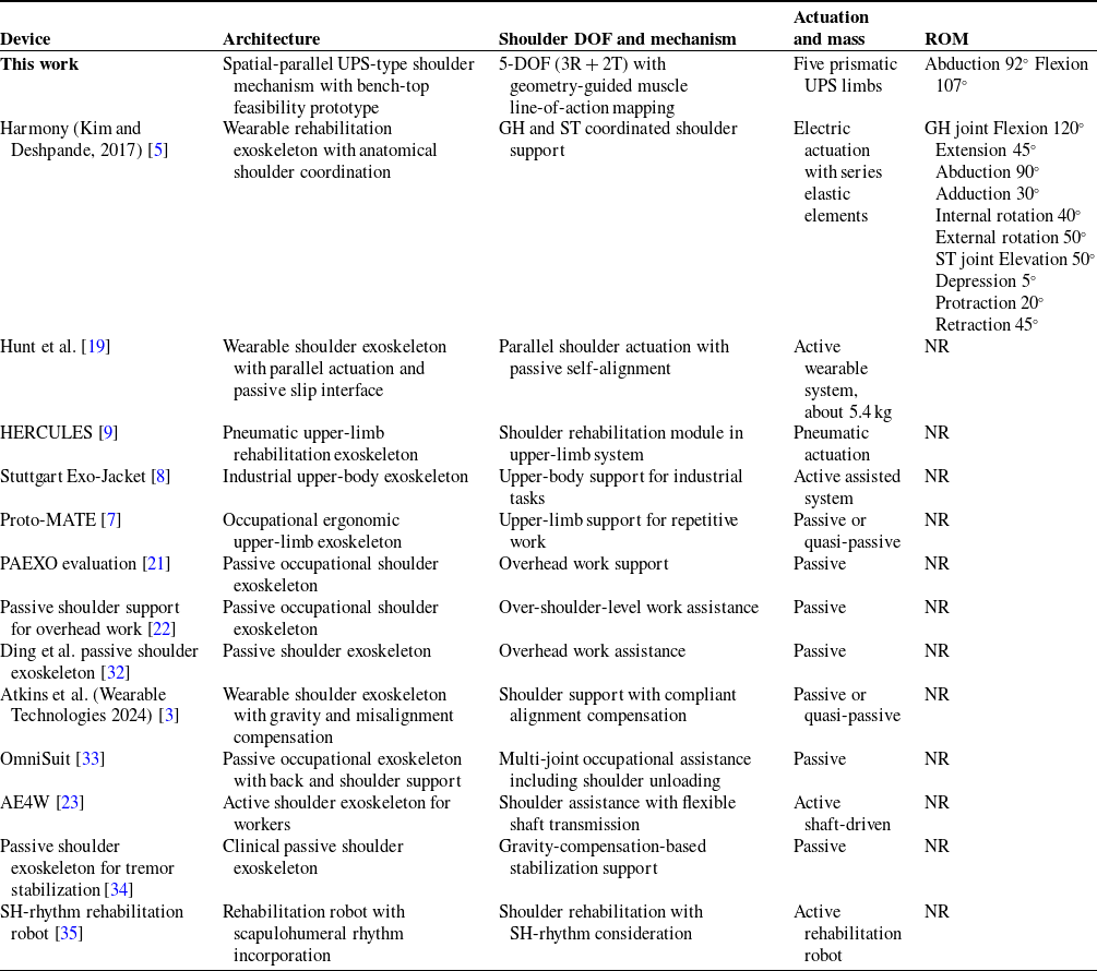
The proposed system differs from most reported wearable devices (as shown in Table IV) because it is formulated as a spatial-parallel shoulder mechanism with a 5-DOF shoulder-platform motion and a geometry-guided muscle line-of-action mapping strategy. Many occupational exoskeleton studies focus on passive support effectiveness, user comfort, and task performance. Many rehabilitation robots focus on therapy delivery, control design, and clinical outcomes. A direct one-to-one comparison of mechanism-level kinematic properties and shoulder ROM is therefore not always possible across the available literature.
A simulation-driven assessment of the proposed shoulder exoskeleton mechanism was carried out using the spatial-parallel kinematic framework. A five-limb UPS architecture was adopted to represent the actuatorized linkage structure and to evaluate whether multi-axial shoulder motion could be reproduced within a constrained and mechanically realizable arrangement. The velocity and acceleration analyses were performed using trajectory interpolation between neutral, abduction, and flexion poses. The results showed smooth platform motion and physically consistent actuator responses over the analyzed movements.
Comparison of representative shoulder and upper-limb exoskeleton systems with the proposed 5-DOF spatial-parallel shoulder exoskeleton. NR indicates that a numerical device ROM is not explicitly reported in the cited source.

Table IV. Long description
Table with multiple rows and columns detailing different shoulder exoskeleton devices. Columns include Device Name, Mechanism and Mass, Range of Motion (ROM), Application, Actuation Type, and Reference. Each row describes a specific device, such as Passive shoulder support for overhead work, Passive occupational shoulder exoskeleton, and Wearable shoulder exoskeleton with gravity and misalignment compensation, among others. The table provides information on the type of actuation (Passive, Active, or NR), the mechanism and mass, and the specific application of each device.
The actuator kinematic trends observed across the analyzed motions were mechanically interpretable. During abduction, stronger participation was observed in specific limbs located in the lateral and posterior portions of the mechanism. This behavior is consistent with the geometric directionality assigned during the biomechanical mapping step. During flexion, a different set of limbs became dominant and this reflects the expected directional redistribution during the shoulder pose transition.
The static-force analysis highlighted the importance of force distribution across the five limbs. In non-optimized configurations, elevated loads were concentrated in a subset of legs and this indicated the risk of uneven actuator demand and localized overload. When relaxed and KKT-based optimization strategies were applied, a more balanced distribution was obtained. This is favorable for practical actuator sizing and for reducing peak loading within the mechanism.
Although the present study demonstrates kinematic feasibility and improved static-force distribution through optimization, several next-stage developments remain important for translational deployment. Dynamic modeling with full moving-mass effects and actuator dynamics is needed to quantify transient loading and control bandwidth requirements. Subject-specific interface design and alignment refinement will be needed to reduce donning variability and improve anatomical conformity. Broader workspace characterization and singularity-aware trajectory planning should also be incorporated to ensure robust operation over a wider range of upper-limb tasks.
Overall, the study supports the feasibility of the proposed spatial-parallel architecture as a shoulder-motion testbed for further development. The present results establish the kinematic and static-force foundation for subsequent work on dynamic modeling, control design, workspace characterization, and subject-specific wearable implementation.
10. Future work
While the kinematic and static analyses confirmed the validity and feasibility of the exoskeleton design, several key aspects remained to be explored:
-
• Dynamic modeling and control: A natural extension of this work was the development and implementation of a dynamic model incorporating inertial, gravitational, and Coriolis effects. This would facilitate the design of feedback control strategies and trajectory planning algorithms that were essential for real-time operation.
-
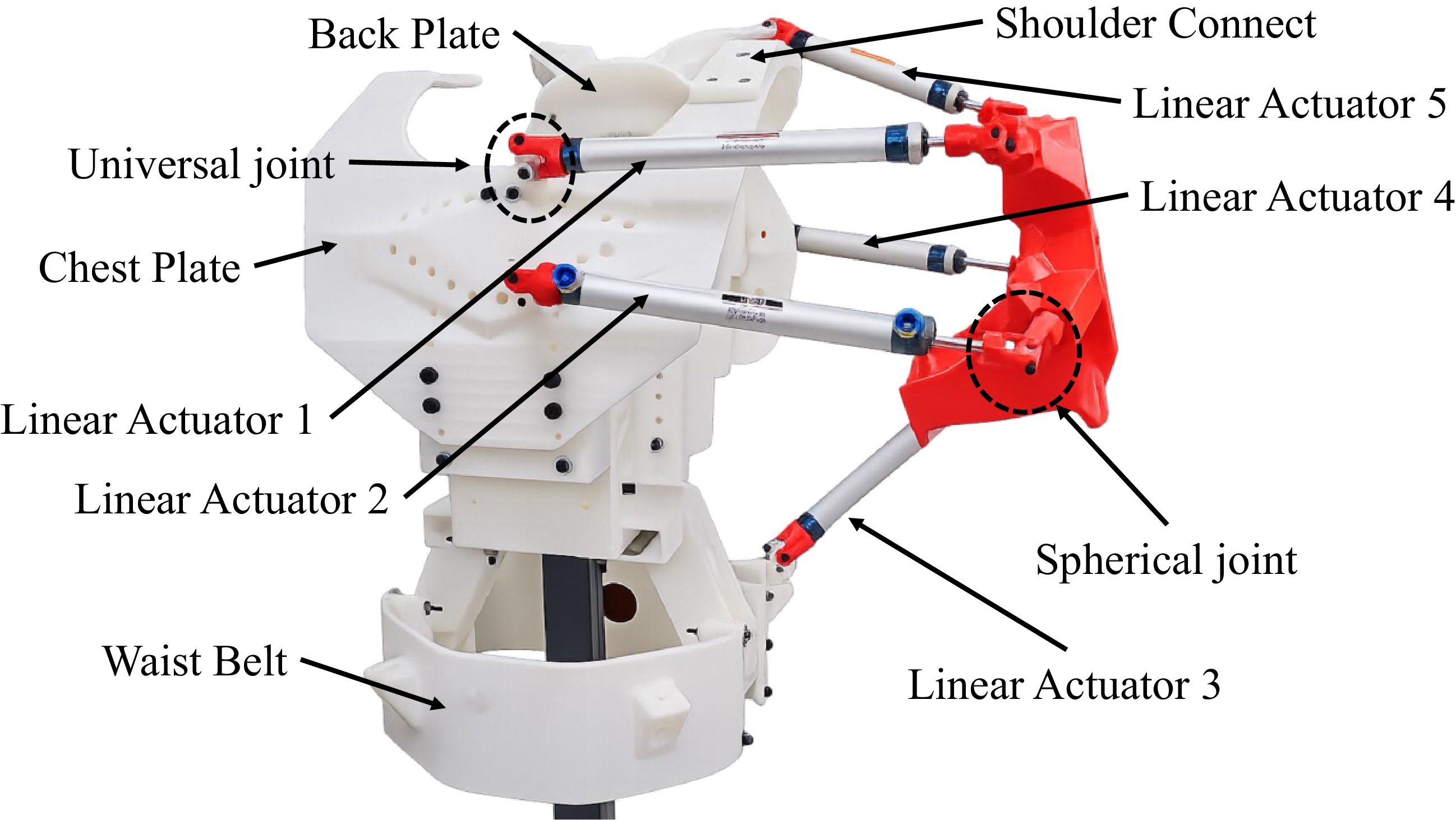
• Prototype fabrication and experimental validation: Although the present paper does not report fabrication procedures or experimental performance metrics, an initial prototype effort has been initiated as part of the forward translation of the proposed concept. As an early feasibility configuration to begin hardware exploration, five pneumatic cylinders were selected (three with 150 mm stroke and two with 80 mm stroke), with an initial rated load of approximately 10 kg per cylinder for first-stage evaluation. A photograph of the preliminary prototype assembly is provided in Figure 18 to document the ongoing transition from analysis to implementation, without treating hardware testing outcomes as results of this study.
-
• Integration with human musculoskeletal models: Future versions of this model could be co-simulated with biomechanical simulation platforms (e.g., OpenSim or AnyBody) to better align actuator loading with biological muscle actions and to ensure ergonomic safety.
-
• Sensor integration and real-time feedback: Incorporating IMUs, force sensors, and pressure transducers would enable responsive adaptation to user motion and external loads. This was especially relevant for rehabilitation scenarios.
-
• Personalization for anatomical variability: Further study was needed to generalize the actuator placement and attachment strategy across users with different anthropometric characteristics. Adaptive calibration or user-specific tuning algorithms might be required.
These future directions aimed to transition the current theoretical model into a practical and deployable assistive system.
Preliminary prototype assembly initiated as part of ongoing future-work activities.

10.1. Planned experimental validation & timeline
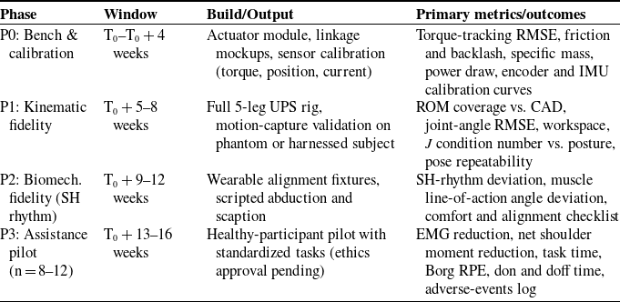
Staged hardware validation is planned (in Table V) to quantify mechatronic performance, kinematic and biomechanical fidelity (including scapulohumeral rhythm), and human-in-the-loop assistance outcomes. Institutional ethics approval would be obtained prior to any human testing.
Prototype builds. (i) Bench-top actuator module and instrumented linkage (3D-printed mockups allowed) for torque, velocity, and friction tests. (ii) Full 5-leg UPS spatial-parallel rig with adjustable base and instrumented end-effector. (iii) Wearable harness with adjustable alignment fixtures for safe donning.
Primary metrics and acceptance targets.
-
• Mechatronic: torque-tracking RMSE (as % of peak command), static friction and breakaway torque, backlash and hysteresis, steady-state speed error, specific mass (kg per N
$\cdot$
m), and average and peak electrical power. -
• Kinematic fidelity: ROM coverage (abduction, flexion, and scaption) vs. CAD, joint-angle RMSE vs. motion capture, workspace volume, proximity to singularity (condition number of
$J$
), and pose repeatability across don and doff cycles. -
• Scapulohumeral rhythm: deviation from canonical SH-rhythm curves (e.g., humero–scapular elevation ratio) across
$0-90^\circ$
abduction, and line-of-action angular deviation for major muscles (deltoid heads and supraspinatus). -
• Assistance outcomes (healthy subjects): EMG reduction in prime movers during standardized tasks, net shoulder moment reduction vs. baseline, task completion time, and user-reported exertion (Borg RPE) and comfort.
-
• Safety and alignment: interface pressure within comfort bounds, and no joint overconstraint through full intended ROM.


Planned validation phases, windows, and primary outcomes.

Table V. Long description
The table has five rows and four columns. The columns are labeled Phase, Window, Build/Output, and Primary metrics/outcomes. Row 1: Phase, P0: Bench & calibration weeks; Window, Actuator module, linkage mockups, sensor calibration (torque, position, current); Build/Output, Torque-tracking RMSE, friction and backlash, specific mass, power draw, encoder and IMU calibration curves. Row 2: Phase, P1: Kinematic fidelity; Window, 8 weeks; Build/Output, Full 5-leg UPS rig, motion-capture validation on phantom or harnessed subject; Primary metrics/outcomes, ROM coverage vs. CAD, joint-angle RMSE, workspace, condition number vs. posture, pose repeatability. Row 3: Phase, P2: Biomech. fidelity (SH rhythm); Window, 12 weeks; Build/Output, Wearable alignment fixtures, scripted abduction and scaption; Primary metrics/outcomes, SH-rhythm deviation, muscle line-of-action angle deviation, comfort and alignment checklist. Row 4: Phase, P3: Assistance pilot (n = 812); Window, 16 weeks; Build/Output, Healthy-participant pilot with standardized tasks (ethics approval pending); Primary metrics/outcomes, EMG reduction, net shoulder moment reduction, task time, Borg RPE, don and doff time, adverse-events log.
Datasets & tasks.
Static postures (calibration poses) and dynamic ADLs included abduction (
 $0-90^\circ$
), forward flexion (
 $0-120^\circ$
), scaption, shelf reach, and light-load overhead reach. Motion capture (optical or IMU) provided ground-truth joint kinematics. In-line force and torque and current sensing instrumented actuators.
Analysis & reporting.
All metrics would be reported with mean
 $\pm$
SD and 95% CIs. For P3, within-subject paired tests (baseline vs. assist) would be used when normality permitted. Otherwise, nonparametric equivalents would be used. Kinematic and SH-rhythm traces would be published as time-normalized plots. ROM would be reported as device limits (not protocol limits). Raw anonymized kinematic and actuator logs would be archived with scripts to reproduce figures.
11. Conclusion
This research provided an in-depth kinematic and static force analysis of a 5-DOF spatial parallel shoulder exoskeleton through a simulation-driven methodology. The kinematic structure of the mechanism was validated using time-varying velocity and acceleration profiles, demonstrating smooth and anatomically accurate transitions during neutral, flexion, and abduction positions. The velocity and acceleration data at the actuator level confirmed the model’s correspondence with natural muscle function and joint behavior.
The static force analysis highlighted the significance of optimizing actuator load distribution, with the KKT-based solution yielding the most balanced and efficient force profiles. These results emphasized the potential of the proposed exoskeleton as a design that was biomechanically aligned, mechanically viable, and ready for operational applications. The foundation established by this study set the stage for subsequent research focusing on dynamic modeling, physical prototyping, and real-time control integration.
In summary, this work advanced the field of parallel mechanism-based wearable robotics for shoulder assistance by presenting a framework that effectively combined anatomical considerations with engineering integrity.
Supplementary material
The supplementary material for this article can be found at https://doi.org/10.1017/S0263574726103828.
Author contributions
The primary author led the conception, design, modeling, simulations, and manuscript preparation. The co-author provided academic supervision and critical insights during the development phase and contributed to the review and editorial refinement of the final manuscript.
Financial support
This research received no specific grant from any funding agency, commercial or not-for-profit sectors.
Competing interests
The authors declare no conflicts of interest exist.
Ethical approval
Not applicable.
Use of AI
No AI tools were used in the creation of this manuscript.
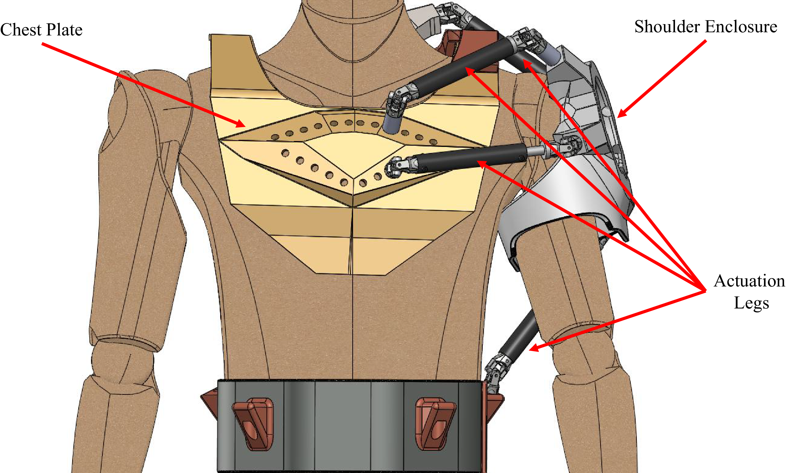
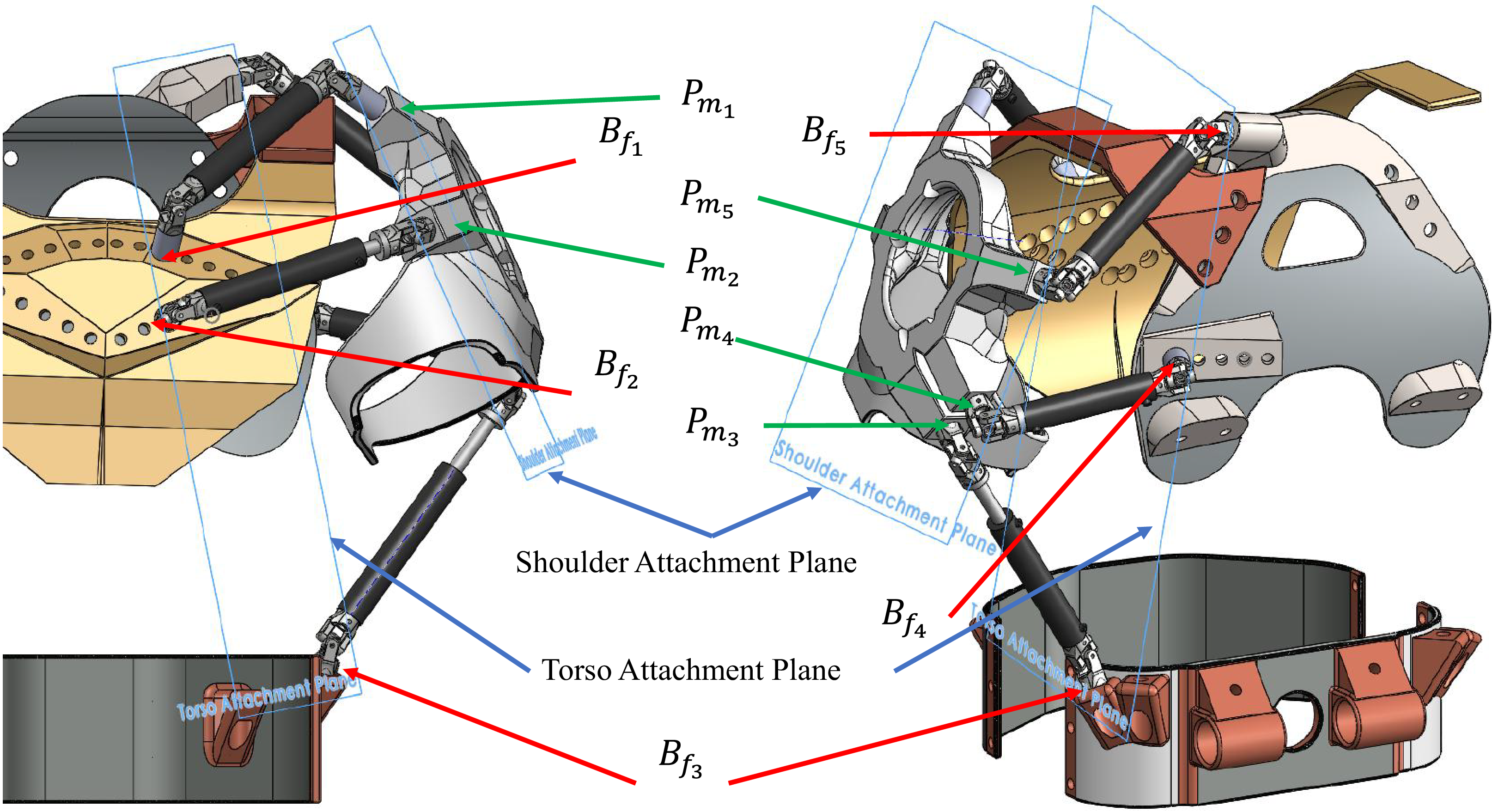
 Bfi
 Pmi
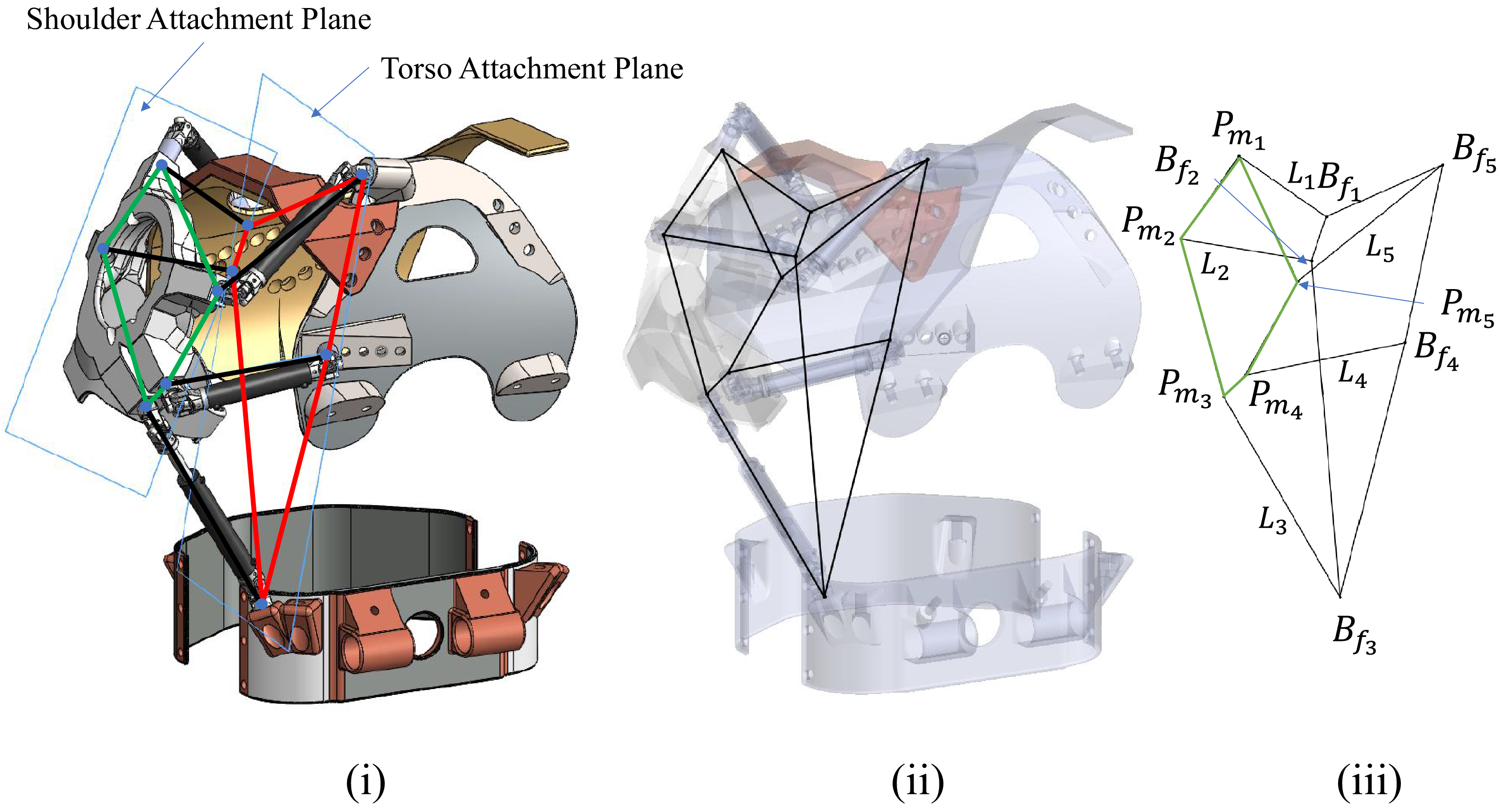
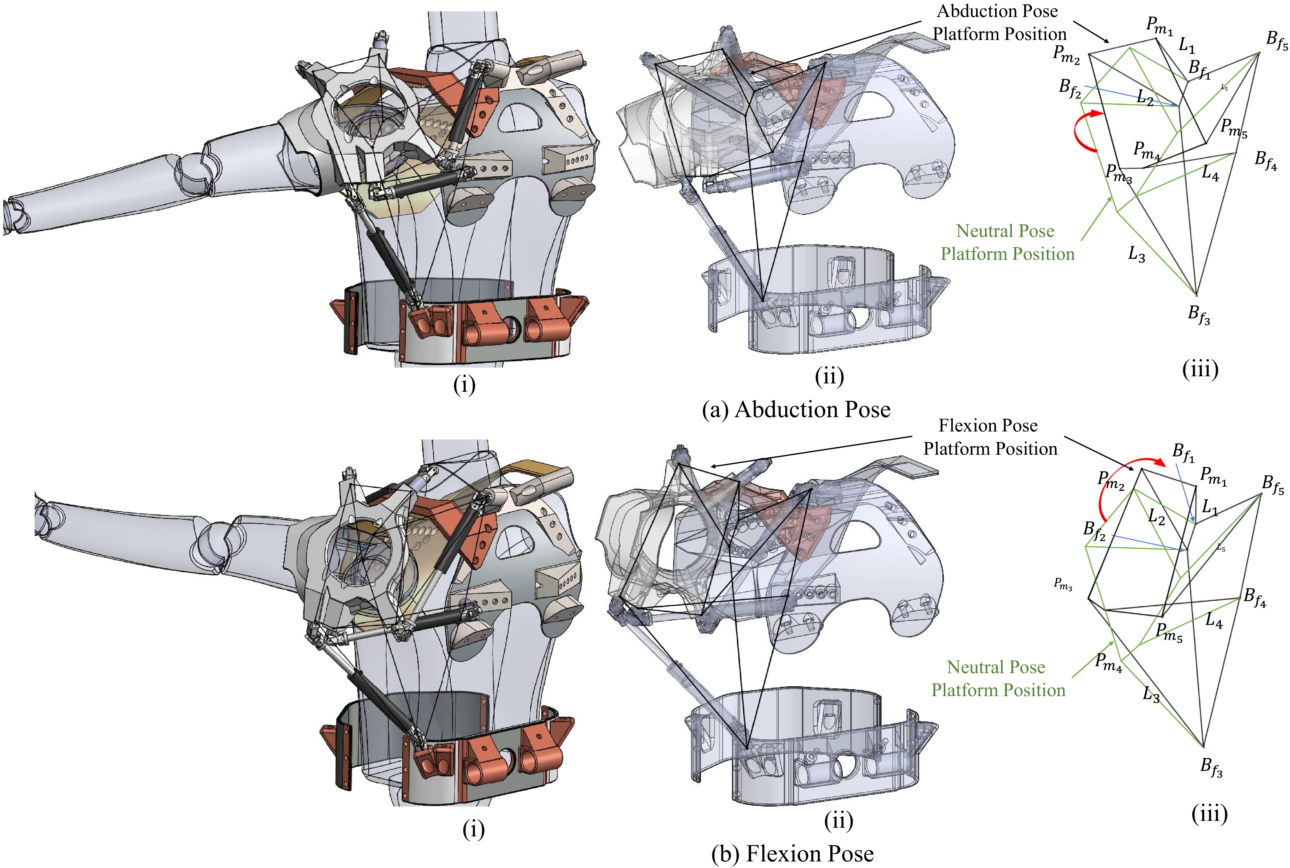
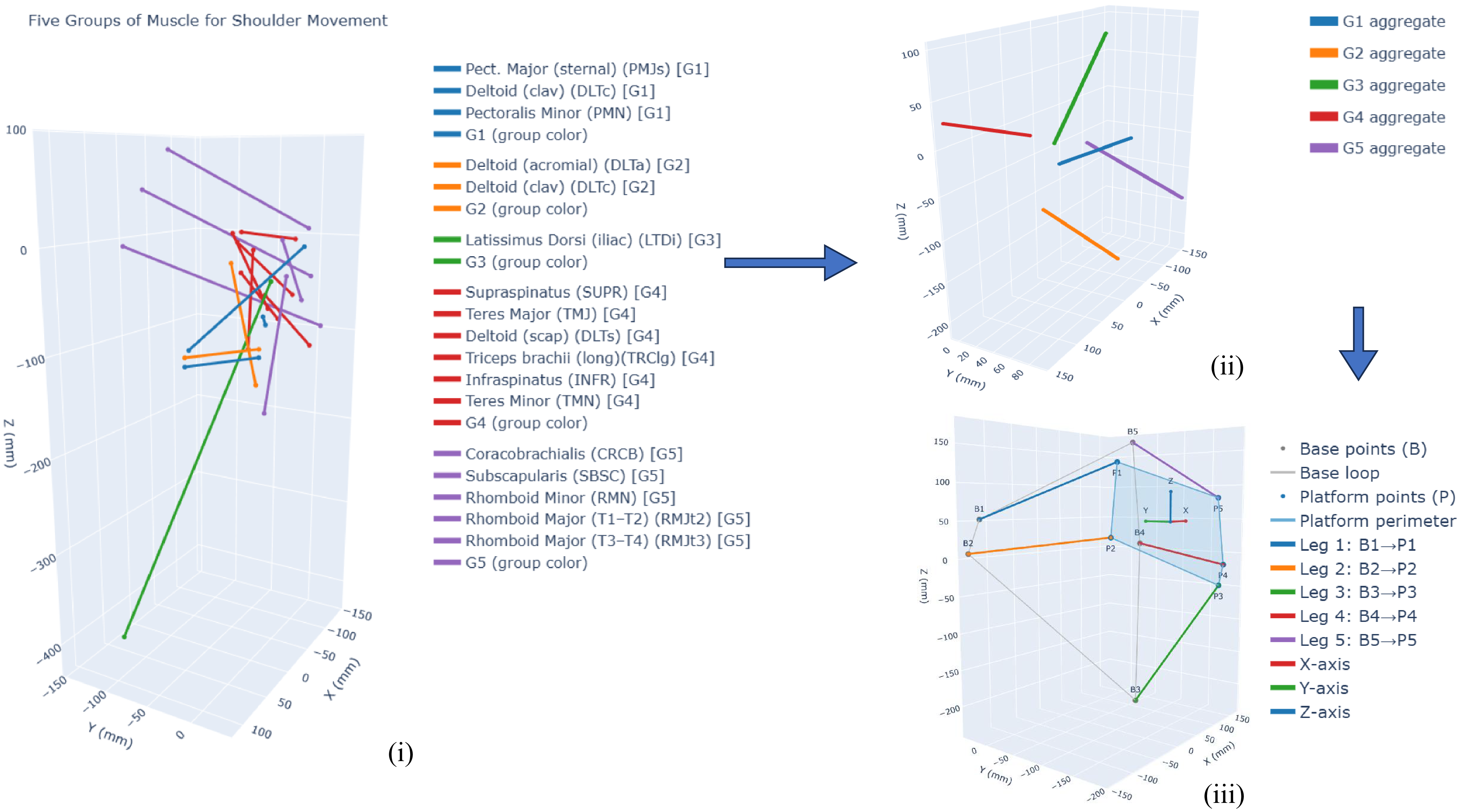
 B1..5
 P1..5
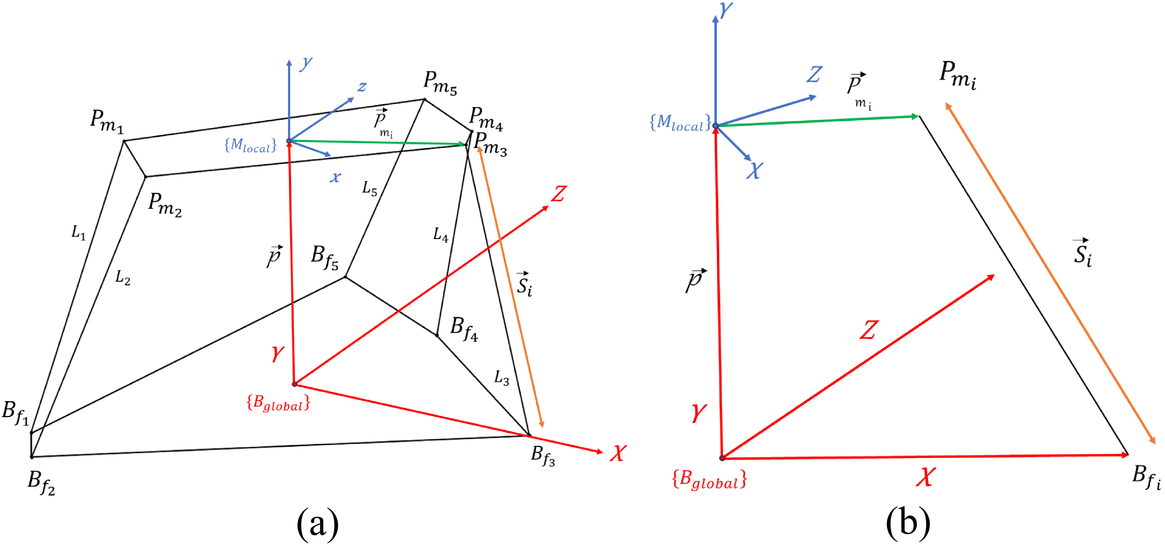
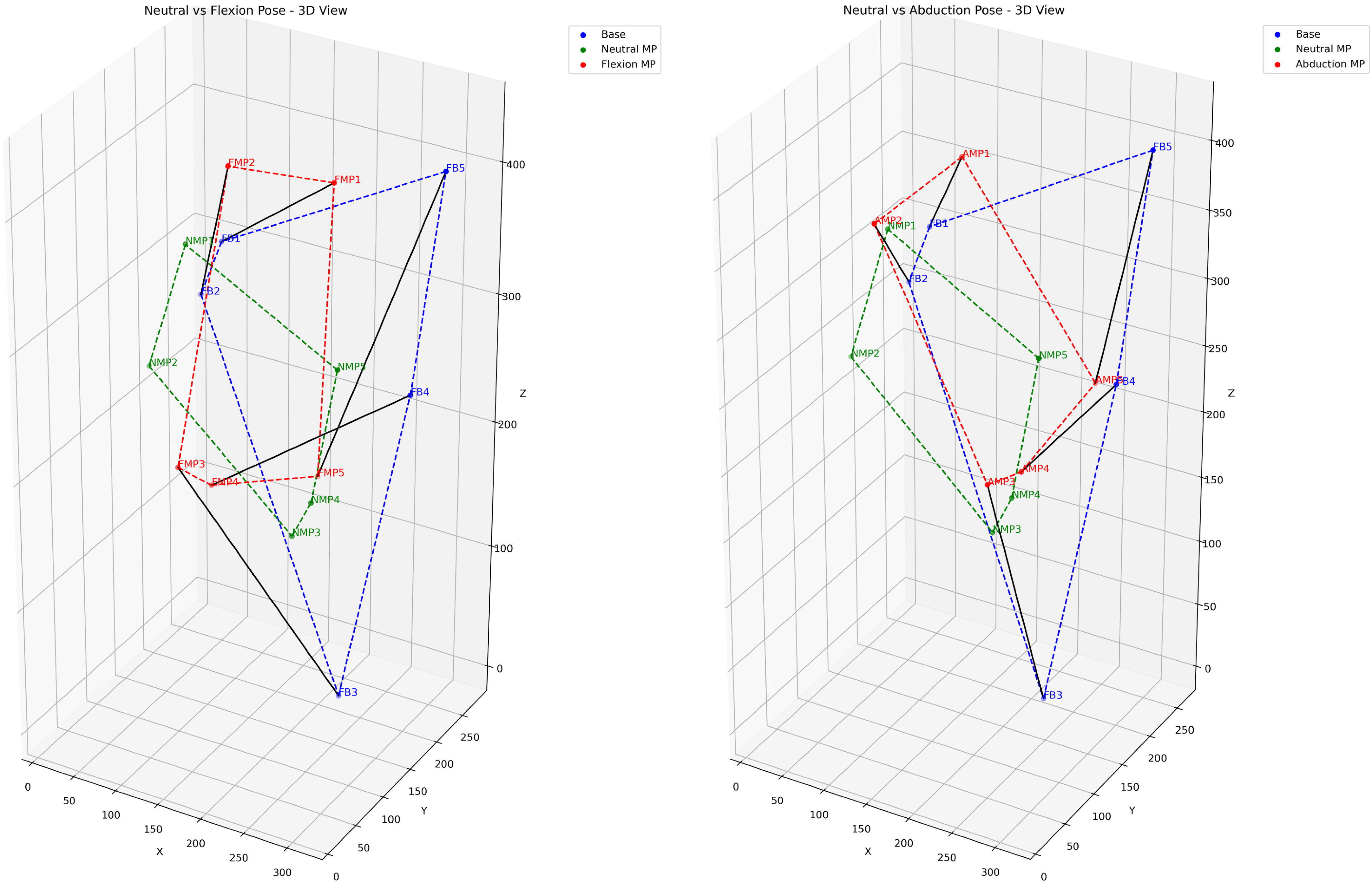
 Pmi
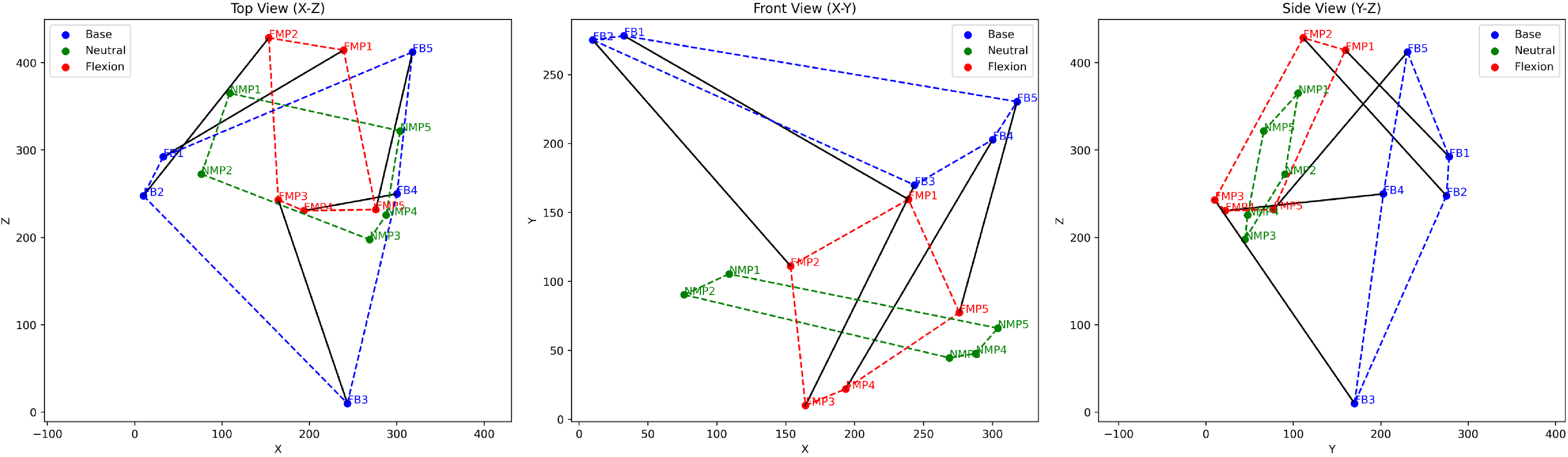
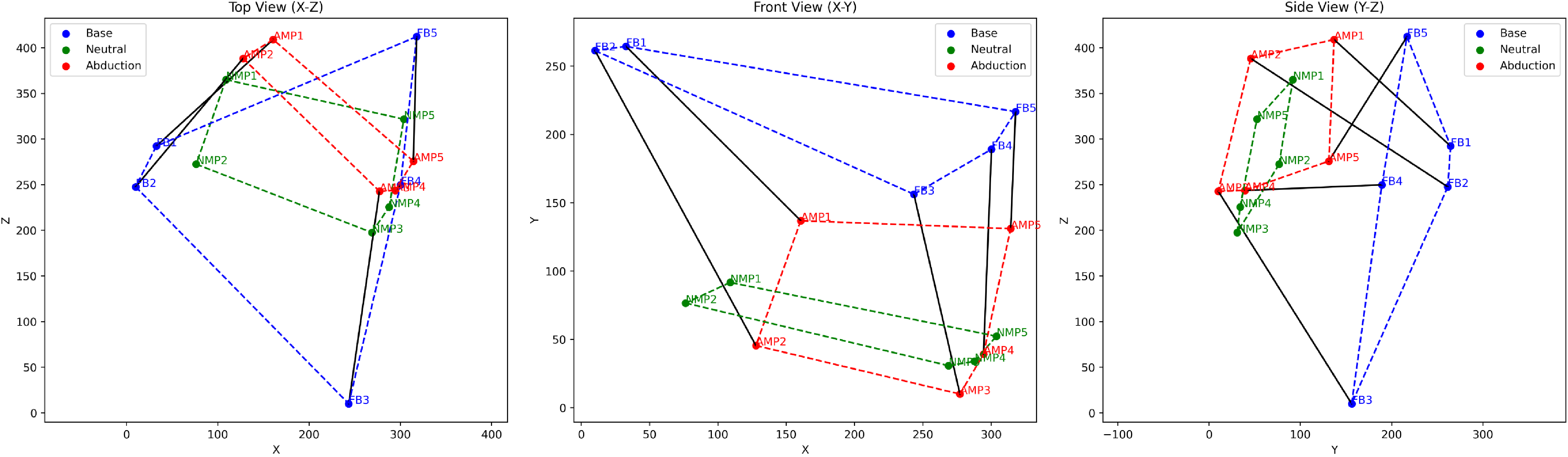
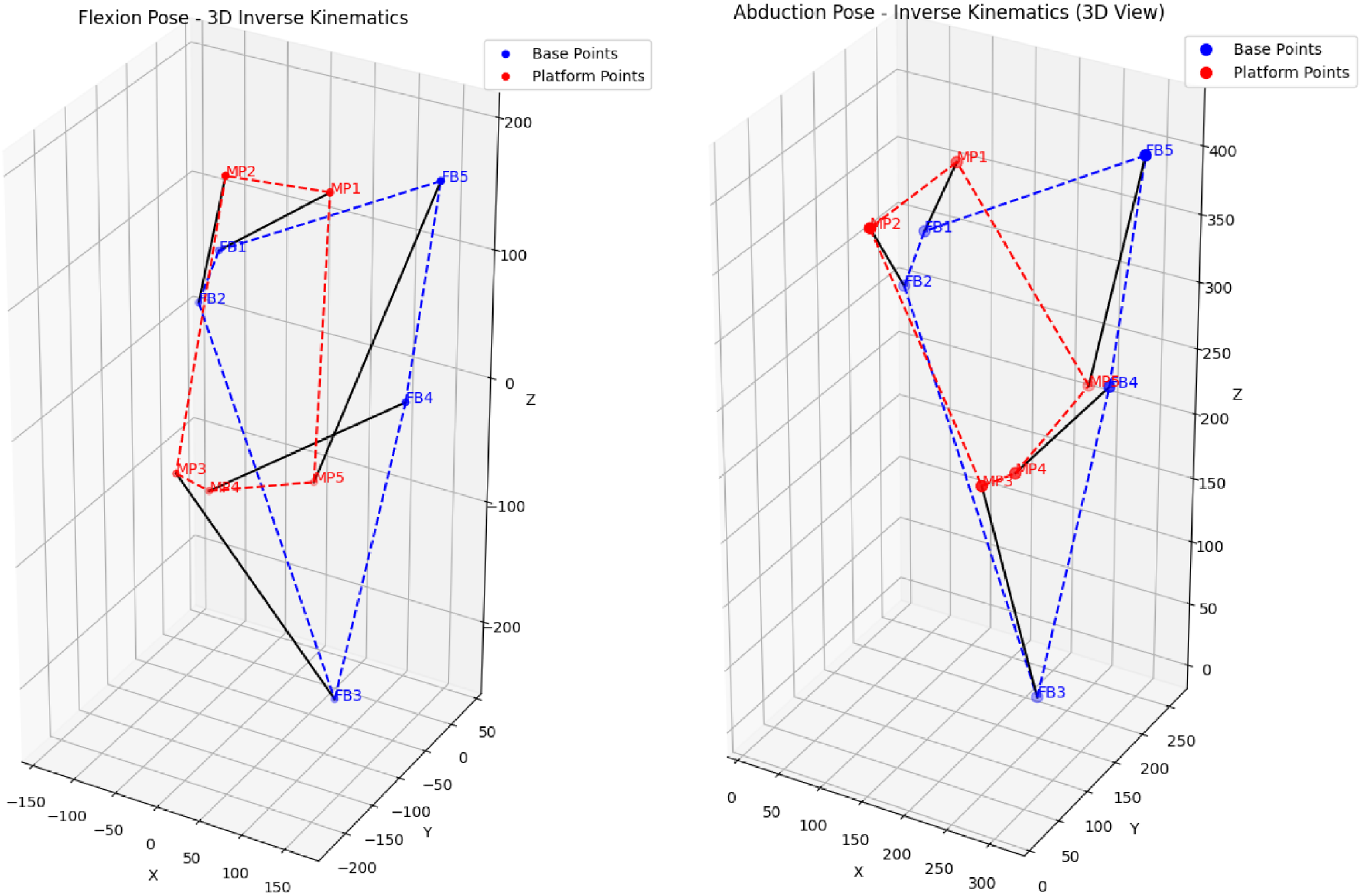
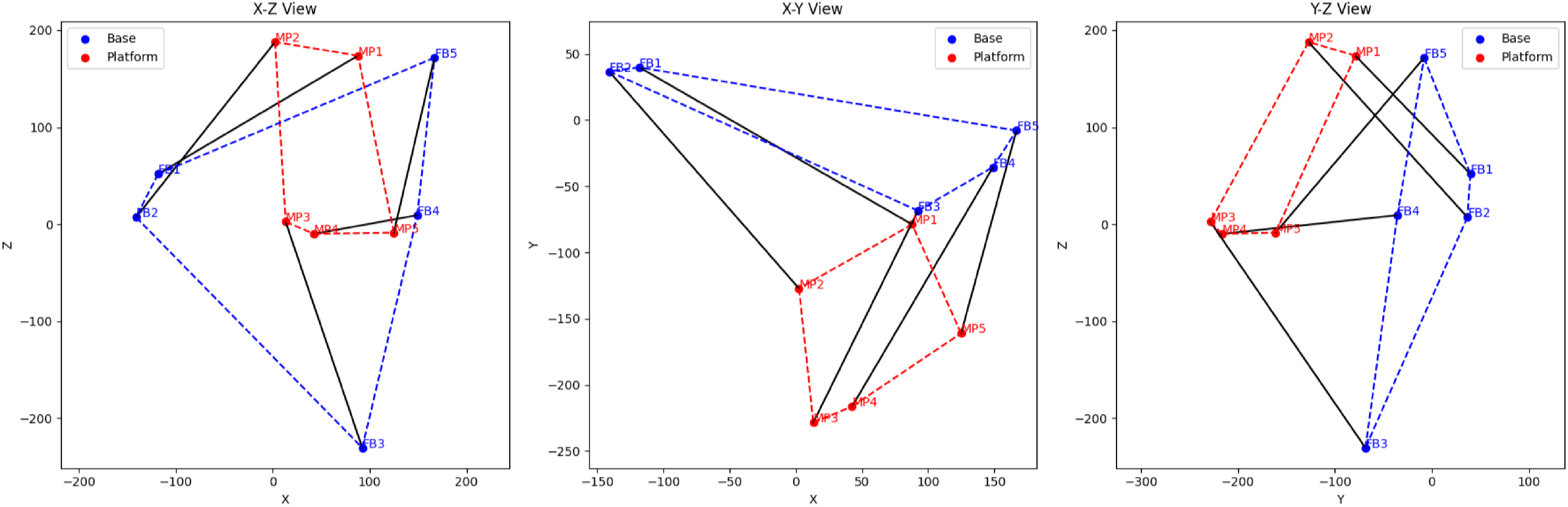
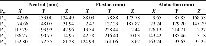
 Pmi
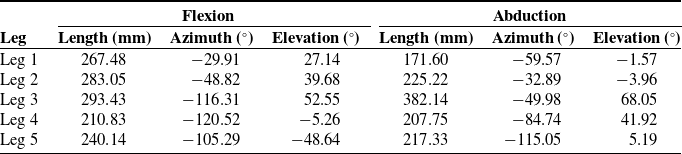
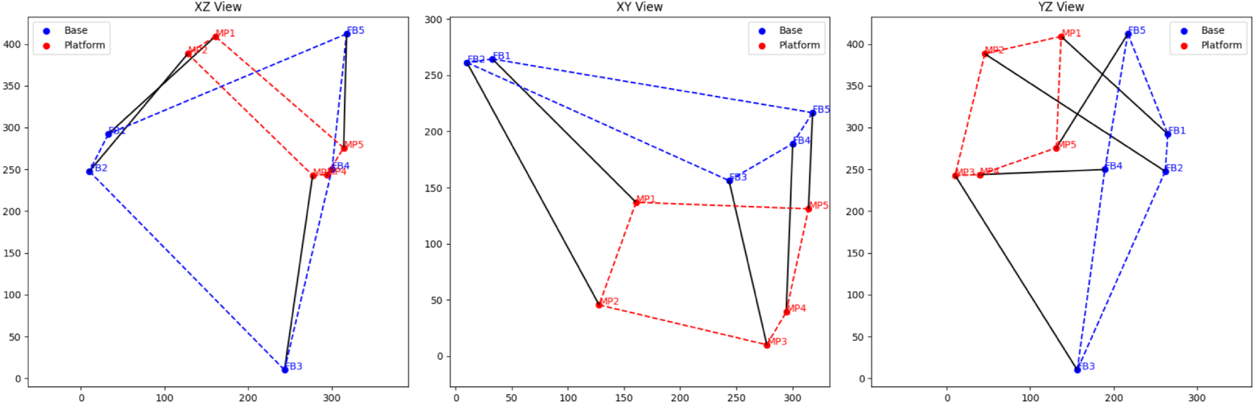

 σmin(J)<10−5
 κ(J)>104
 σmin(C)<10−5
 αres<10−5
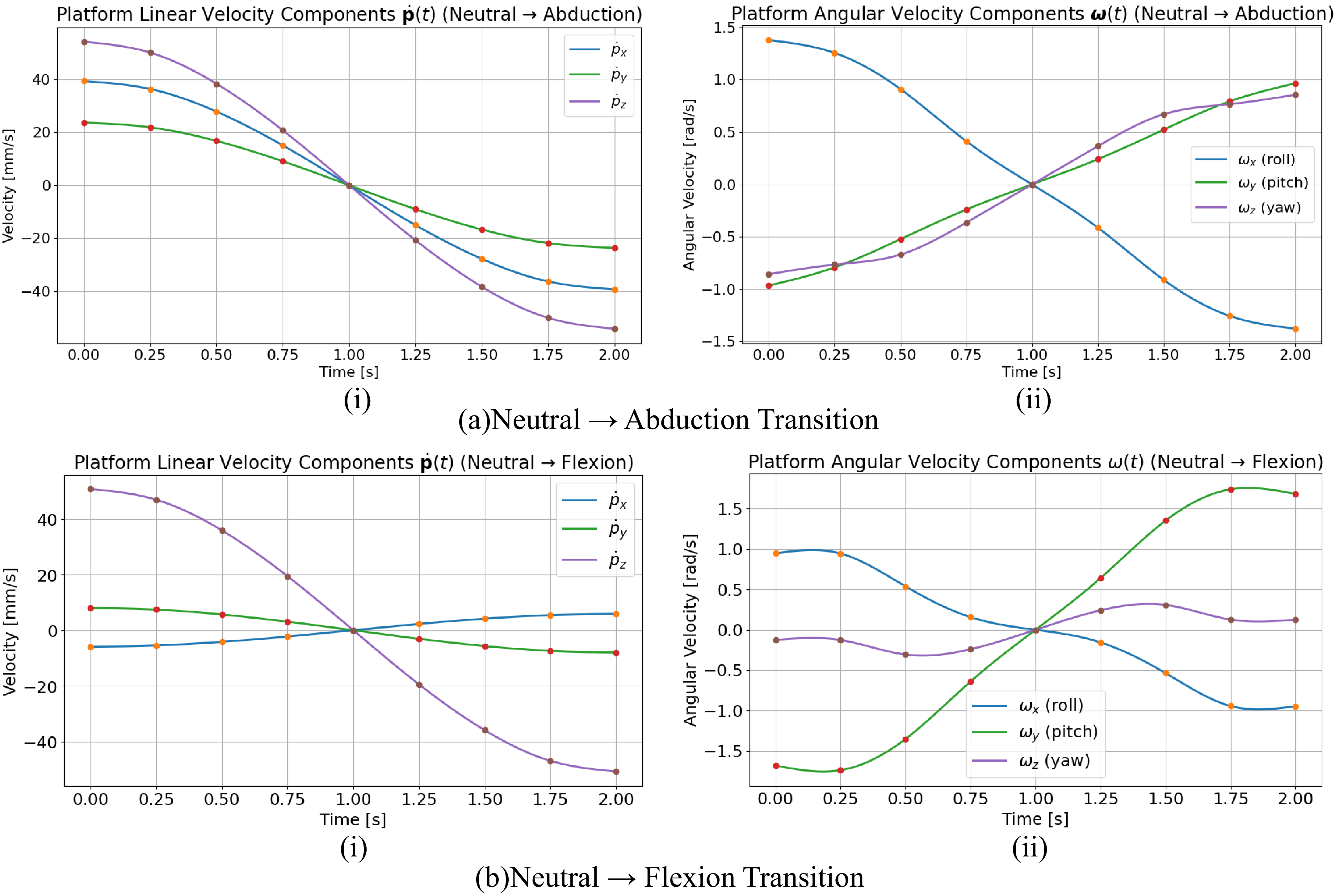
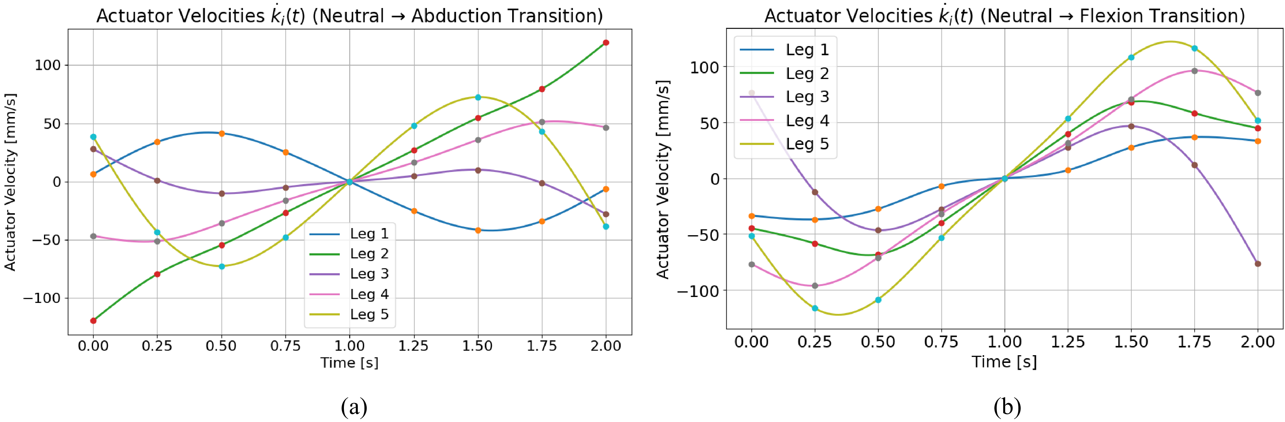
 k˙i(t)
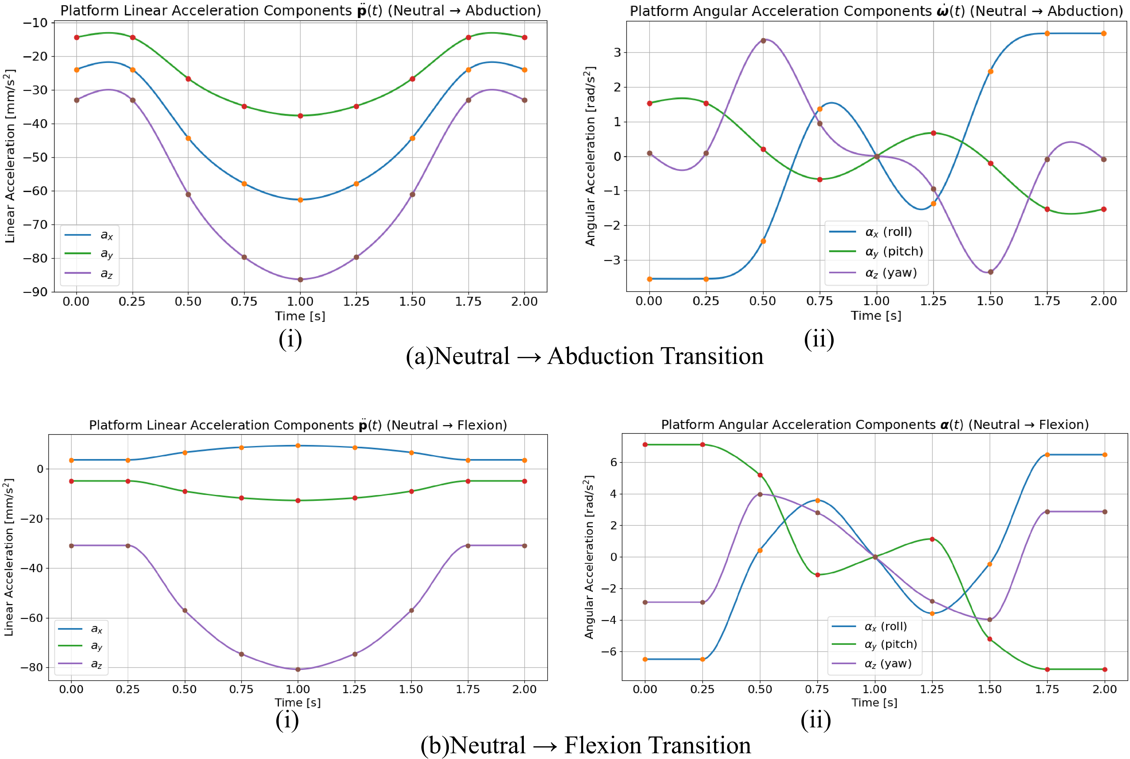
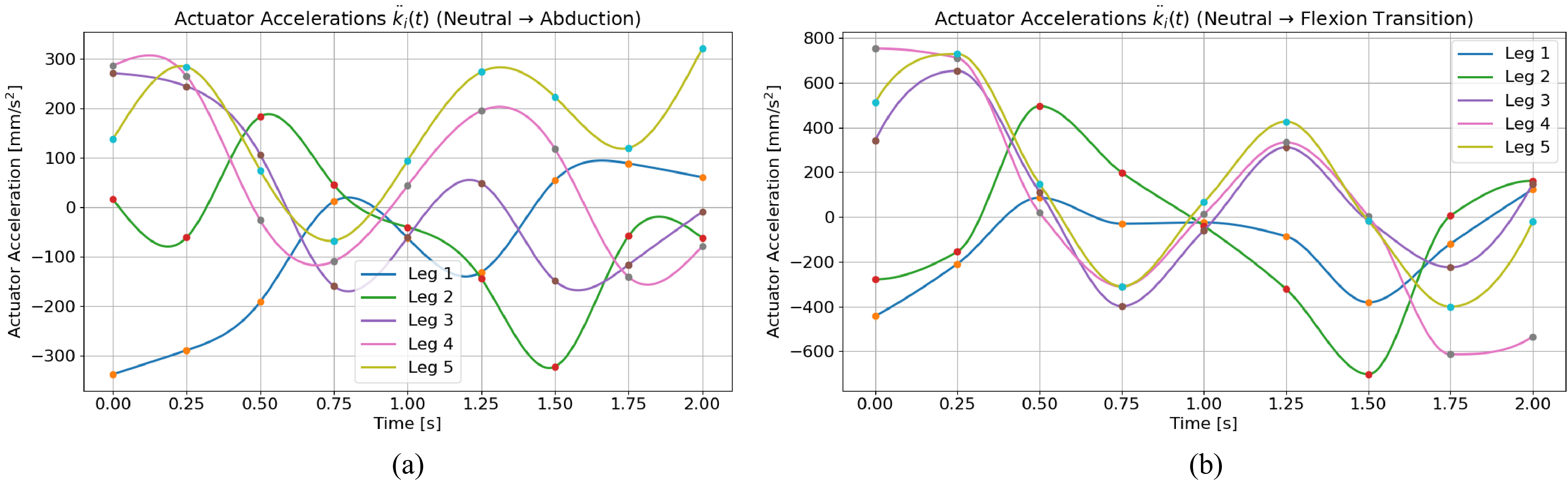
 k¨i(t)
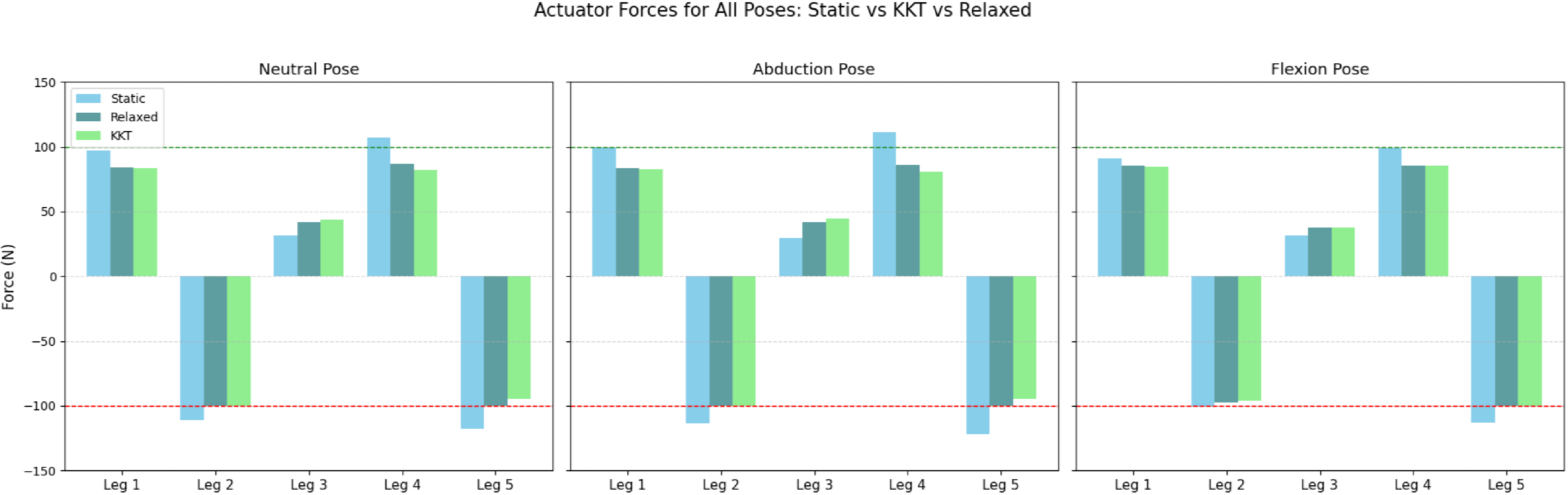
 ±