
Introduction
The profuse  $\left\{ {10\bar{1}2} \right\}$ deformation twinning [Reference El Kadiri, Barrett, Wang and Tomé1] and lack of active slip systems [Reference Yoo2] in common hexagonal close packed (HCP) Mg alloys lead to plastic anisotropy [Reference Mayama, Aizawa, Tadano and Kuroda3] and poor formability [Reference Chino, Kado and Mabuchi4], which limits the potential applications of Mg alloys as lightweight structural materials [Reference Hirsch and Al-Samman5]. For example, in deformation for pure Mg with a fiber texture, the compressive yield strength (CYS) is much lower than the tensile yield strength (TYS) due to profuse twinning at low stress during compression [Reference Mayama, Aizawa, Tadano and Kuroda3]. The ratio of CYS/TYS is referred to as yield asymmetry, which is not desirable in structural materials as the materials often undergo both tension and compression loads. One effective approach researchers have taken to suppress twinning and/or enhance homogeneous deformation in Mg alloys is reducing grain size [Reference Barnett, Keshavarz, Beer and Atwell6, Reference Ghaderi and Barnett7, Reference Panigrahi, Kumar, Kumar, Yuan, Mishra, DeLorme, Davis, Howell and Cho8, Reference Lee, Chou, Hsiao, Chang, Chang and Kao9, Reference Choi, Kim, Shin and Bae10, Reference Suhuddin, Mironov, Sato, Kokawa and Lee11, Reference Mishra and Ma12]. On the one hand, it is a general trend for twinning to be suppressed as grain size decreases; on the other hand, however, it appears that different alloy systems exhibit different degrees of suppression, with decreasing grain sizes [Reference Panigrahi, Kumar, Kumar, Yuan, Mishra, DeLorme, Davis, Howell and Cho8]. For example, a rare-earth containing WE43 alloy exhibits slip dominant deformation and a CYS/TYS value of 0.96 at a critical grain size of ∼2.2 μm [Reference Panigrahi, Kumar, Kumar, Yuan, Mishra, DeLorme, Davis, Howell and Cho8]. Therefore, alloying elements, especially rare earth elements, also play an important role in suppressing twinning and enhancing homogeneous deformation in Mg alloys [Reference Ghaderi and Barnett7, Reference Sandlöbes, Zaefferer, Schestakow, Yi and Gonzalez-Martinez13, Reference Sandlöbes, Pei, Friák, Zhu, Wang, Zaefferer, Raabe and Neugebauer14, Reference Stanford, Marceau and Barnett15, Reference Stanford, Cottam, Davis and Robson16]. Among the rare earth elements, alloying element Y has recently received particular attention [Reference Sandlöbes, Zaefferer, Schestakow, Yi and Gonzalez-Martinez13, Reference Stanford, Marceau and Barnett15, Reference Stanford, Cottam, Davis and Robson16, Reference Tang, Liu, Ding, Zhang, Zhao, Lavernia and Zhu17, Reference Zhang, Jiang, Schoenung, Mahajan and Lavernia18, Reference Yasi, Hector and Trinkle19, Reference Yasi, Hector and Trinkle20] due to its possible effects of strengthening basal slip [Reference Yasi, Hector and Trinkle20], enhancing nonbasal slip [Reference Sandlöbes, Zaefferer, Schestakow, Yi and Gonzalez-Martinez13, Reference Yasi, Hector and Trinkle19] and suppressing twinning [Reference Stanford, Marceau and Barnett15, Reference Stanford, Cottam, Davis and Robson16].
In our previous study [Reference Zhang, Wen, Kumar, Chen, Zhang, Beyerlein, Schoenung, Mahajan and Lavernia21], we reported virtual yield symmetry and significantly reduced strength differential [Reference Mayama, Aizawa, Tadano and Kuroda3] in a fine-grained Mg 2.5 at.% Y alloy (FG Mg–2.5Y). These unusual properties are mainly attributable to the ultrafine grain size (∼1 μm), modified texture, and the alloying effect of Y in suppressing twinning and enhancing nonbasal slip. However, it is difficult to differentiate the intrinsic alloying effect from the extrinsic effects (grain size, texture, etc.) even if the former were to play a more important role than the latter. A survey of the current literature reveals that micro/nano-pillar deformation experiments are particularly informative [Reference Yu, Legros and Minor22, Reference Legros23, Reference Greer and De Hosson24, Reference Xie, Shrestha, Cao, Felfer, Wang, Liao, Cairney and Ringer25] for studying deformation twinning [Reference Yu, Qi, Chen, Mishra, Li and Minor26, Reference Ye, Mishra, Sachdev and Minor27, Reference Liu, Wang, Li, Lu, Zhang, Shan, Li, Jia, Sun and Ma28, Reference Kim, Yi, Huang and Lilleodden29], dislocation/slip activity [Reference Yu, Qi, Chen, Mishra, Li and Minor26, Reference Ye, Mishra, Sachdev and Minor27, Reference Lilleodden30, Reference Byer, Li, Cao and Ramesh31, Reference Aitken, Fan, El-Awady and Greer32, Reference Zhou, Beyerlein and LeSar33, Reference Zhou, Biner and LeSar34], plastic anisotropy [Reference Yu, Qi, Mishra, Li and Minor35], and the alloying effect [Reference Ye, Mishra, Sachdev and Minor27, Reference Aitken, Fan, El-Awady and Greer32, Reference Wang and Stanford36], in Mg and Mg alloys. Therefore, as a follow up to our previous study on the bulk FG Mg–2.5Y alloy, in situ transmission electron microscopy (in situ TEM) mechanical testing is employed, for the first time, to systematically investigate deformation behavior of Mg–Y nano-pillars, in an attempt to further understand the alloying effect.
Results
Based on the electron back-scattered diffraction (EBSD) data for target grains, Schmid factors for each possible deformation mode, i.e., slip (basal, prismatic, or pyramidal) and twinning ( $\left\{ {10\bar{1}2} \right\}$ type), were calculated for each grain. Therefore, the dominant deformation mode in each Mg–Y pillar machined from the target grains was also inferred. The pillars could be divided into three groups: (i) Pillars oriented for basal slip dominated deformation, referred to as X-type pillars (analogous to X-type grains in [Reference Zhang, Wen, Kumar, Chen, Zhang, Beyerlein, Schoenung, Mahajan and Lavernia21]). (ii) Pillars oriented for prismatic slip or twinning dominated deformation, referred to as Y-type pillars (analogous to Y-type grains in [Reference Zhang, Wen, Kumar, Chen, Zhang, Beyerlein, Schoenung, Mahajan and Lavernia21]). (iii) Pillars oriented for compression, approximately along c-axis (Pillar Z), which serve as a rare case.
Basal slip for X-type pillars
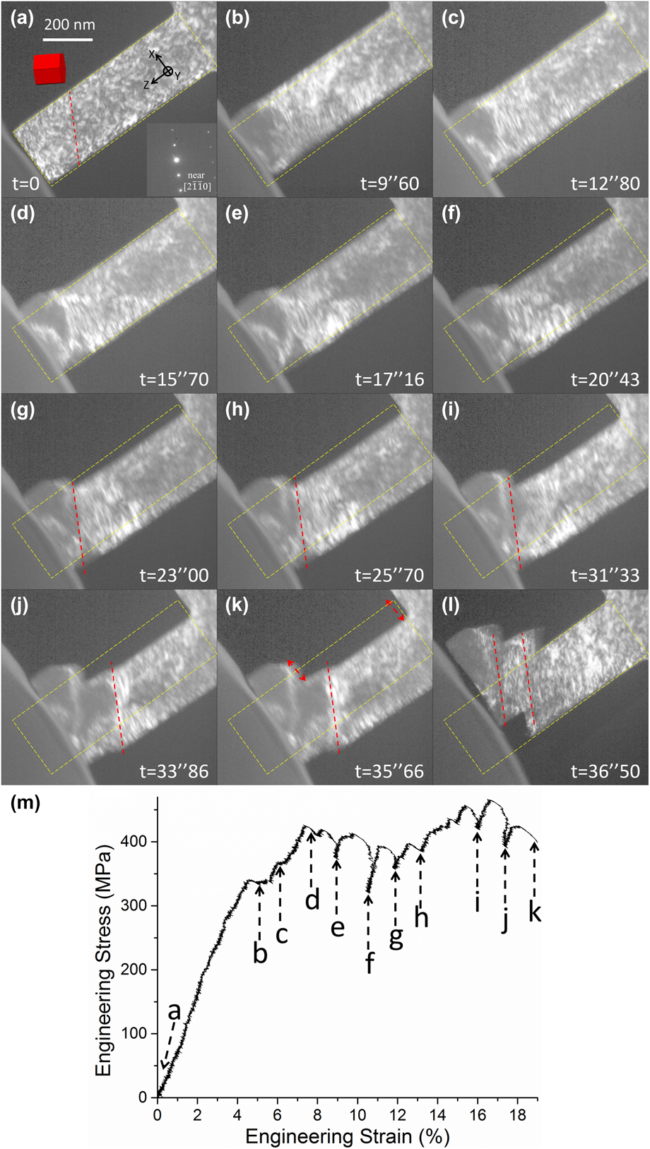
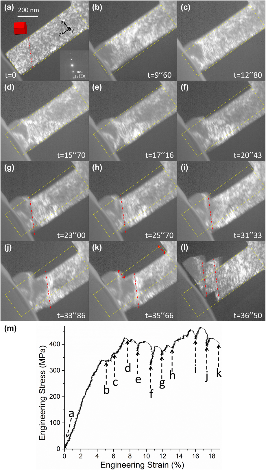
Figure 1 shows snapshots of the in situ deformation process [Figs. 2(a)–2(l)] and the corresponding engineering stress–strain curve [Fig. 2(m)] of one Mg–Y nano-pillar (Pillar X1, see also Supplementary material Video #1). Particularly in Fig. 2(a), EBSD data and electron diffraction patterns obtained in TEM prior to deformation were combined to determine the crystallographic orientation of the pillar. Therefore for Pillar X1, the angle between the c-axis and loading direction (i.e., φ angle in [Reference Zhang, Wen, Kumar, Chen, Zhang, Beyerlein, Schoenung, Mahajan and Lavernia21]) was ∼42°, meaning the pillar would most likely be deformed by basal slip. The approximate trace of the basal plane was highlighted by the red dashed line in Fig. 2(a). Following the schematics in Fig. 2, the yellow dashed box marks the initial position and shape of Pillar X1.
(a)–(l) In situ deformation process of Pillar X1. (m) Corresponding engineering stress–strain curve for Pillar X1.
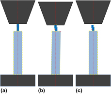
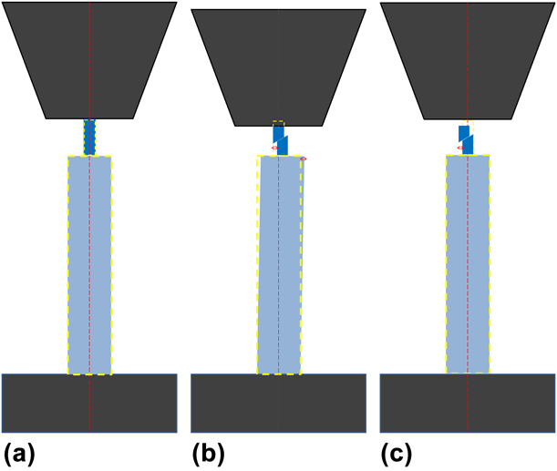
Schematic illustration of the “pillar-on-pillar” design. (a) The dark blue nano-pillar sits on the light blue micro-pillar, with the black indenter on top and the base bulk material at the bottom (also dark). The small and large yellow dashed boxes mark the initial positions of the nano- and micro-pillars, respectively, whereas the red dashed line represents the loading axis. (b) As indentation progresses and shear event occurs (see the red arrow beside the nano-pillar), the top of the nano-pillar remains attached to the indenter due to LS. Meanwhile, the bottom of the nano-pillar is able to move to the right due to the slightly elastic “wiggling” of the micro-pillar (see the red arrow beside the micro-pillar), thus compensating the lateral movement necessitated by the shear. (c) After the shear event and the unloading of the indenter, the micro-pillar elastically wiggles back to its initial position (i.e., large yellow dashed box), enabling the bottom part of the nano-pillar to also return to its initial position (i.e., small yellow dashed box), whereas the top part has been sheared to the left (see the red arrow).
The prominent advantage of in situ TEM deformation is that each snapshot corresponds to an actual point in the stress–strain curve. For example, around point b and c, there were two minor “jumps” in the curve; they actually corresponded to localized deformation at the top corner of Pillar X1 during initial stage of deformation, as can be seen in Figs. 2(b) and 2(c), respectively. However, deformation of the entire pillar did not occur until around point d/Fig. 2(d), where a yield drop (or a minimal “strain burst” [Reference Jennings, Burek and Greer37]) probably occurred due to shear deformation. Therefore, the yield stress in this study was defined as the stress upon which the first yield drop occurred due to shear deformation of the entire pillar. As deformation progressed, the trace of shear deformation that likely corresponded with basal slip became more visible [see Figs. 2(g)–2(i)]. It was also noted that a new “shear zone” gradually developed [Figs. 2(j) and 2(k)] away from the top of Pillar X1. Eventually it was the sudden large shear in the new zone that led to the failure of Pillar X1 [Fig. 2(l)]. Referring to the yellow dashed box in (k), one can see that due to shear, the “top” of Pillar X1 was displaced relatively to the top-left, whereas the “bottom” was displaced correspondingly to the bottom-right (see the red arrows): thanks to the lateral wiggling of the micro-pillar underneath. In the meantime, one can also see the length of Pillar X1 was significantly reduced as compared to its initial shape [Fig. 1(k)], confirming the dominant uniaxial deformation. After failure, it was confirmed that the shear deformation in both shear zones indeed occurred in the basal plane, as the traces of the two zones [highlighted by two red dashed lines in Fig. 2(l)] were nominally parallel with that of basal plane. In addition, while the nano-pillar X1 experienced severe shear deformation, the micro-pillar underneath elastically recovered, returning the bottom part of X1 exactly to its initial position outlined by the yellow dashed box in Fig. 2(l). The yield stress of Pillar X1 was measured to be ∼425 MPa, and the critical resolved shear stress for basal slip (CRSSBasal hereafter) was calculated to be ∼200 MPa.
In addition to Pillar X1, two more single-crystal Mg–Y pillars X2 and X3 were also quantitatively tested, and the yield stresses were determined in the same manner. Table I summarizes the data for X-type pillars. In the table, SF means Schmid factor; 〈c + a〉-I and 〈c + a〉-II mean slip in pyramidal-I plane and pyramidal-II plane, respectively. It is noted that in each pillar, the Schmid factor for basal slip was always the highest among all deformation modes. In addition, the slip trace analysis reveals that basal slip was indeed the dominant deformation mode in these pillars. Therefore, the average CRSSBasal value based on yield stresses for the three pillars was calculated to be ∼210 ± 20 MPa.
Summary for X-type pillars.

Prismatic slip for Y-type pillars
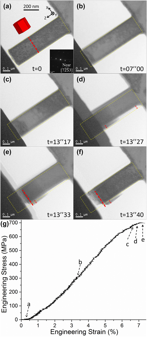
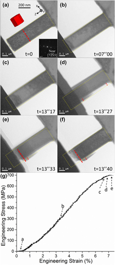
Similar to X-type pillars, the orientations of Y-type pillars were determined based on EBSD data for the corresponding target grains and electron diffraction in TEM. Figure 3 (see also Supplementary material Video #2) shows an example of a Y-type pillar Y1. Pillar Y1 was oriented for compression perpendicular to c-axis [Fig. 3(a)], which would favor either prismatic slip or  $\left\{ {10\bar{1}2} \right\}$ deformation twinning [Reference Partridge38]. The red dashed line in Fig. 3(a) highlighted the trace of prismatic planes. As deformation progressed [Figs. 3(b) and 3(c)], shear deformation immediately occurred [Figs. 3(d) and 3(e)] after yield [Fig. 3(c)]. By referring to the yellow dashed box and the red arrows in Fig. 3(d), one can see the subtle lateral displacement of Pillar Y1, namely, the “top” of Y1 was displaced slightly to the bottom-right, whereas the “bottom” of Y1 was displaced accordingly to the top-left: thanks again to the wiggling of the micro-pillar underneath. Close examination of the pillar after unloading in Fig. 3(f) revealed that a slip trace (red dashed line) matched accurately with the trace of prismatic planes, as highlighted in Fig. 3(a). Therefore, it was confirmed that Pillar Y1 was deformed by prismatic slip. In addition, one can also notice that after unloading [Fig. 3(f)], the bottom part of Y1 returned to its initial position due to elastic recovery of the micro-pillar underneath; meanwhile, the top part of Y1 was displaced slightly to the bottom-right, whereas the length of Y1 was significantly reduced due to the dominant uniaxial stress. The yield stress of Pillar Y1 was measured to be ∼665 MPa, and the CRSS for prismatic slip (CRSSprism hereafter) was calculated to be ∼290 MPa.
(a)–(f) In situ deformation process of Pillar Y1. (g) Corresponding engineering stress–strain curve for Pillar Y1.
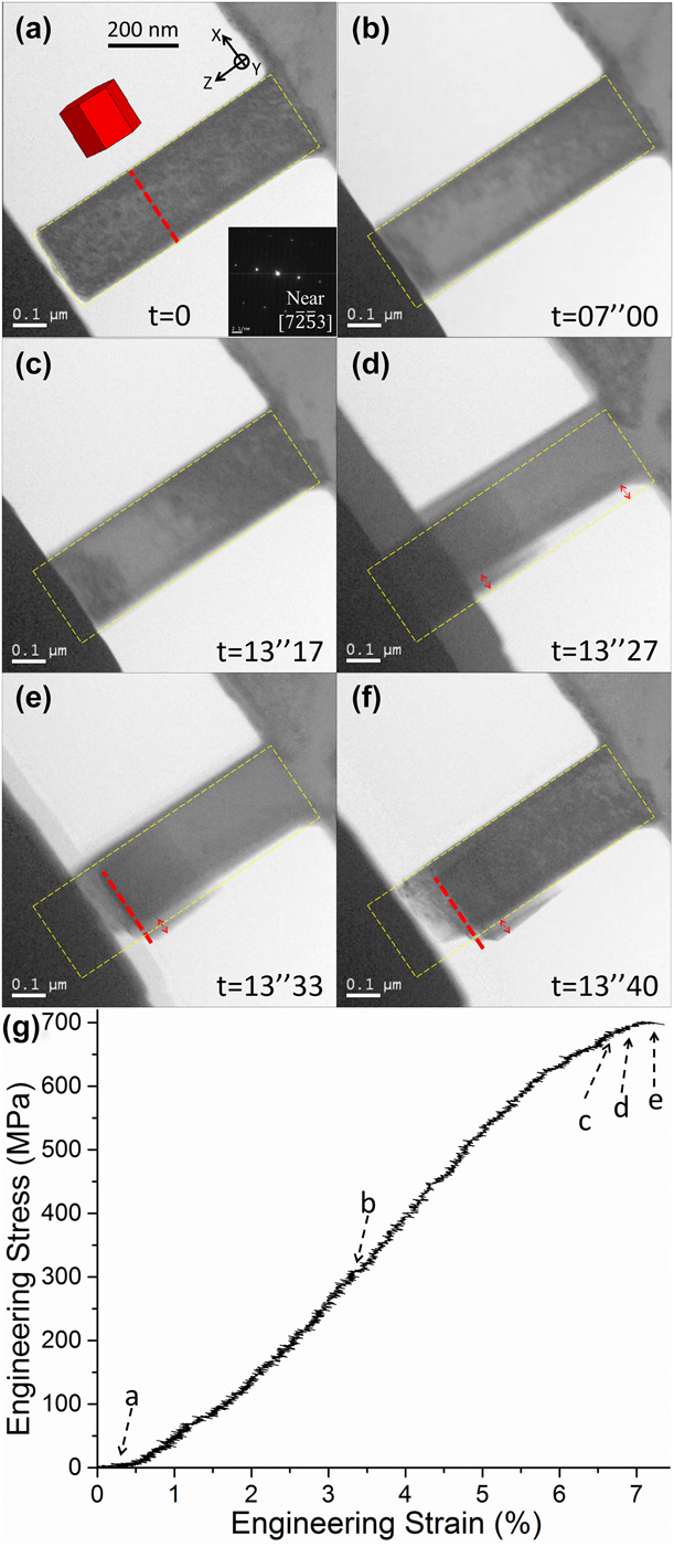
In addition to Pillar Y1, two more single-crystal Mg–Y pillars Y2 and Y3 were also quantitatively tested, and the yield stresses were determined in the same manner. Following Tables I and II summarizes the data for Y-type pillars. The average CRSSprism value based on yield stresses for the three pillars was calculated to be ∼280 ± 10 MPa. Three aspects are worth noting: (i) Even though the Schmid factor for  $\left\{ {10\bar{1}2} \right\}$ twinning was comparable to that for prismatic slip, twinning was not observed in any Y-type pillars. (ii) The Schmid factor for basal slip was always the lowest for each Y-type pillar. Considering that the average CRSSBasal value was ∼210 MPa obtained from X-type pillars, basal slip could not have been active in the Y-type pillars as the required stress for that would have been much higher than the yield stress in each Y-type pillar. (iii). However, the Schmid factor for pyramidal slip is similar to, or sometimes even higher than, that for prismatic slip. Considering that both CRSSprism and CRSSPyram (meaning CRSS for pyramidal slip) would generally be much higher than CRSSBasal in Mg or Mg alloys [Reference Yu, Qi, Mishra, Li and Minor35, Reference Partridge38, Reference Koike, Kobayashi, Mukai, Watanabe, Suzuki, Maruyama and Higashi39], it is acknowledged that pyramidal slip was not completely ruled out in the Y-type pillars, unless deformation of pillars predominantly by pyramidal slip are investigated, e.g., c-axis compression [Reference Lilleodden30, Reference Byer, Li, Cao and Ramesh31, Reference Aitken, Fan, El-Awady and Greer32, Reference Byer and Ramesh40].
Summary for Y-type pillars.

Rare case: Pillar Z oriented for c-axis compression
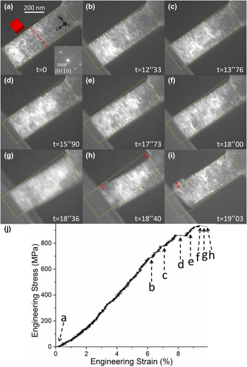
In the case of a bulk material with weak basal texture [Reference Zhang, Wen, Kumar, Chen, Zhang, Beyerlein, Schoenung, Mahajan and Lavernia21], statistically, it is easy to locate X-type target grains (i.e., with their c-axis inclined relative to the Z direction/in situ compression direction), relatively more difficult to find Y-type grains (i.e., c-axis perpendicular to the Z direction); and most difficult to identify a grain with its c-axis parallel to the Z direction. Therefore, only one such grain (Grain Z hereafter) was located herein, and only one pillar (Pillar Z) was machined from Grain Z, as shown in Fig. 4 (see also Supplementary material Video #3). Similar to previously mentioned pillars, the initial localized deformation at the pillar corner [Figs. 4(b) and 4(c)] led to minimal jumps in the stress–strain curve [point b and c in Fig. 4(j)], whereas yield of the entire pillar occurs around point d. Subsequent deformation led to sudden shear/failure of the pillar [Figs. 4(e)–4(h)]. In Fig. 4(h), referring to the red arrows, one can see the top of Pillar Z was displaced relatively to top-left, whereas the bottom of Z was displaced correspondingly to bottom-right. In addition, referring to the yellow dashed box in Figs. 4(h) and 4(j), respectively, one can also see the significantly reduced pillar length due to dominant uniaxial deformation. Nevertheless, unlike Pillar X1 or Y1, clear slip trace(s) could not be discerned in deformed Pillar Z, which was probably caused by multiple active slip systems considering there are 12 independent pyramidal slip systems in Mg [Reference Xie, Alam, Caffee and Hemker41].
(a)–(i) In situ deformation process of Pillar Z. (j) Corresponding engineering stress–strain curve for Pillar Z.
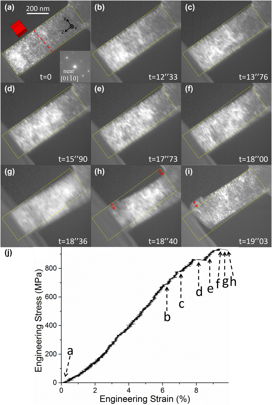
The mechanical data for Pillar Z were summarized in Table III. Since the yield stress was ∼860 MPa, considering the values of CRSSBasal (∼210 MPa) and CRSSprism (∼280 MPa), and the corresponding Schmid factors (0.15 and 0.01, respectively); it is unlikely that basal or prismatic slip was active in Pillar Z. Therefore, the dominant deformation mode must be pyramidal slip (i.e., 〈c + a〉 slip), and the corresponding CRSS value (CRSSPyram hereafter) was calculated to be ∼420 MPa.
Summary for pillar Z.

Discussion
Prismatic slip dominates deformation in Y-type Mg–Y pillars
The most striking result from the in situ TEM study herein was that prismatic slip dominated the deformation, whereas  $\left\{ {10\bar{1}2} \right\}$ twinning did not occur in Y-type pillars (namely, compression perpendicular to c-axis). In fact, the pillars could be deformed by prismatic slip up to any strain level (5%, 10%, 20%, etc.), even to failure. There was no sign of deformation twinning at any point of deformation. This finding was diametrically different from other micro/nano-pillar deformation study reported in the literature for single-crystal pillars of either pure Mg [Reference Ye, Mishra, Sachdev and Minor27, Reference Liu, Wang, Li, Lu, Zhang, Shan, Li, Jia, Sun and Ma28, Reference Kim, Yi, Huang and Lilleodden29, Reference Liu, Wan, Wang, Ma and Shan42] or Mg alloy [Reference Ye, Mishra, Sachdev and Minor27, Reference Wang and Stanford36], where twinning is always the dominant deformation mode under similar indentation conditions. For example, twinning was still the dominant deformation mode in Mg–Zn pillars strengthened by nano-spaced precipitates [Reference Wang and Stanford36]. This finding also confirmed the deformation mechanisms for the bulk FG Mg–2.5Y alloy previously reported [Reference Zhang, Wen, Kumar, Chen, Zhang, Beyerlein, Schoenung, Mahajan and Lavernia21], where it was revealed that Y-type grains (from which Y-type pillars were machined from) were deformed primarily by prismatic slip instead of twinning.
It is noted that in Y-type Mg–Y pillars, prismatic slip rather than twinning dominated deformation under ideal Schmid’s law governed deformation conditions. However, in polycrystalline deformation for bulk FG Mg–2.5Y, local stress fluctuation/concentration, especially at grain boundaries [Reference Beyerlein, McCabe and Tomé43, Reference Niezgoda, Kanjarla, Beyerlein and Tomé44], may still cause twinning to occasionally occur [Reference Zhang, Wen, Kumar, Chen, Zhang, Beyerlein, Schoenung, Mahajan and Lavernia21, Reference Zhang, Zheng, Zhou, Mahajan and Lavernia45]. Similarly, recent studies on the effect of rare-earth alloying elements (including Y) in suppressing twinning based on polycrystalline deformation [Reference Sandlöbes, Zaefferer, Schestakow, Yi and Gonzalez-Martinez13, Reference Sandlöbes, Pei, Friák, Zhu, Wang, Zaefferer, Raabe and Neugebauer14, Reference Stanford, Marceau and Barnett15, Reference Stanford, Cottam, Davis and Robson16] revealed that, on the one hand, twinning was indeed more or less suppressed, whereas nonbasal slip was enhanced [Reference Sandlöbes, Zaefferer, Schestakow, Yi and Gonzalez-Martinez13, Reference Sandlöbes, Pei, Friák, Zhu, Wang, Zaefferer, Raabe and Neugebauer14], especially when compared with that in polycrystalline pure Mg. On the other hand, some twins could still be observed [Reference Sandlöbes, Zaefferer, Schestakow, Yi and Gonzalez-Martinez13, Reference Sandlöbes, Pei, Friák, Zhu, Wang, Zaefferer, Raabe and Neugebauer14, Reference Stanford, Marceau and Barnett15, Reference Stanford, Cottam, Davis and Robson16]. Therefore, the polycrystalline “environment,” besides the variations in grain size or texture, would complicate the deformation mechanisms in each grain. This, in turn, demonstrates that in situ deformation plays an essential role in investigating intrinsic alloying effect on deformation mechanisms.
Nevertheless, even though phenomenologically we observed a lack of twins in deformed polycrystalline bulk material Mg–Y, as well as confirmed the fact that prismatic slip rather than twinning dominated deformation by in situ TEM study, fundamental questions concerning twinning mechanism(s) remain to be addressed: Why are twins profuse in pure Mg? How does a twin nucleate? Why did prismatic slip replace twinning in Mg–Y? In fact, our ongoing study on fundamental twinning mechanism(s) in pure Mg suggests that 〈c〉/〈c + a〉 dislocations are probably required for twin nucleation. Therefore, according to in situ deformation data for Mg–Y, since CRSSPyram (∼420 MPa) was much higher than CRSSBasal (∼210 MPa) and CRSSprism (∼290 MPa), whereas CRSSprism is comparable to CRSSBasal, if prismatic slip and basal slip are active enough to accommodate deformation, there is no need to activate pyramidal slip/〈c + a〉 dislocations; thus, the preceding dislocation structure for twin to nucleate would not be available. Indeed, active 〈c + a〉 slip was not documented in deformed bulk FG Mg–2.5Y [Reference Zhang, Wen, Kumar, Chen, Zhang, Beyerlein, Schoenung, Mahajan and Lavernia21]. In addition, Jeong et al. recently reported elegant in situ TEM study on twinning and prismatic slip in pure Mg, suggesting a pile-up of localized prismatic 〈a〉 dislocations may act as a precursor for twin nucleation [Reference Jeong, Alfreider, Konetschnik, Kiener and Oh46]. Conversely, one may infer that if prismatic 〈a〉 dislocations were more mobilized by certain alloying elements (i.e., Y), prismatic slip would simply “keep going,” replacing twinning as the dominant deformation mode. Jeong et al. also investigated the rate dependency of prismatic slip and twinning in pure Mg pillars. They found out twin nucleated much earlier and faster at a higher strain rate (i.e., 10−2/s), whereas at a lower strain rate (i.e., 10−4/s), precursor prismatic slip lasts longer and twin had a “delayed” nucleation. In comparison, our in situ deformation was performed with a 2 nm/s indentation rate. It corresponded to a ∼2.5 × 10⁻³/s quasi-static strain rate, in an effort to mimic conventional mechanical test condition for bulk materials. For all Y-type pillars deformed under this strain rate, the deformation process was dominated by prismatic slip, without any sign of deformation twinning.
Reduced plastic anisotropy in Mg–Y
Based on in situ deformation data for Mg–Y pillars, another remarkable finding was that the plastic anisotropy A(D), defined as A(D) = CRSSnon-basal/CRSSBasal [Reference Yu, Qi, Mishra, Li and Minor35], was as low as ∼1.4 based on CRSSprism/CRSSBasal. This value was even lower than the theoretical lower bound value (∼2) in pure Mg, let alone being much lower than that for bulk Mg or Mg alloys (10–100) [Reference Yu, Qi, Mishra, Li and Minor35]. It is noted that this theoretical lower bound was calculated based on the generalized stacking fault energy curves for basal, prismatic, and pyramidal slip in pure Mg; therefore, the theoretical CRSS values for the three slip systems were calculated to be 1.30, 1.99, and 2.62 GPa [Reference Yu, Qi, Mishra, Li and Minor35]. Based on in situ deformation for different sizes of pure Mg samples, Yu et al. reported that [Reference Yu, Qi, Mishra, Li and Minor35] only as the sample size was reduced below a critical value of ∼100 nm, would the A(D) value approach the theoretical lower bound (∼2), whereas even for samples with sizes between 200 and 400 nm (where the size of Mg–Y pillars falls in), A(D) would remain large (values not specified [Reference Yu, Qi, Mishra, Li and Minor35]).
Nevertheless, although in situ deformation could quantify the CRSS values (Tables I–III) with reasonable accuracy, it was difficult to unveil the underlying atomistic mechanisms responsible for the reduced A(D) value (i.e., plastic anisotropy) via experiments. Therefore, atomic/subatomic modeling study on alloying effects may provide some insight into this issue. A systematic study by Yasi et al. had revealed that while solute atom Y significantly strengthens basal slip by both strong solute–dislocation interaction (i.e., geometrical effect) and chemical bonding [Reference Yasi, Hector and Trinkle20], the solute atom Y also enhances prismatic slip by producing stable prismatic screw dislocation cores and reducing the stress needed for cross-slip (i.e., from basal plane to prismatic plane) [Reference Yasi, Hector and Trinkle19]. Consequently, plastic anisotropy, as characterized by A(D) = CRSSprism/CRSSBasal, is indeed reduced. Unfortunately, this kind of systematic study on alloying effects is not available for pyramidal slip yet, so results may vary on whether the value of CRSSPyram/CRSSBasal is reduced or not [Reference Kim, Jeon, Kim and Lee47, Reference Pei, Zhu, Friak, Sandlobes, von Pezold, Sheng, Race, Zaefferer, Svendsen, Raabe and Neugebauer48].
Therefore, we carried out preliminary calculation for CRSS values for Mg–Y alloy(s) based on the DFT data reported by Pei et al. [Reference Pei, Zhu, Friak, Sandlobes, von Pezold, Sheng, Race, Zaefferer, Svendsen, Raabe and Neugebauer48], and the results are as following: CRSSBasal ∼1.86 GPa (based on Mg47Y supercell), CRSSprism ∼0.78 GPa (based on Mg55Y supercell), CRSSPyram ∼2.12 GPa (based on Mg47Y supercell). These calculated results qualitatively agree with our in situ deformation data in that the A(D) value is significantly reduced as compared to that in pure Mg: A(D) = 0.42 based on CRSSprism/CRSSBasal, and A(D) = 1.14 based on CRSSPyram/CRSSBasal. Therefore, it is suggested that the presence of Y alloying element in the Mg lattice not only suppresses twinning activity but also reduces significantly the intrinsic plastic anisotropy of Mg. Consequently, Mg–Y alloy(s) should exhibit more homogeneous deformation, as reported in a previous study [Reference Zhang, Wen, Kumar, Chen, Zhang, Beyerlein, Schoenung, Mahajan and Lavernia21] and recent literature [Reference Sandlöbes, Zaefferer, Schestakow, Yi and Gonzalez-Martinez13, Reference Stanford, Marceau and Barnett15, Reference Stanford, Cottam, Davis and Robson16, Reference Kim, Jeon, Kim and Lee47]. It is acknowledged that the calculated value of CRSSprism is much lower than that for CRSSBasal, which is different from experimental data. The likely reason is that CRSSprism is calculated based on Mg55Y supercell, whereas CRSSBasal and CRSSPyram are based on Mg47Y supercell. Another reason is the size effects for micro/nano-pillar deformation, which will be elaborated in the following discussion.
Size effects and alloying effects on basal slip
It is acknowledged that size effects (i.e., “smaller is stronger”) [Reference Greer and De Hosson24] were not the focus of our investigation. In fact, due to the ultrafine grained microstructure in the bulk material, we were not able to make pillars with larger sizes while ensuring they remained single crystal. Instead, we designed the as-large-as-reasonably-achievable pillar size with three distinctive orientations to focus our study on alloying effects. Therefore, our discussion on possible size effects is based on comparison with the available data in the literature. As mentioned in section “Prismatic slip dominates deformation in Y-type Mg–Y pillars”, for micro/nano-pillars of Mg/Mg alloys with orientations similar to that of Y-type Mg–Y pillars, deformation is always dominated by twinning. Therefore, even though the average CRSSprism value is available for the Mg–Y pillars herein, there is no frame of reference available in the literature concerning the value(s) of CRSSprism, let alone the influence of size effects on CRSSprism. Consequently, discussion on possible size effects in Mg–Y pillars would be focused on basal slip (i.e., X-type pillars, Table I). A survey of the literature reveals that “size effects” are essentially correlated with the availability of dislocation source(s) and with the source length when limited by the sample size, especially in nano-pillars [Reference Greer and De Hosson24]. Consequently, several cases arise:
(i) When there are virtually no preexisting dislocations in pillars machined from pristine raw materials, new dislocations must be nucleated from the pillar surface to accommodate plastic deformation. Therefore, the smaller the pillar size d, the higher the stress required to nucleate dislocations [Reference Greer and De Hosson24, Reference Yu, Qi, Mishra, Li and Minor35].
(ii) For nano-pillars machined from pure raw materials (i.e., no solute or precipitation strengthening), if they contain limited amount of preexisting dislocations, the dislocations would rapidly escape from pillar surface upon initial deformation, i.e., the so-called mechanical annealing or dislocation starvation. As a result, similar dislocation source-mediated size effects lead to strengthening during subsequent deformation [Reference El-Awady49, Reference Parthasarathy, Rao, Dimiduk, Uchic and Trinkle50].
(iii) However, if the density of preexisting dislocations is sufficiently high and/or the pillar sizes are larger than the mean free path of dislocations, the interactions between these dislocations would lead to multiplication; thus, the size effects may be overshadowed [Reference Byer and Ramesh40]. Moreover, for pillars with very high initial dislocation density, forest strengthening may replace size effects as the dominant strengthening mechanism [Reference El-Awady49].
(iv) For pillars with alternative dislocation source(s) and/or intrinsic strengthening mechanisms (e.g., solute or precipitation), the size effects may also be overshadowed. For example, in pillars machined from a Ni-based alloy strengthened by nano-spaced oxide dispersions, the strength of the pillars with different sizes remains approximately the same as the strength of the bulk material [Reference Girault, Schneider, Frick and Arzt51].
Therefore, for the X-type Mg–Y pillars herein, many of the abovementioned factors may play a role: reduced sample size, various amounts of preexisting dislocations (as characterized in detail previously [Reference Zhang, Wen, Kumar, Chen, Zhang, Beyerlein, Schoenung, Mahajan and Lavernia21]), the presence of solute Y atoms, and possible local clustering of Y atoms [Reference Nie, Wilson, Zhu and Xu52]. However, it was not clear how these strengthening factors were coupled. For example, the CRSSBasal value of Mg–Y pillars was ∼210 MPa, which was surprisingly lower than that for pure Mg pillars (∼270 MPa) of similar size [Reference Ye, Mishra, Sachdev and Minor27], especially when the alloying element Y is known for increasing CRSSBasal in bulk Mg [Reference Yasi, Hector and Trinkle20]. In fact, theoretical calculation revealed that with ∼1.6 at % Y in Mg (atom probe tomography data from [Reference Zhang, Wen, Kumar, Chen, Zhang, Beyerlein, Schoenung, Mahajan and Lavernia21]), the predicted value of CRSSBasal for the bulk Mg–Y should be at least ∼100 MPa [Reference Yasi, Hector and Trinkle20], namely, for Mg–Y pillars, the lower-bound of CRSSBasal value is ∼100 MPa in the extreme case of resembling solute-strengthened bulk deformation, whereas the upper bound is ∼270 MPa in the extreme case of surface dislocation nucleation dominated deformation. Therefore, the actual deformation process for Mg–Y pillars might be the combination of the two extreme cases, whereas it is still an outstanding challenge to determine how these two cases/mechanisms would couple.
Conclusions
As part of a multiscale investigation on yield symmetry and reduced strength differential in an FG Mg–2.5Y alloy, our in situ TEM study provided critical evidence in explaining the bulk properties and deformation mechanisms. In addition, this study also revealed some peculiar and important intrinsic properties of Mg–Y alloy, which are informative for alloy design. The key findings and conclusions are as following:
(1) Prismatic slip rather than twinning dominated deformation for Mg–Y pillars deformed perpendicular to the c-axis. This finding diametrically differed from current literature, where twinning is always the dominant deformation mode for pillars of Mg or Mg alloys under similar deformation conditions. It also provided a fundamental explanation for the “lack of twins” in deformed bulk FG Mg–Y alloy.
(2) In addition, alloying element Y reduces the intrinsic plastic anisotropy A(D) of Mg from 10 to 100 to just ∼1.4, breaking the theoretical lower limit of A(D) for Mg (∼2). Therefore, the combined effects of Y element on suppressing twinning and reducing plastic anisotropy led to a more homogeneous deformation of the bulk material.
(iii) Possible size effects on basal slip were also discussed. It was inferred that the strength of basal slip in Mg–Y pillars was the coupled contribution from size effects and Y-solute strengthening.
Experiments
Sample preparation for in situ TEM
A review of the literature related to in situ deformation of single-crystal nano-pillars showed that the pillars were often prepared by grinding thin foils from single-crystal bulk materials [Reference Shan, Mishra, Syed Asif, Warren and Minor53, Reference Yu, Shan, Li, Huang, Xiao, Sun and Ma54, Reference Yu, Sun, Morris and Minor55], or coarse-grained bulk materials [Reference Xie, Shrestha, Cao, Felfer, Wang, Liao, Cairney and Ringer25, Reference Ye, Mishra, Sachdev and Minor27, Reference Ye, Mishra and Minor56], or deposited thin films [Reference Ye, Mishra, Pelton and Minor57], followed by focused ion beam (FIB) milling. Therefore, generally multiple pillars could be sectioned just from one coarse-grain/single crystal with desired orientation. However, since the goal of the in situ TEM study herein is to investigate the deformation behavior of Mg–Y pillars with various orientations prepared from the as-extruded, fine-grained bulk material (FG Mg–2.5Y, see details in [Reference Zhang, Wen, Kumar, Chen, Zhang, Beyerlein, Schoenung, Mahajan and Lavernia21]), several challenges arose: (i). As-large-as-possible pillar size is needed in an attempt to alleviate the strong sample size effects [Reference Yu, Qi, Mishra, Li and Minor35] so that the alloying effect of Y could possibly be investigated. Considering the FG microstructure of the bulk material, in an attempt to obtain single-crystal pillars, the pillar dimensions were designed as ∼250 nm (width) by ∼250 nm (thickness) by ∼750 nm (length), unless otherwise specified. (ii). Multiple grains with desired orientation(s) must be identified by EBSD mapping in a scanning electron microscope (SEM), since at best only one single-crystal nano-pillar could be sectioned from each grain. Therefore, a reasonably large area containing thousands of grains needs to be scanned by EBSD, yet the area could not be too large, otherwise the length of time for machining the pillars by FIB would be too long. (iii). “Target” grains must be accurately marked, and the positioning of the sample for EBSD, FIB, and TEM must be executed with care.
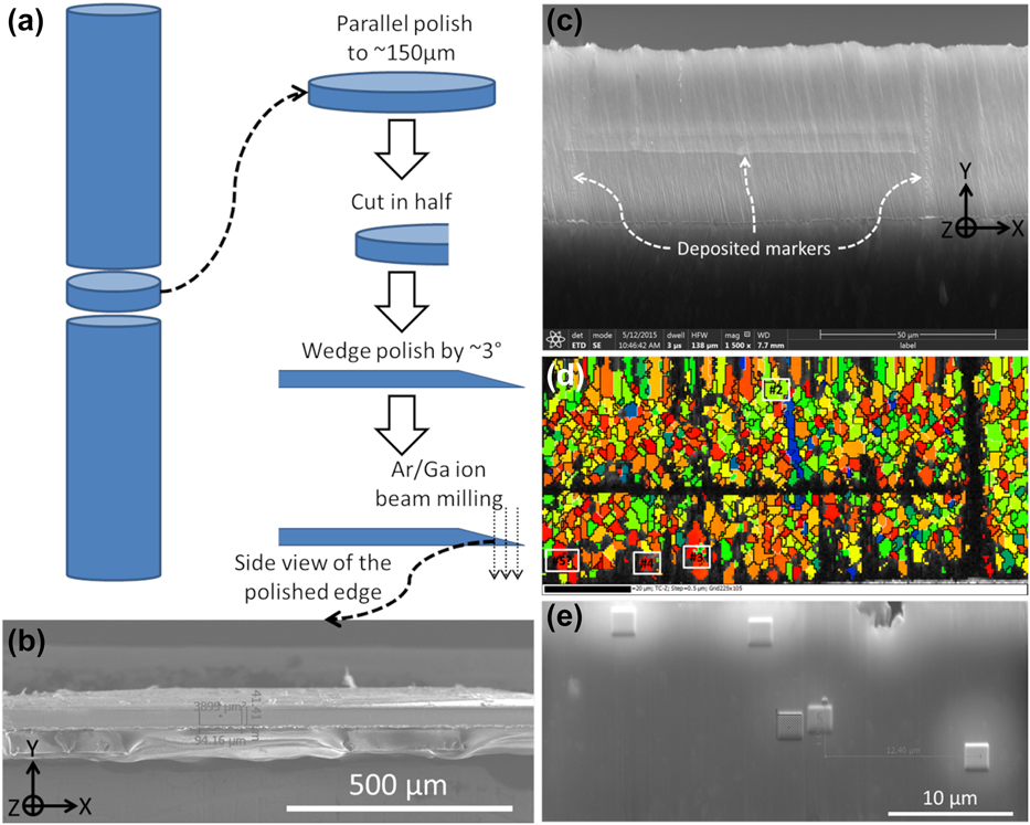
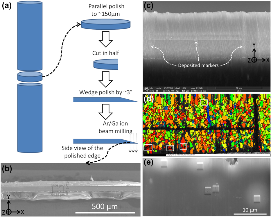
Therefore, significant efforts were devoted to developing the optimal sample preparation routes for the in situ TEM studies. While a few pillars were prepared following the general route described in the literature [Reference Xie, Shrestha, Cao, Felfer, Wang, Liao, Cairney and Ringer25], most of the pillars in this study were prepared from wedge-polished thin foil through the route illustrated in Fig. 5. Slices of ∼500 μm were sectioned from the as-extruded FG Mg–Y bar using a wire saw with minimal speed and load. Then, parallel grinding/polishing and wedge polishing were carried out using the Allied MultiPrep tool (Allied High Tech Products, Inc., Rancho Dominguez, California). It was noted that all polishing procedures were finished with the finest lapping film (0.1 μm) to minimize damage. The wedge side was cross-section polished by either Ar+ ion milling (JEOL cross-section polisher SM-09010) or focused ion beam (FIB, FEI Strata 235 or FEI Scios); in this way, the width of the cross-section area could be controlled by varying the amount of material to mill away. After several trials, a width of ∼40 μm [see Figs. 5(b) and 5(c)] was chosen to encompass a statistically large-enough amount of grains while avoiding the high cost of subsequent machining of a large width/area by FIB. Then, a selected area was marked by depositing a few thin lines of tungsten (W) using FIB [Fig. 5(c)]. The corresponding EBSD (Oxford Instruments) map is shown in Fig. 5(d). The rainbow color code is based on the angle (φ angle hereafter, analogous to the φ angle in [Reference Zhang, Wen, Kumar, Chen, Zhang, Beyerlein, Schoenung, Mahajan and Lavernia21]) between the c-axis of each grain and the Z direction, namely, the loading direction for subsequent in situ deformation, as shown in Fig. 5(c). Based on the φ angle, several grains were selected [Fig. 5(d)], and subsequently marked with W deposits. Figure 5(e) shows examples of square-shaped W deposits on the top of target grains. These deposits also serve as protective layers for subsequent FIB milling. It is noted that the broad Ar+ beam cross-section polisher is an ideal instrument for our sample preparation route because (i) it polishes a fairly large (up to several mm2) cross-section area [see Fig. 5(b) e.g.,] so that multiple grains with desired orientations could be located and (ii) the polishing quality is excellent as EBSD maps such as Fig. 5(d) have a hit rate of up to 70%.
(a) Schematic illustration for preparation of cross-section. (b) macroscopic SEM view of ion polished cross-section. (c) Enlarged SEM view of a selected area with deposited W as markers. (d) EBSD map corresponds to (c), showing examples of target grains in white boxes. (e) Examples of W markers/protection layers deposited on target grains.
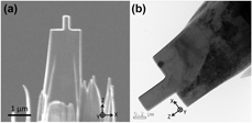
Subsequently, Mg–Y nano-pillars were machined from marked grains using FIB [Reference Ye, Mishra, Sachdev and Minor27]. A typical pillar is shown in the SEM view [Fig. 6(a)] and TEM view [Fig. 6(b)]. The corresponding coordination system is inserted to guide the eye as the viewing plane changes from the cross-section EBSD view to an SEM/TEM view. In situ deformation for all Mg–Y nano-pillars was performed in a JEOL 3010 TEM (operated at 300 KeV) equipped with a Gatan Orius CCD camera and a Hysitron PI-95 Pico-indenter system [Reference Ye, Mishra, Sachdev and Minor27], under displacement-control mode with a loading rate of ∼2 nm/s (corresponding to a ∼2.5 × 10⁻³/s quasi-static strain rate). In Fig. 6(b), one might notice a thin layer of FIB damage, which is inherently inevitable in nano-pillar preparation using FIB. Jeong et al. demonstrated that by annealing the as-FIB-prepared pure Mg pillars at elevated temperature, they were able to achieve almost damage-free pillars. However, one primary goal of this in situ deformation study was to reveal the effects of super-saturated solid solution Y element on deformation mechanisms in the as-extruded Mg–Y material. Therefore, any heat treatment for the bulk material or the pillars may alter the solid solution/clustering condition of Y atoms, thus forfeiting meaningful comparison.
SEM (a) and TEM (b) views of a typical pillar.

Pillar-on-pillar design to mediate LS
One can note in Figs. 6(a) and 6(b) that the in situ TEM samples were made in the way that a nano-pillar sat on a micro-sized “pillar.” This setup was used to mediate the inherent lateral stiffness (LS) in nano/micro-pillar compression experiment. In compression testing for bulk materials, lubricants (e.g., graphite) are often applied to the top and bottom surfaces of the compression sample to prevent the sample from getting attached to the testing machine during deformation. However, in micro/nano-pillar compression, there is inevitable friction between the top surface of a pillar and the indenter during indentation, as well as nano-plasticity exposing fresh material that can easily adhere to the compression platten. If shear deformation was to occur analogous to deforming bulk material, the top surface of the pillar has a tendency to shift laterally but is not able to due to the friction. Essentially, the pillar is laterally confined at least during the early stage of compression. This LS would make accurate interpretation of deformation data complicated [Reference Husser, Lilleodden and Bargmann58, Reference Kuroda59], especially for the less symmetric deformation of HCP Mg [Reference Husser, Lilleodden and Bargmann58]. In recent years, researchers have come up with customized experimental setups [Reference Daum, Dehm, Clemens, Rester, Fischer and Rammerstorfer60, Reference Kirchlechner, Keckes, Motz, Grosinger, Kapp, Micha, Ulrich and Dehm61, Reference Uchic, Shade and Dimiduk62, Reference Shade, Wheeler, Choi, Uchic, Dimiduk and Fraser63], enabling free lateral movements of the indenter, thus mediating LS.
Considering the limited access to such customized indenter systems enabling free movements for the top of pillars, Kiener et al. [Reference Kiener, Motz and Dehm64] came up with an alternative approach in that they FIB milled a Cu micro-pillar out of the tip of an etched Cu needle. In this way, the bottom of the pillar was free to move laterally by the slightly elastic “wiggling” of the long needle, thus effectively mediating LS. Comparing the deformation behavior of this pillar design with that of commonly prepared pillars having strong LS, they revealed that LS generally lead to artificially higher shear stresses. Specifically, LS played an even more important role for pillars oriented for single slip [Reference Kiener, Motz and Dehm64], as it may impede or delay the apparent shear of the pillar (i.e., occurrence of distinct slip trace).
Analogous to the “pillar-on-needle” design by Kiener et al. [Reference Kiener, Motz and Dehm64], the “pillar-on-pillar” design for Mg–Y nano-pillars herein would also effectively mediate LS, as schematically illustrated in Fig. 2. In Fig. 2(a), the dark blue nano-pillar sits on the light blue micro-pillar, with the black indenter on top and the base bulk material at the bottom (also dark). The small and large yellow dashed boxes mark the initial positions of the nano- and micro-pillars, respectively, whereas the red dashed line represents the loading axis. In Fig. 2(b), as indentation progresses and shear event occurs (see the red arrow beside the nano-pillar), obviously the top of the nano-pillar remains attached to the indenter due to LS. Meanwhile, the bottom of the nano-pillar is able to move to the right: thanks to the slightly elastic “wiggling” of the micro-pillar (see the red arrow beside the micro-pillar), thus compensating the lateral movement necessitated by the shear. Note that while the top of the nano-pillar remains aligned with the initial loading axis, the bottom of the nano-pillar and the whole micro-pillar are able to depart slightly from the initial loading axis, i.e., their initial positions. In Fig. 2(c), after the shear event and the unloading of the indenter, the micro-pillar elastically wiggles back to its initial position (i.e., large yellow dashed box), enabling the bottom part of the nano-pillar to also return to its initial position (i.e., small yellow dashed box), whereas the top part has obviously been sheared to the left (see the red arrow).
Supplementary material
To view supplementary material for this article, please visit https://doi.org/10.1557/jmr.2019.124.
Acknowledgments
This work was supported by the National Science Foundation (NSF CMMI-1437327) and 111 Project of China (No. B13035). The authors also acknowledge the support from the Molecular Foundry, which is funded by the Office of Science, Office of Basic Energy Sciences of the US Department of Energy under Contract No. DE-AC02-05CH11231. Experimental assistance from Mr. John Turner and Dr. Joshua Kacher is highly appreciated.