1. Introduction
With the increasing demands for high productivity, various industrial fields, including semiconductor manufacturing, medical applications, and especially automatic microassembly, have steadily adopted parallel manipulators (PMs) due to their dynamic performance and kinematic precision. PMs with flexible links represent a promising design alternative to these applications since they can perform as PMs with rigid links if adequate control strategies are implemented. Flexible PMs can achieve higher speed and acceleration, lower energy consumption, and higher payload-weight ratio due to their lightweight components [Reference Dwivedy and Eberhard1–Reference Firoozabadi, Ebrahimi and Amirian3]. However, this design alternative may be subjected to unwanted vibrations in the manipulator, leading to longer settling time and decreased tracking accuracy. These residual vibrations raised from inertial forces may not only reduce the accuracy of the end effector but also increase the instability of the PM [Reference Zhang, Mills and Cleghorn4–Reference Geronel, de Oliveira and da Silva6]. In this sense, several control strategies have been proposed to attenuate the undesired vibration of flexible PMs.
It is a fact that designing efficient control strategies for PMs with flexible links is a challenging task. Traditionally, the current works combine the use of kinematic equations from the rigid links and additional strategies to compensate for the flexibility. For instance, two hybrid model-based control strategies are investigated for a flexible parallel planar manipulator [Reference Colombo and da Silva7]. Two feedback loops are employed to calculate the corresponding control law, where one exploits the encoder’s measurement and the inverse kinematic model, assuming a PM with rigid links, and the other investigates the design of an LQR/LQG strategy. The proposed strategies are experimentally evaluated and compared with a conventional PID, which shows a positive attenuation of the steady-state error and undesired vibration response. Despite demonstrating vibration attenuation capabilities, the strategies proposed by Colombo et al. [Reference Colombo and da Silva7] require the derivation of limited-sized dynamic models of the flexible PMs, which is a challenge. Moreover, Morlock et al. [Reference Morlock, Burkhardt, Seifried and Eberhard8] investigated the design of an input–output feedback linearization equations for flexible link parallel robots. Geometric and servo constraints are employed to calculate the corresponding control law. A dynamic, flexible model inversion is also combined with the linear quadratic regulator (LQR) to improve the trajectory tracking of the end-effector efficiently. A feedforward-based control is designed, based on a two-point boundary value problem, to calculate the desired trajectory. To compensate for the adverse impact of elastic deformation, the state feedback, based on LQR, is used. The proposed strategy shows a superior tracking trajectory performance of the flexible link parallel manipulator. It is important to highlight that due to the complexity of modeling a flexible PM, the desired state trajectories are obtained from the rigid-body inverse kinematics. A nonlinear control, based on the Lyapunov approach, is also investigated for flexible PMs [Reference Eberhard and Ansarieshlaghi9]. While drivers’ positions and velocities are measured by two optical encoders, full bridge strain gauges are attached to the flexible links to measure their deformation. Two stages are used to design the nonlinear, including the feedforward and feedback loops. Regarding the feedforward loop, the desired trajectory is calculated using a two-point boundary value, while the feedback loop calculates the corresponding control input based on the reduced nonlinear dynamics of the PM.
The derivation of reduced models is a demanding task. Nonlinear estimators have been investigated to tackle this issue. For instance, a nonlinear estimator, based on the unscented Kalman filter (UKF), is combined with the kinematics to efficiently guide the desired trajectory of a flexible PM [Reference Morlock, Burkhardt and Seifried10]. The state estimator is employed as a feedback control to calculate the end-effector pose (position and orientation) and velocity. For the estimator, the kinematic is treated by a projection tangential to the manifold, which is calculated according to the QR decomposition. Then, the UKF is employed to obtain the dependent coordinates using the Newton–Raphson method. Actuator position and strain gauges are also employed to validate the results of the proposed method. The results reveal a better performance in terms of vibration attenuation and trajectory accuracy. Experimental analysis regarding feedforward control strategies for PMs with flexible links are investigated by Burkhardat et al. [Reference Burkhardt, Seifried and Eberhard11]. A cascade control configuration is designed for the proposed strategy. While the outer loop is able to amplify the position error, the inner loop uses the servo controllers to accomplish the final task. Positions and velocities are calculated to obtain the corresponding control law, which are acquired respectively by the servo drives and reconstructed by the Kalman filter.
Alternatively, some works exploit strain gauge sensors and piezoelectric lead zirconate titanate (PZT) sensors/actuators to directly measure or actuate in the undesired vibrations. For instance, a hybrid dynamic model-free control strategy is proposed by da Silva et al. [Reference da Silva, Colombo, de Oliveira and de Oliveira12]. The hybrid strategy comprises two control loops: a position-based visual servo and a strain-based feedback control strategy and no estimator is employed. The position-based visual control uses a camera to track the end-effector pose, while the strain-based employs strain gauges to measure the links’ deformations. The strain-based feedback loop uses the sliding mode control (SMC) methodology to reduce the system’s vibration. Therefore, this second loop is employed to attenuate the undesired vibration since the visual servo loop, based on a PID strategy, can collect the images at a limited rate. Despite reducing the overshoot response by an average of 36%, a methodology to tune the SMC’s gains is lacking.
Active vibration control using PZT sensor/actuator pairs arises as a promising alternative to deal with the undesired vibrations of the parallel manipulator. However, there is a scarce number of papers that explore the active vibration control in flexible PMs. A PZT ceramic actuator, based on the active damping method, is used to attenuate the deformation of 2-PRRRP manipulators’ links during accelerated trajectories [Reference Valizadeh and Shariatee13]. The PZT is attached to the link’s surface to generate a shear force that reduces the adverse effects of flexibility. Assumed mode method and a PD feedback control, based on linear velocity feedback (L-type) are combined to attenuate the residual vibration of the flexible links. Moreover, PZT stacks are employed as sensors and actuators, as an active vibration control, of a 3-PRR parallel manipulator [Reference Zhang, Wang, Mills and Cheghorn14]. The PZT control is formed by two PZTs, which are located at the same position on opposite sides of the flexible links. The first PZT acts as a sensor, whereas the second PZT acts as an actuator. A state-place model is designed to calculate the corresponding control input and output voltages acquired from the PZT sensors that are applied to the PZT actuators. Then, a SRFC is developed to suppress the residual vibration caused by the flexible links. Note that in this case, only one link was considered flexible.
On the other hand, Zhang et al. [Reference Zhang, Mills and Cleghorn15] assessed the design of an active vibration control strategy for a 3-PRR parallel manipulator with three flexible links. The proposed strategy is implemented using three pairs of PZTs (placed on both sides of the flexible links) based on modal strain rate feedback (MSRF) control. The PZTs, used for sensors, are employed to acquire the signals from the flexible links and transform them into the corresponding outputs for the PZT actuators. Modal filters and second compensators based on MSRF are combined to automatically estimate modal coordinates or velocities and reduce the amplified noises, respectively. Similarly, Zhang et al. [Reference Zhang, Li, Zhang and Zhang16] investigated the use of three pairs of PZTs sensors and actuators, placed on different parts of the links. An electrical equivalent model, i.e., a voltage sources series with a capacitor, is employed to measure the vibration amplitude, and then calculate the corresponding sensing voltage. Experimental results show positive results when using PZTs, for both sensors and actuators, to attenuate residual vibration of flexible links. Similarly, the PD feedback control is combined with strain rate feedback control (SRFC) to improve the tracking trajectory and attenuate the residual vibration of the flexible links [Reference Liang, Song, Sun and Jin17]. The PZTs are located on both sides of the flexible links at three locations, acting as sensors and actuators. The axial elastic deformation is neglected since its contribution to the total deformation is not significant [Reference Zhang, Li, Zhang and Jin18].
This work proposes a two-loop active vibration control strategy, using strain gauges and PZT actuators, to compensate for the undesired effect of the flexibility on a PM 3RRR. A pose control loop exploits the SMC using data collected from images acquired by an oCam-5CRO-U camera; an active vibration control loop uses strain gauge sensors and PZT actuators to generate the corresponding control law to attenuate the undesired vibration and deflections. In contrast to the works previously mentioned, strain gauges are responsible for measuring the deformation of each link, and after being treated by digital filters, these signals are applied to the PZT actuator. For a robust analysis of the proposed method, ten experimental trials are performed for each control strategy and two different configurations. An average signal is then calculated to represent the characteristics of both configurations.
The main contributions of this work are
-
• The proposal of a two-loop active control strategy for vibration attenuation of flexible parallel manipulator considering strain gauges sensors signals and PZT actuators;
-
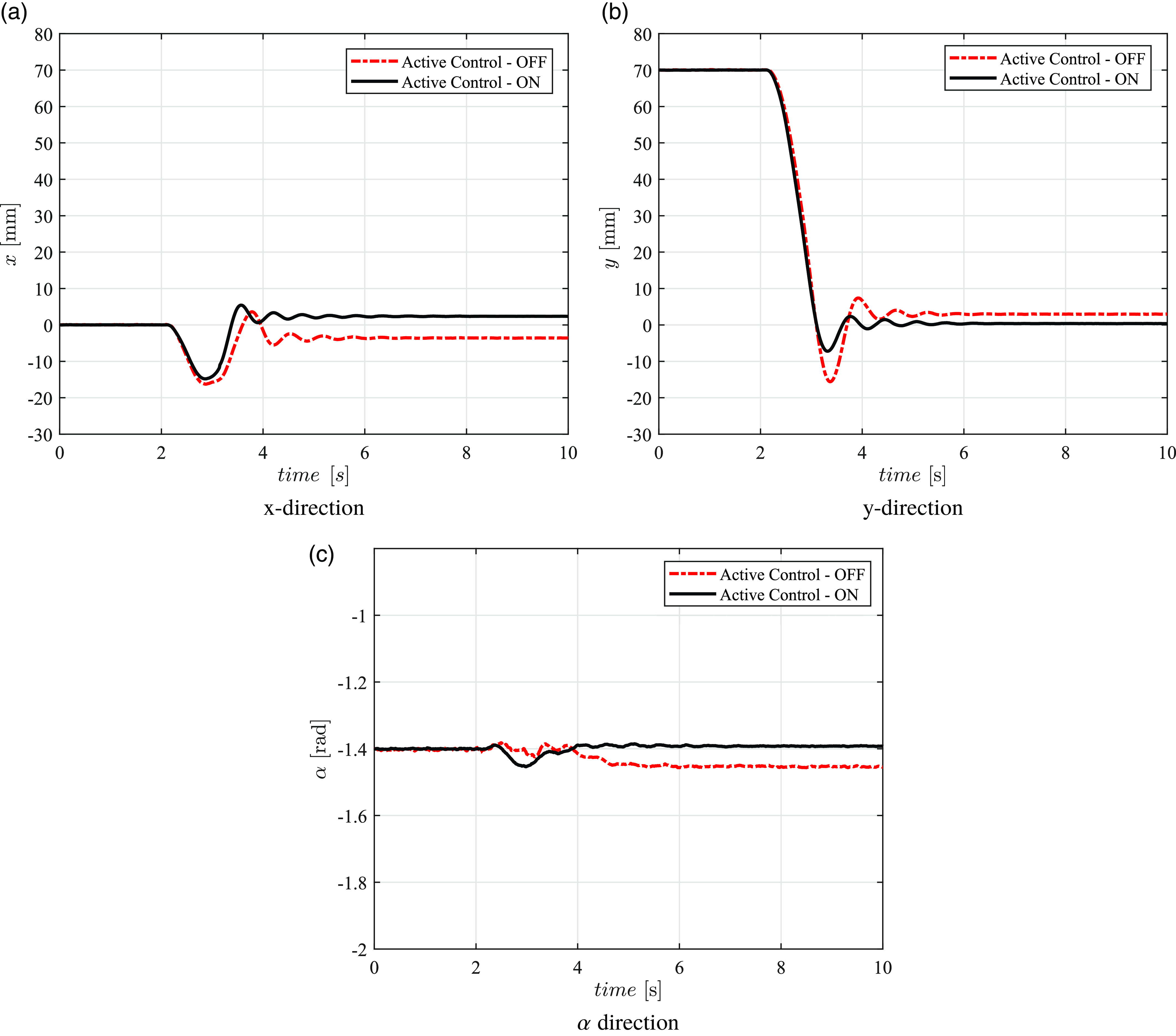
• The experimental investigation of the impact in the dynamic performance of the attachment of PZTs in all the flexible links of a PM 3RRR; and
-
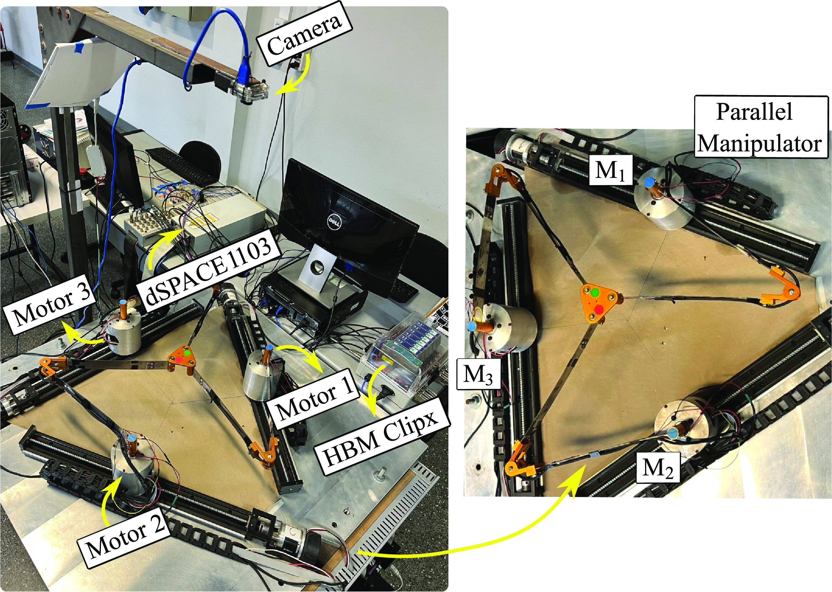
• The experimental evaluation of the two-loop active control strategy in an instrumented prototype (see Figure 1).
The paper is organized as follows. Section 2 presents the methodology and instrumentation employed for the work evaluation. Section 3 details the control development, highlighting the development of both the pose control and active control loops. Section 4 presents the results, comparing and improving the proposed control design, while Section 5 presents the paper’s main conclusions.
2. Methodology
This section illustrates the flexible parallel manipulator and the required instrumentation. Figure 1 shows the instrumentation used to control the prototype. Note that in this case, the prototype is formed by a 3PRRR system, which presents some redundant joints. However, the prismatic joints are blocked to assume a 3RRR configuration. Based on the 3RRR parallel manipulator, three chains are used to define the whole system, where each chain is composed of three revolute joints. Note that the letter R corresponds to the revolute joints, such that the underlined letter is an active joint, and the other two are passive joints. In this work, the three active joints (one from each kinematic chain) are represented by the motors (as seen by the Motor 1, Motor 2, and Motor 3). Different sources of gravity, nonlinearities, manufacturing deviation, and uncertain friction forces can significantly affect the parallel manipulator. This work studies a model-free control strategy, due to the high complexity of developing a dynamic model for this flexible parallel manipulator.
Instrumentation of the prototype – 3RRR with flexible links.

2.1. Instrumentation scheme
The parallel manipulator 3RRR is composed of three kinematic chains, formed by two revolute passive joints and one active joint, in each chain. The motor, i.e., the active revolute joints, is represented by Motor 1 (
 $M_1$
), Motor 2 (
 $M_2$
), and Motor 3 (
 $M_3$
) as noted in Figure 1. Assuming that the zero of coordinates is located in the center of the workspace, the coordinates for the three motors are, respectively, described by
 $M_1(187.5,235.0)$
mm,
 $M_2(187.5, 235.0)$
mm, and
 $M_3(-187.5,0)$
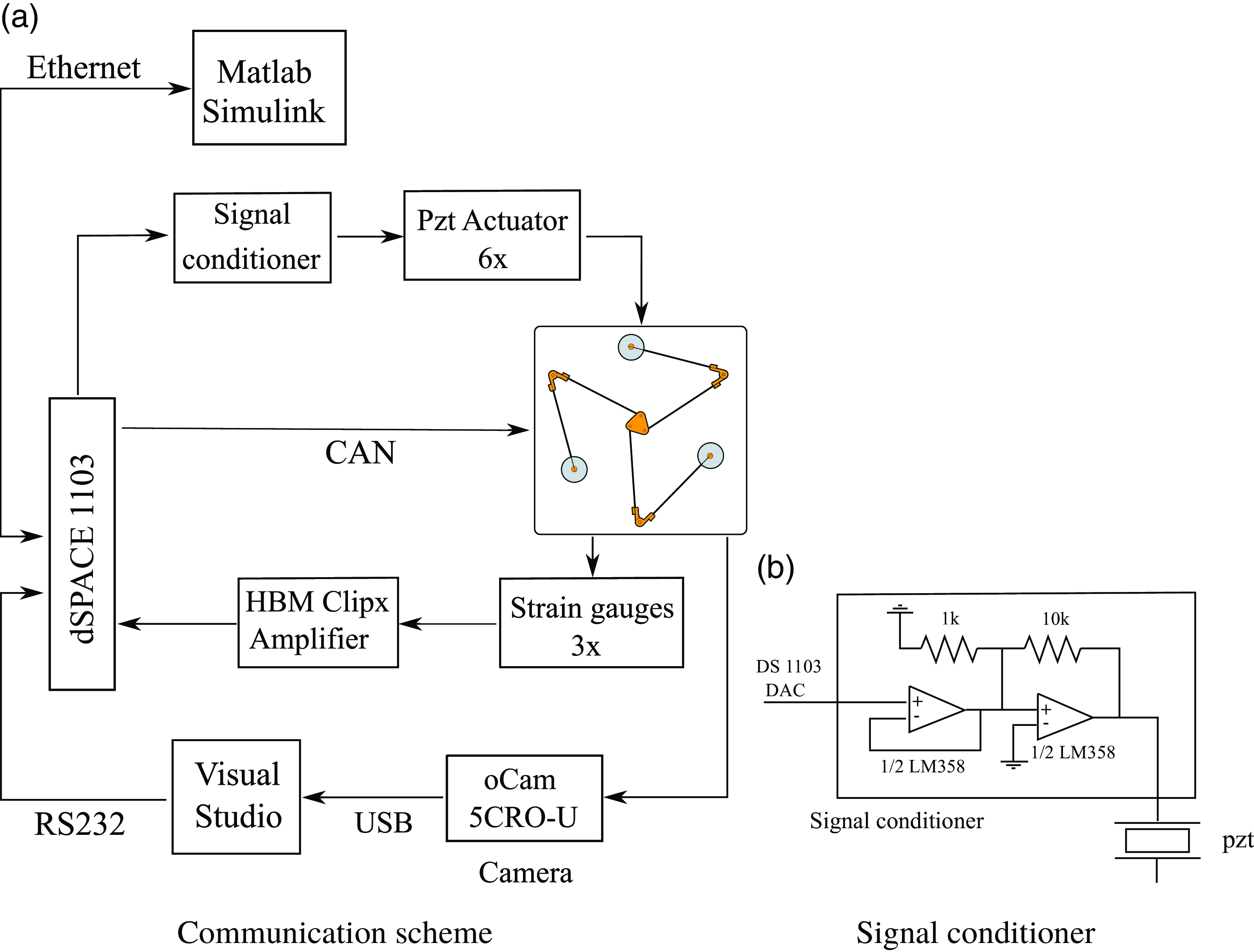
mm. The active revolute joints are powered by brushless Maxon EC60 motors, with power of 100W and a rate of current of 2.3 A. The motors are coupled to GP52 C planetary reducers with a reduction of 3.5:1, which is able to provide a nominal rotation of 1200rpm and 0.82 Nm of torque. The Maxon EPOS2 50/5, with a power supply of up to 50 Vdc and a current of 5 A, is employed to generate the actuation signal in each motor. Moreover, the dSPACE 1103 is the control board and is employed to establish the communication between the computer and the prototype. The communication between the EPOS controllers and the dSPACE 1103 is conducted via CAN protocol, with a 250kbit/s transmission rate and a
 $T_s$
= 0.001 s sampling time. Then, Ethernet is used to establish the board and computer communication. Figure 2 depicts the instrumental scheme of the prototype.
Schematic illustration of the prototype communication.

The six flexible links are made of AISI 6150 spring steel. All six links present the same dimension with a length of
 $318.5$
mm, height of
 $7.5$
mm, and width of
 $0.7$
mm, and the mass of each link correspond to
 $7.35$
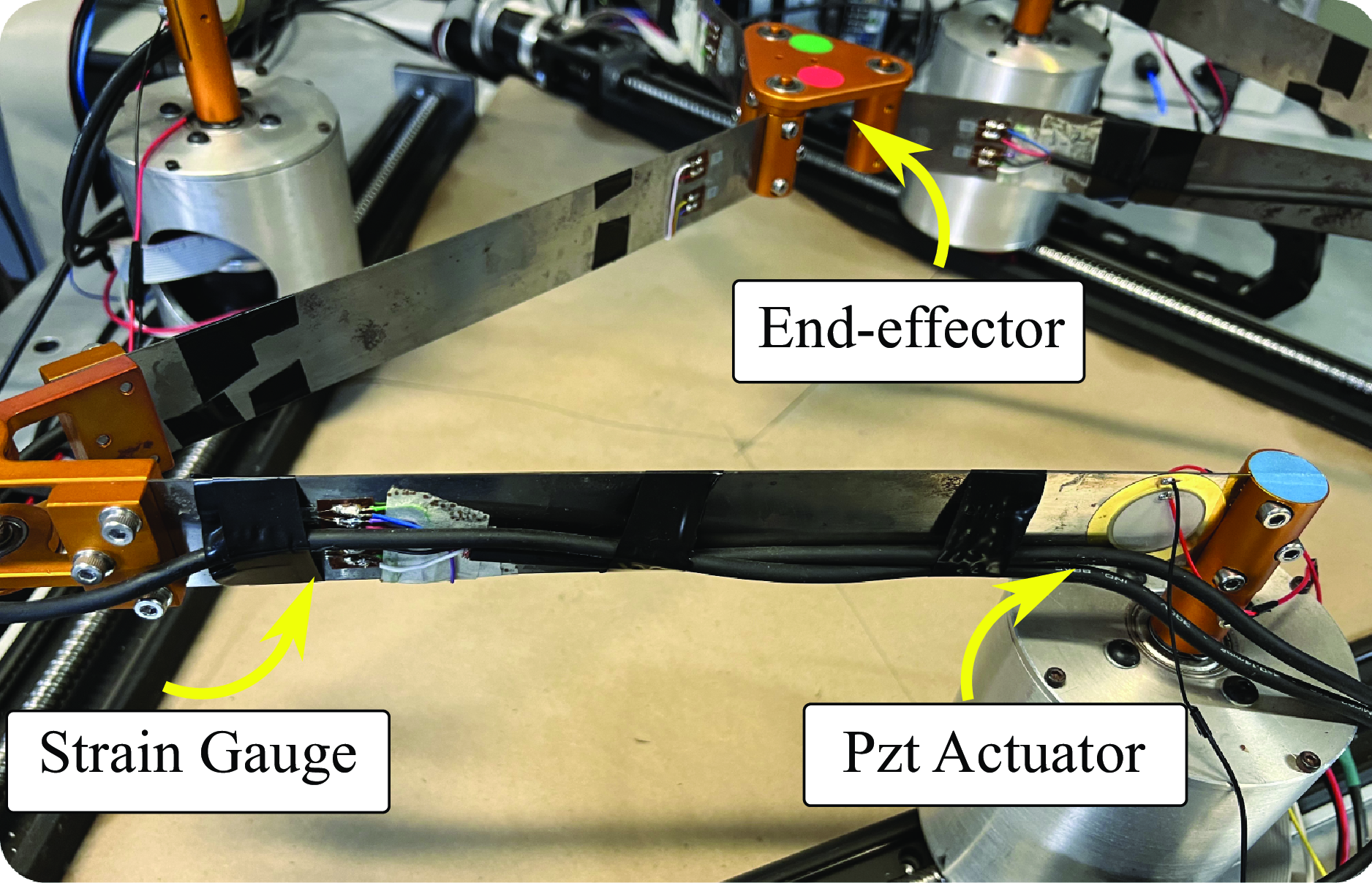
g. Due to the flexibility of the links, a deformation can be observed during the movement. This deformation is collected by HBM 350-E strain gauges, as noted in Figure 3. The strain gauges, represented by a full-bridge configuration, are placed at the endpoint of each link since the dynamic measurement of deflection and angle requires this location to better control a flexible link. The endpoint of the position and angle approximates the beam shape dynamic. The corresponding signals from the strain gauges pass through HBM HB40 CLIPX signal amplifiers before being sent to the dSPACE 1103. Two circular piezoelectric disks are attached to both sides of the flexible links, closer to the corresponding motors. The pair is used in series to amplify the control effect. The active control signal is calculated in real-time using signals collected by the strain gauges of the same link. The signal control is fed from the DAC outputs of the dSPACE through an active signal conditioning circuit powered by an external power supply with sources of
 $\pm 12$
V. The circuit consists of an operational amplifier (OA) LM358 set as a voltage buffer and a negative gain stage.
A picture of the strain gauges are PZT actuators used for the control strategy.

A camera, oCam-5CRO-U with a USB 3.0 interface and CMOS rolling shutter image sensor, is used to collect the manipulator’s real-time images. The camera is calibrated according to Zhang’s method [Reference Zhang19]. The oCam-5CRO-U camera is fixed above the workspace, with a resolution of 640
 $\times$
480 pixels, and a maximum frame rate of 120 fps (frames-per-second). The images collected by the camera are processed on a computer, using using a C++ script with the Visual Studio software, to specify the position and angle of the end effector during its movement. These collected data are transmitted to the dSPACE 1103 controller board via RS232 protocol at a 120 fps rate.
2.2. Image processing algorithm
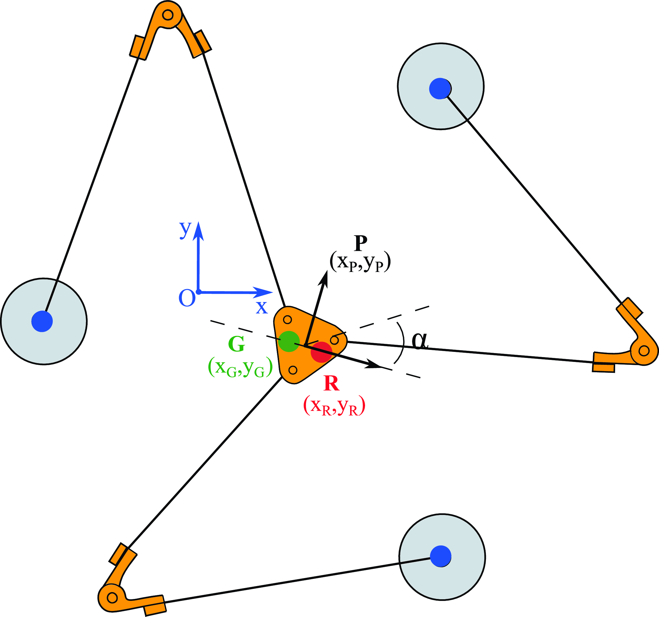
The image processing algorithm is designed to process images captured by a camera in real-time and image features. The images are periodically obtained by a camera to estimate the pose of the end effector, i.e., its position and orientation, which can be represented by the corresponding vector
 $\mathbf{X} = [x_P, y_P, \alpha]^T$
. While the two first terms
 $(x_P, y_P)$
correspond to the linear position of the end effector, the last term
 $\alpha$
defines its angular orientation. After calculating the pose of the end effector, these coordinates are employed as a control signal in control strategies. The parallel manipulator is assumed to be a planar mechanism, which restricts its movement to a plane that coincides with the
 $x-y$
plane with
 $z=0$
of the manipulator coordinate system. The oCam CRO-U camera is held fixed over the workspace, allowing the captured images and the end-effector’s motion to be represented on parallel planes. Figure 4 illustrates the references used to calculate the end-effector’s pose.
Schematic illustration of the 3RRR prototype, showing the position-based visual servo control.

Some initial steps are required to implement the Image Processing Algorithm. Note that in Figure 4, there are three blue circular markers placed atop each active revolute joint (motor), and two colored markers (a red and a green one) fixed atop the end-effector surface to represent its coordinates over the time. Based on the three blue circular markers, the algorithm is able to determine the center of the workspace by its geometrical reference, represented by point 0. Then, green and red circular markers, defined by the points
 $G$
and
 $R$
, are used to detect the end-effector’s pose. These markers of the end-effector surface are used as a colored pattern to be tracked by the computer vision algorithm since there are no other similar colors in the 3RRR workspace. While the position of the green markers is expressed by the vector
 $(x_G, y_G)$
, the red marker can be defined by the vector
 $(x_R,y_R)$
. Regarding the point’s location, an algorithm based on filters is developed. The images acquired by the camera are decomposed in RBG and HSV color spaces employing the OpenCV library. The algorithm is able to generate six matrices, whose elements range from 0 to 255. The elements are defined as
 $\mathbf{R}$
,
 $\mathbf{B}$
,
 $\mathbf{G}$
,
 $\mathbf{H}$
,
 $\mathbf{S}$
, and
 $\mathbf{V}$
. Then, filters are also used to identify the blue, green, and red regions, expressed by the corresponding matrices
 $\mathbf{B}_f$
,
 $\mathbf{R}_f$
and
 $\mathbf{G}_f$
. Based on the filtering conditions, a number 1 is assigned for the corresponding element, and 0 otherwise. For instance, the elements of matrix
 $\mathbf{G}_f$
are one if the pixels correspond to green. The proposed filter is expressed by the next Eq. 1
 \begin{equation} \begin{array}{l} \mathbf{T}_{min} \lt (\omega _R \mathbf{R} + \omega _G \mathbf{G} + \omega _B \mathbf{B}) \lt \mathbf{T}_{max} \\ \\ \mathbf{H}_{min} \lt \mathbf{H} \lt \mathbf{H}_{max} \end{array} \end{equation}
where
 $\omega _i$
, (i = R,G,B) are the weighting factors of the threshold matrices
 $\mathbf{T}_{min,max}= t_{min,max} \mathbf{1}$
and
 $\mathbf{H}_{min,max}= h_{min,max} \mathbf{1}$
are the lower and upper boundaries of the Hue scale matrix, defined by
 $\mathbf{H}$
. According to these color references, the algorithm can calculate the end-effector’s pose over the manipulator’s motion. The point
 $P$
 $(x_P, y_P)$
and the
 $\alpha$
angle (line orientation between the points
 $G$
and
 $R$
in relation to the x-direction) are then defined as
 \begin{equation} \begin{array}{l} x_ p = \frac {1}{2} (x_G + x_R), \\ \\ y_ p = \frac {1}{2} (y_G + y_R), \\ \\ \alpha = \arctan \;\Big (\frac {x_R - x_G}{y_R - y_G}\Big). \end{array} \end{equation}
Further details of image processing algorithm can be found in [Reference Colombo and da Silva7].
3. Control design
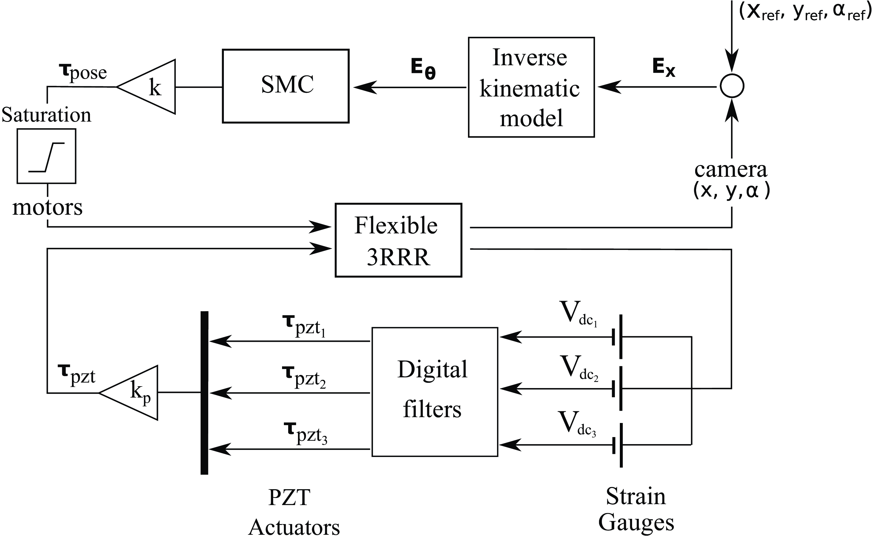
Since the flexible 3RRR prototype has three active revolute joints; their inputs are required to fully control the prototype, which is expressed by the corresponding vector
 $\boldsymbol {\tau }_{pose}$
. Besides these inputs, actuation is also delivered by the PZT actuators, which is expressed by
 $\boldsymbol {\tau }_{pzt}$
. The proposed control law input comprises two strategies, one from the camera and the other from the strain gauges and PZT actuators. Figure 5 shows the schematic illustration of the control strategy employed in this work. While the camera exploits the end-effect’s pose, considering a SMC methodology, the combination of strain gauges and PZT actuators is used to create a control law to attenuate the undesired vibration caused by the flexible links.
Control strategy scheme.

3.1. Pose control loop
The inverse kinematic model (IKM) is employed to design the control input related to the pose of the end effector, as studied by [Reference Siciliano, Sciavicco, Villani and Oriolo20]. Note that due to the high complexity of calculating the equations from the dynamic model, these relations are obtained considering a 3RRR with rigid links. The Jacobian matrix establishes the relation between the velocities from the joint space to task space, defined by
 $\dot {\mathbf{X}}=\mathbf{J}\dot {\boldsymbol {\Theta }}$
. Moreover, the control is designed based on SMC methodology, with the following control input
 $\boldsymbol {\tau }_{pose}$
. The inputs from the camera loop are calculated based on the errors, as defined by
 \begin{equation} \mathbf{E}_{\boldsymbol {\Theta }} = \mathbf{J}^{-1} \mathbf{E}_{\mathbf{X}} \end{equation}
where
 $\mathbf{E}_{\mathbf{X}}$
is defined by the difference between the reference and calculated states, as seen by
 $\mathbf{E}_{\mathbf{X}} = \mathbf{X}_{ref} - \mathbf{X}$
, such that
 $\mathbf{X}_{ref}=(x_{ref}, y_{ref}, \alpha _{ref})$
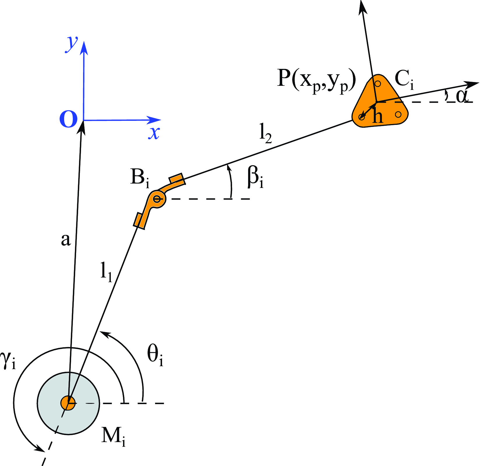
. Figure 6 depicts a single chain of the parallel manipulator to better illustrate all the parameters used to define the kinematic modeling.
Illustration of a single kinematic chain of the prototype.

As mentioned, the parallel manipulator 3RRR has three kinematic chains, which can be defined by
 $i=1,2,3$
. Each chain is formed by three revolute joints, where one represents the active joint (the corresponding motor), and the rest are passive joints. The motor is defined by
 $M_i$
, whereas the other two passive joints are defined by
 $B_i$
and
 $C_i$
, as seen in Figure 6. Moreover,
 $l_1$
and
 $l_2$
are the length of the flexible links, related to the links of
 $M_i$
-
 $B_i$
and
 $B_i$
-
 $C_i$
, respectively. The orientation angles of the first and second links are defined by
 $\theta _{i}$
and
 $\beta _{i}$
, while the parameters
 $a$
and
 $h$
define, respectively, the distance between the center of the workspace and each motor and the distance between
 $P$
and
 $C_i$
. Finally, the angle
 $\gamma _i$
represents the orientation of the prismatic joint relative to the reference. Since the prismatic joints are blocked, these angles are assumed to be constant, as seen in Section 4. The angles
 $\theta _{i}$
, calculated by the IKM, can be represented as
 \begin{equation} \theta _{i} = 2 tan^{-1}\left (\frac {-e_{i3} \pm \sqrt {e_{i2}^{2} + e_{i3}^{2} - e_{i1}^{2}}}{e_{i1} - e_{i2}}\right), \end{equation}
where
 $e_{i1} = (x + h\cos (\alpha + \gamma _i) - a\cos (\gamma _{i}))^{2} + (y + h\sin (\alpha + \gamma _i) - a\sin (\gamma _{i}))^{2} + l_{1}^{2} - l_{2}^{2}$
,
 $e_{i2} = - 2l_{1}(x + h\cos (\alpha + \gamma _i) - a\cos (\gamma _{i}))$
, and
 $e_{i3} = - 2l_{1}(y + h\sin (\alpha + \gamma _i) - a\sin (\gamma _{i}))$
. The
 $\pm$
sign indicates the manipulator’s working mode, which can be negative or positive. In this work, a negative representation is assumed for all the kinematic chains. In addition,
 $\beta _{i}$
is obtained by
 \begin{equation} \beta _{i} = tan^{-1}\left (\frac {y + h\sin (\alpha + \gamma _i) - a\sin (\gamma _{i}) - l_{1}\sin (\theta _{i})}{x + h\cos (\alpha + \gamma _i) - a\cos (\gamma _{i}) - l_{1}\cos (\theta _{i})}\right). \end{equation}
The relation between the velocity of the end-effector
 $\dot {\mathbf{X}}$
and the angular velocity of the active joints
 $\dot {\boldsymbol {\Theta }}$
can be calculated by
 \begin{equation} \mathbf{A}\dot {\mathbf{X}} = \mathbf{B}{\dot {\boldsymbol {\Theta }}} \end{equation}
where
 $\mathbf{A}$
is defined by
 $\mathbf{A} = [a_{i1}, a_{i2}, a_{i3}]$
, such that
 $a_{i1} =l_{2}\cos (\beta _{i})$
,
 $a_{12} = l_{2}\sin (\beta _{i})$
and
 $a_{i3} = l_{2}h\sin (\beta _{i} - \gamma _i - \alpha)]$
, while
 $\mathbf{B}$
is a diagonal matrix that can be defined by
 $b_{ii} = l_{1}l_{2}\sin (\beta _{i} - \theta _{i})$
. The Jacobian matrix, defined by the relation of velocities from the joint space and task space, is represented by
 $\boldsymbol {J} = \boldsymbol {A}^{-1}\boldsymbol {B}$
if
 $\boldsymbol {A}$
. A more detailed representation of the kinematic and dynamic models of 3RRR with rigid links can be found in [Reference de Carvalho Fontes, Colombo, da Silva and da Silva21]. Regarding the design of pose control, based on the SMC methodology, a sliding surface is initially chosen, defined by
 $\textbf {s}_i = \dot {\textbf {E}}_{\theta } + \boldsymbol {\lambda } \mathbf{E}_{\theta }$
, where
 $\mathbf{E}_{\theta }$
and
 $\dot {\textbf {E}}_{\theta }$
are the error and its time derivative, and
 $\boldsymbol {\lambda }$
is a diagonal matrix of
 $\lambda$
, where
 $\lambda$
is a tuning parameter related to the closed loop bandwidth. Similar to
 $\mathbf{E}_x$
, the error
 $\mathbf{E}_{\theta }$
is defined by the difference between the reference and calculated states, as seen by
 $\mathbf{E}_{\theta } = \boldsymbol {\Theta }_{ref} - \boldsymbol {\Theta }$
, where
 $\boldsymbol {\Theta } = (\theta _1, \theta _2, \theta _3)$
. Finally, the corresponding control law is defined by
 \begin{equation} \boldsymbol {\tau }_{pose} = -K \,sign(\mathbf{s}) \end{equation}
where
 $K$
is the gain of the SMC. In this case, the gains of the proposed control (SMC) are experimentally tuned to achieve a positive tracking performance of the end effector. Since the parameters were estimated experimentally, they are kept the same for all proposed control strategy, which allows us to compare the proposed control configurations.
3.2. Active control loop
Two steps are required to design the active control loop. Initially, strain gauges are used to measure the deformation of each flexible link. Due to the dynamic characteristics, the strain gauges are placed at the endpoint of each first link (those between the
 $M_i$
and
 $B_i$
). The endpoint of the position and angle better approximates the beam shape dynamic [Reference Mohamed, Martins, Tokhi, Sa da Costa and Botto22, Reference Tumari, Ahmad, Saealal, Zawawi, Mohamed and Yusop23]. Therefore, the strain gauges are used to estimate the link’s deflection and then are used as an input for the PZT actuators. The signals of the strain gauges are then used to approximate the endpoint displacement and can be defined by
 $V_{dc} = \partial ^2 v(x,t)/\partial x^2$
.
Some digital filters are also used to denoise and remove the direct current (DC) bias of signal from the strain gauges, including second-order band-stop (Notch), second-order high-pass, and low-pass filters. The discrete 2nd-order filter band-stop notch is designed with a cutoff frequency of 60 Hz and a damping factor of z = 0.5. Likewise, the discrete 2nd-order high-pass filter presents a cutoff frequency of 0.5 Hz and a damping factor of z = 0.707, whereas the low-pass filter is chosen to attenuate signal chattering, represented by the corresponding transfer function of
 $LF(z) =(0.002268z^2+0.004535z+0.002268)/(z^2-1.81z+0.8186)$
. After being filtered, the signals captured by the strain gauges are employed for the PZT control strategy.
The control actuator of the flexible link is achieved by a pair of piezoelectric disks mounted at the base of the first link with a disk at each side to achieve a piezoelectric stack and maximize the electromechanical coupling. An additional interfacing circuit is connected to decouple the output from the dSPACE DAC and provide power to the piezoelectric elements. The implementation of this circuit was achieved with a dual OA LM358 with one half set as a voltage buffer to decouple the output signal from dSPACE and the other half as an inverting amplifier with a voltage gain of
 $A_{v/v} = -10$
. Therefore, the corresponding control law from the PZT is defined by
 \begin{equation} \boldsymbol {\tau }_{pzt} = -K_{p} V_{dc}^* \end{equation}
where
 $K_{p}$
is the gain of the PZT and
 $V_{dc}^*$
is the filtered signal of the link’s deflection obtained by the strain gauges.
4. Results and discussion
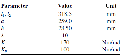
This section investigates the design of an active control to attenuate the undesired oscillations caused by flexible links. The proposed control is formed by a pose loop, designed based on SMC, and an active loop, developed using a couple of PZT actuators, as seen in Figure 5. First, this work aims to assess the influence of the attachment of the PZT on the links surfaces on the trajectory tracking and oscillation amplitudes. Then, an active control is designed to investigate the response performance of two different trajectory configurations. In this first case, two input configurations are used to investigate the proposed strategy: a step in x-direction and a step in y-direction. The input in the x-direction is defined from [70 (mm), 0 (mm), −1.4 (rad)] to [0 (mm), 0 (mm), −1.4 (rad)], while the step input in the y-direction is generated following the trajectory from [0 (mm),70 (mm), −1.4 (rad)] to [0 (mm), 0 (mm), −1.4 (rad)]. Next, a diagonal configuration is established, which can be defined from [50 (mm), −50 (mm), −1.4 (rad)] to [0 (mm), 0 (mm), −1.4 (rad)]. The physical and geometric dimensions of the 3RRR and the corresponding gains from the SMC control can be expressed in Table I. Other parameters can also be defined by
 $\gamma _1=\frac {\pi }{2}$
rad,
 $\gamma _2=\frac {11\pi }{6}$
rad,
 $\gamma _3=\frac {7\pi }{6}$
rad.
Physical properties of the 3RRR and gains of the proposed control strategy.

The responses of x- and y- step inputs are exploited to investigate the tracking trajectory of the parallel manipulator. The dynamics and kinematics of the parallel manipulator 3RRR are fully coupled, i.e., all the three motors are needed to generate a motion in both the x-direction and y-direction. The results in both step input configurations yield similar responses, which allows us to assume that steps in other directions would generate a similar conclusion. Ten measure signals are collected for each proposed configuration for a robust analysis. An average signal is then calculated to represent the signal characteristics under the corresponding step input configuration and control strategy.
4.1. Effect of the PZT on the flexibility
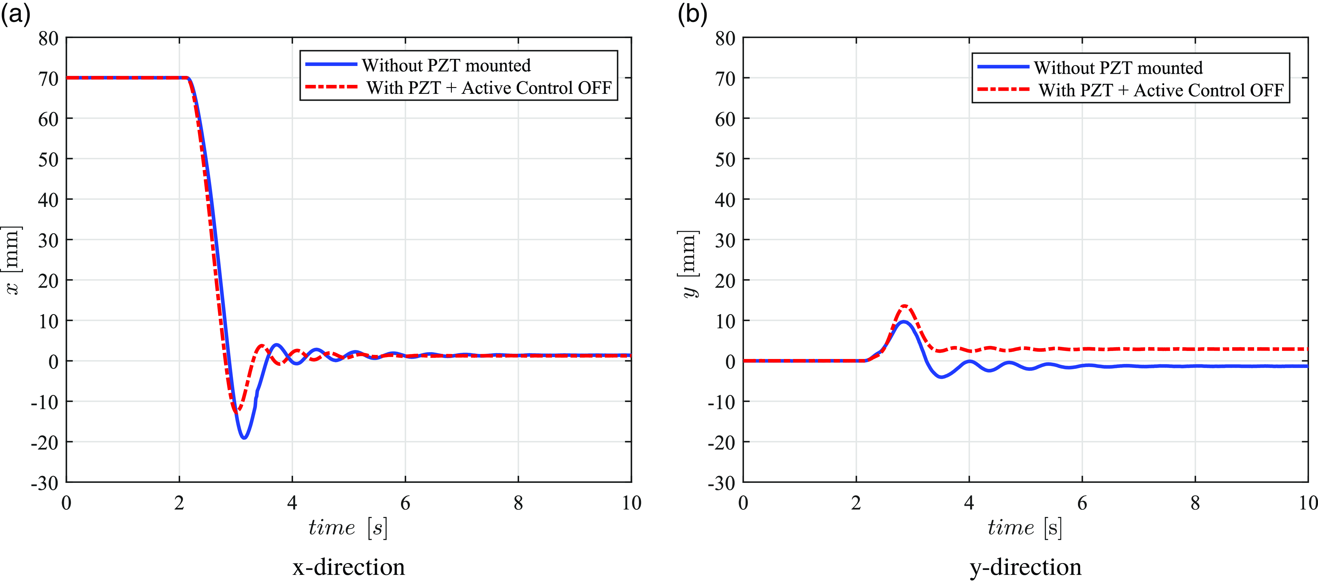
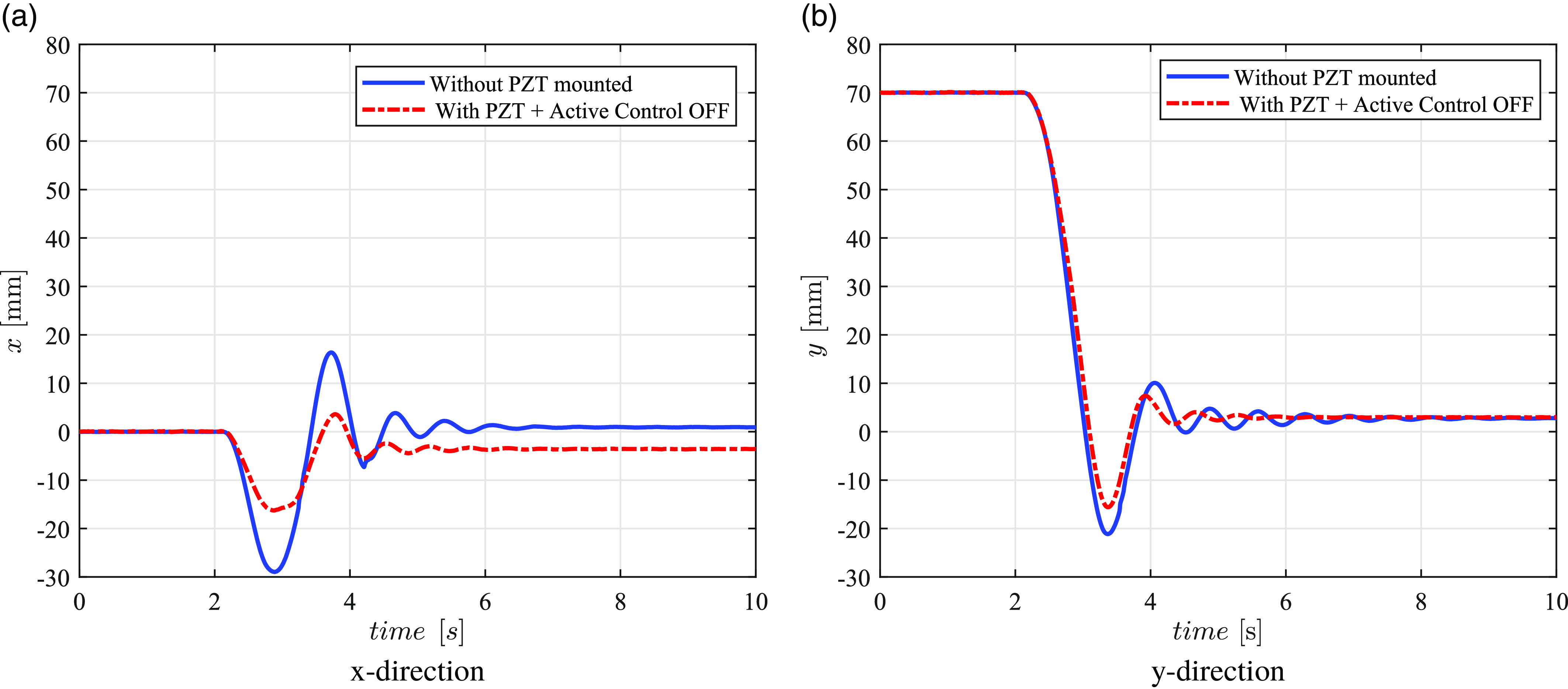
Initially, this subsection aims to investigate the impact of embedding PZT actuators in the flexibility of the manipulator’s links. This investigation is carried out by evaluating the responses acquired in two different situations: in the presence and absence of the PZT on the links surface (in this case, the active control is off). The attachment of PZT may change the dynamics and, consequently, its stiffness, providing a different response in both configurations. As mentioned, two linear independent step inputs are considered since the workspace is assumed to be Cartesian. Figure 7 depicts the responses for step input in the x-direction for both the presence and absence of the PZTs. According to the first trajectory, the presence of the PZTs on the surface enables better trajectory tracking and lower amplitudes of oscillations compared to the absence of PZTs. Regarding the maximum peaks reached by the end effector in the x-direction, there is a significant reduction from 20.00 mm to 12.82 mm, besides the lower amplitude of oscillations, as noted after the first 3.5 s. The y-direction, on the other hand, presents a slight increase in amplitude but a significant oscillation attenuation.
Step input response in x-direction.

Likewise, Figure 8 shows the x and y responses of the end effector for the step input in the y-direction. In the absence of the PZTs, the effect of links’ flexibility is more significant in both directions, as demonstrated by the overshoots. When the PZTs are embedded on both sides of the links, there is an increase in stiffness, which reduces the adverse impact on the links’ flexibility. In terms of amplitudes, note that in the x-direction, the maximum peak reached by the end effector is approximately 30.00 mm (in the absence) and 15.58 mm (in the presence of the PZTs). Similarly, in y-direction, the corresponding behavior is observed. This similar behavior in different responses leads us to conclude that other directions would also present positive attenuation characteristics.
Step input response in y-direction.

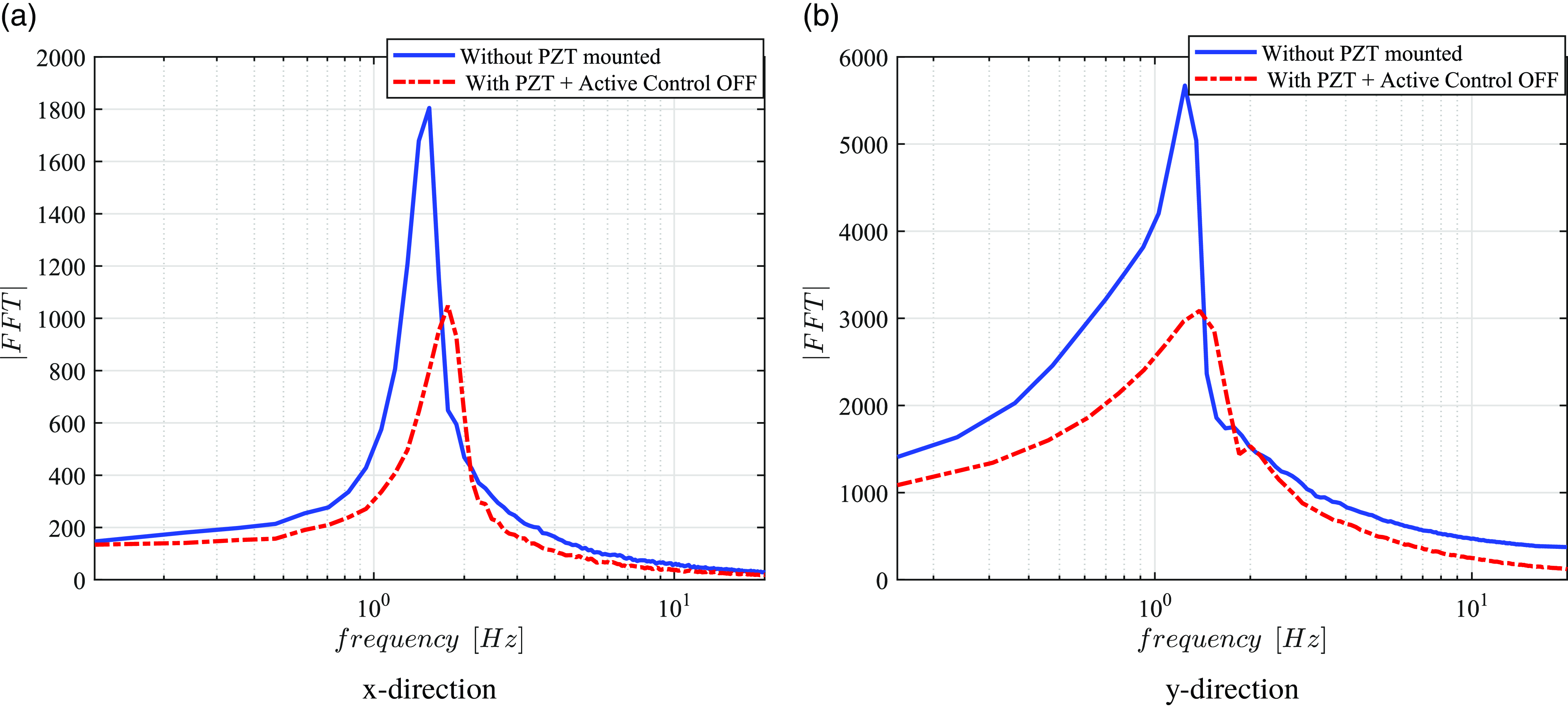
The impact of the flexibility can also be evaluated by deriving the signal spectrum with a fast Fourier transform for both the x- and y-directions, as seen in Figs. 7(a) and 8(b). This work defines the period considered to obtain the FFT after the main peak, i.e., after 3.5 s. Figure 9 shows the oscillation frequency spectrum in the step input’s corresponding directions. Note that not only are the peaks significantly reduced, showing a positive attenuation of the oscillations during the desired trajectory, but also a flattening of the frequency spectrum. It can also be observed that there is a slight change on the peaks, highlighting that the inclusion of the PZT on the links surface changes the dynamics of the parallel manipulator 3RRR.
Comparison of the output frequency spectrum considering in the presence and absence of PZT actuators.

4.2. Active control
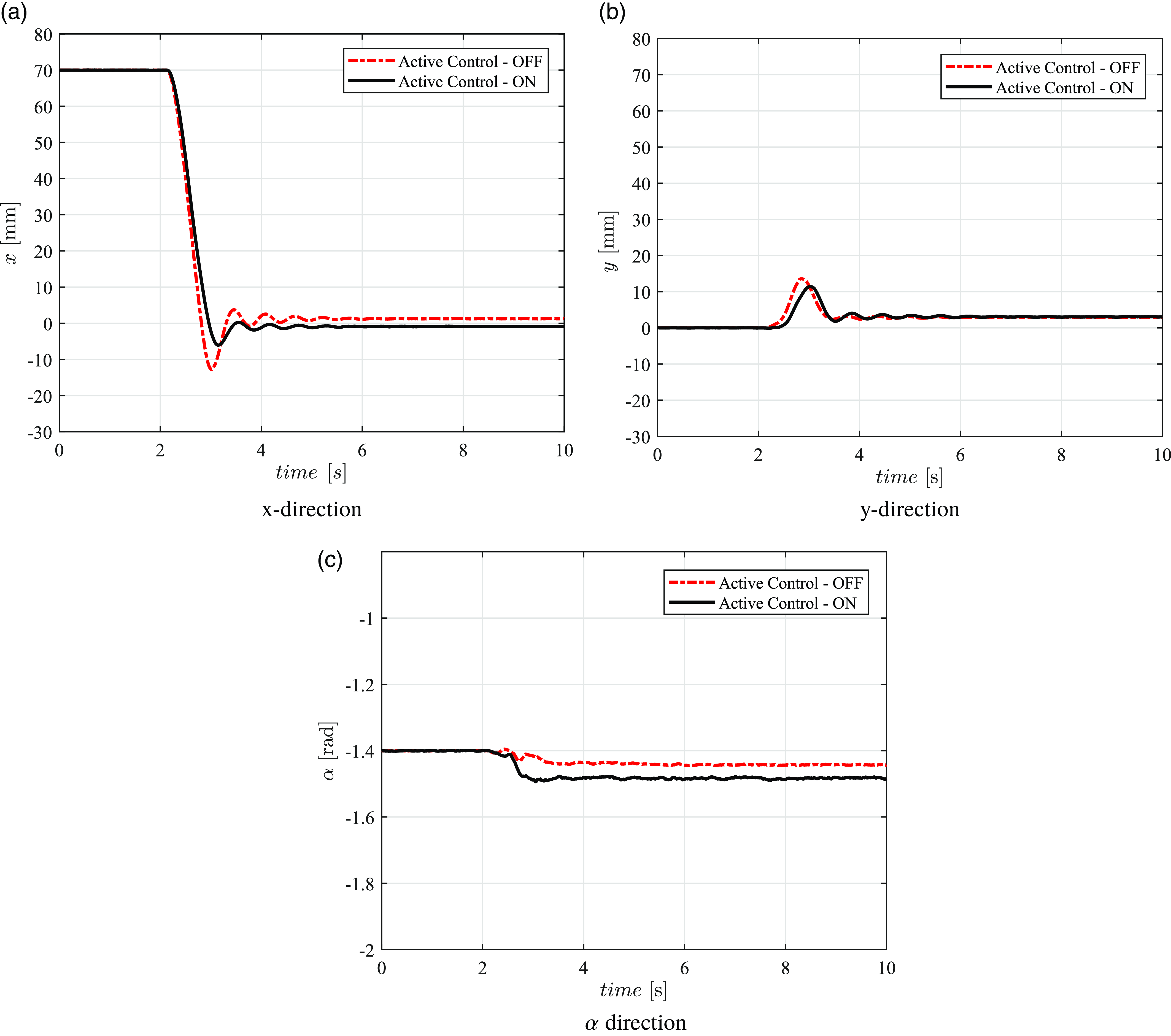
In this subsection, the active control is investigated considering both the step input response in the x and y directions. Figure 10 shows the step input response in the x-direction for both the x-, y-, and
 $\alpha$
-directions. Note that larger overshoot signals can be observed in the approach when the active control is off. For instance, an average 12.82 mm peak is observed when the active control is off, while a 6.033 mm peak is noted when the active control is on. Not only is the maximum peak reached for the end effector decreased, but the overall oscillations are also significantly attenuated over a period of time, improving the convergence and the tracking trajectory. Regarding the steady-state error, as seen in Fig 10(a), an absolute value of 1.244 mm is noted when the active control is off, whereas 0.9648 mm absolute value is obtained when the active control is on. Similarly, Figure 10(b) shows a positive attenuation of the overshoot but a slight increase of steady-state error, coming from 2.975 mm to 3.129 mm. Therefore, especially in the period of up to 7 s, the oscillations are positively reduced in the presence of active control. Figure 10(c) depicts the orientation angle (
 $\alpha$
) for both configurations. Note there is not a huge difference in terms of orientation characteristics. This slightly difference does not influence significantly on the end-effector position.
Step input response in x-direction.

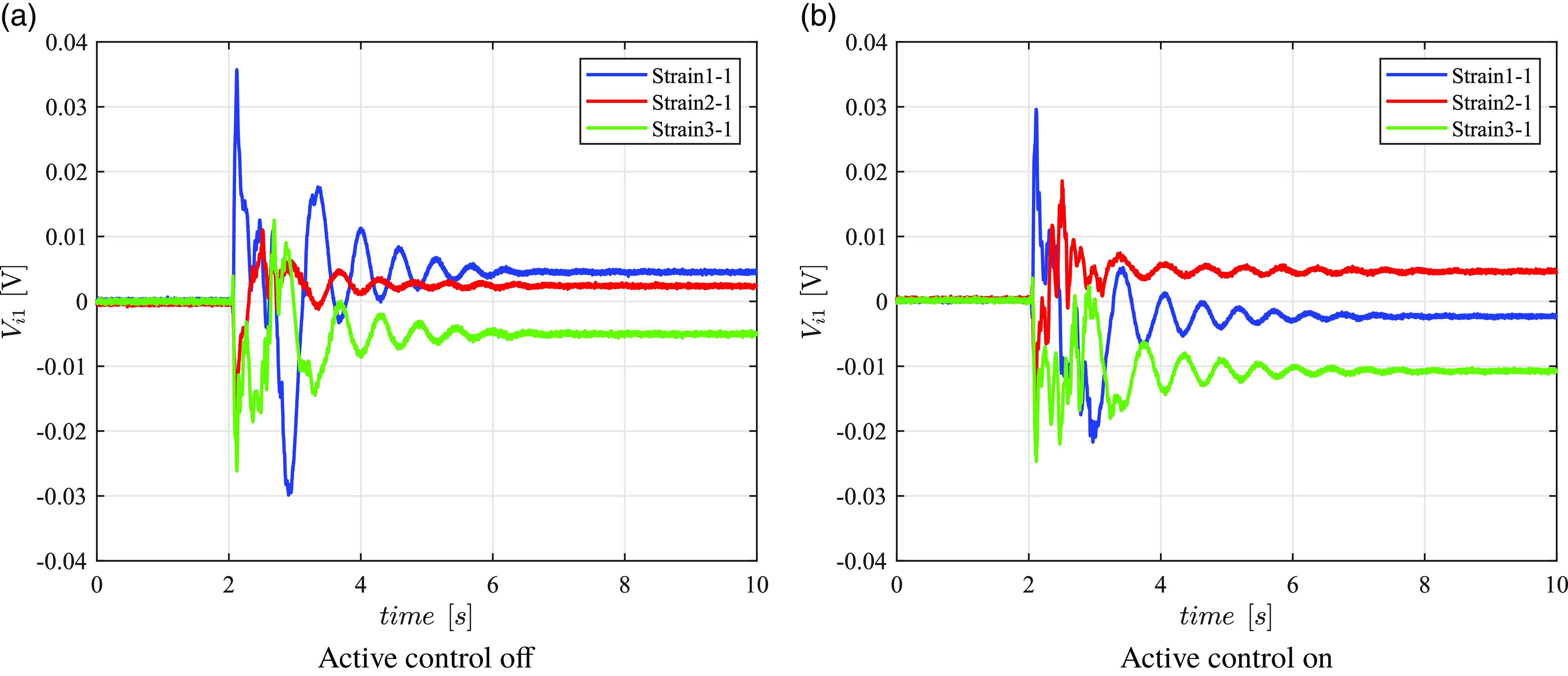
In addition, Figure 11 shows the strain signal from the strain gauges for the step input in the x-direction. The terminology “Strain i-1,” such that
 $i=1,2,3$
correspond, respectively, to each chain and link. For instance, “Strain 1-1” represents the first link of chain 1. While Figure 11(a) shows the response when the active control is off, Figure 11(b) depicts the strain signals when the active control is on. Similar to Figure 10, a slight attenuation of the maximum peaks and overshoot is observed, especially for Strain 1-1 and Strain 3-1. This decrease in maximum peaks and oscillations endorses the positive actuation of the proposed control strategy.
Strain input (
 $V_{i1}$
) for the step input response in x-direction.

Likewise, Figure 12 shows the step input response in y-direction. Note that a similar behavior can be observed in both directions. The overshoot is significantly reduced when the active control is on, and the oscillations are attenuated over the manipulator’s trajectory. In addition, there is better tracking, with lower steady-state errors in the x- and y-directions. For instance, the steady-state error for the x-direction reduced from 3.598 mm to 2.42 mm, while in the y-direction, the absolute steady-state error changed from 2.984 mm to 0.3798 mm, showing a considerable improvement in tracking and convergence of the results. Similarly to the step input in x-direction, there is a slightly difference of the
 $\alpha$
characteristics, which does not influence on the main results, from the end-effector position.
Step input response in y-direction.

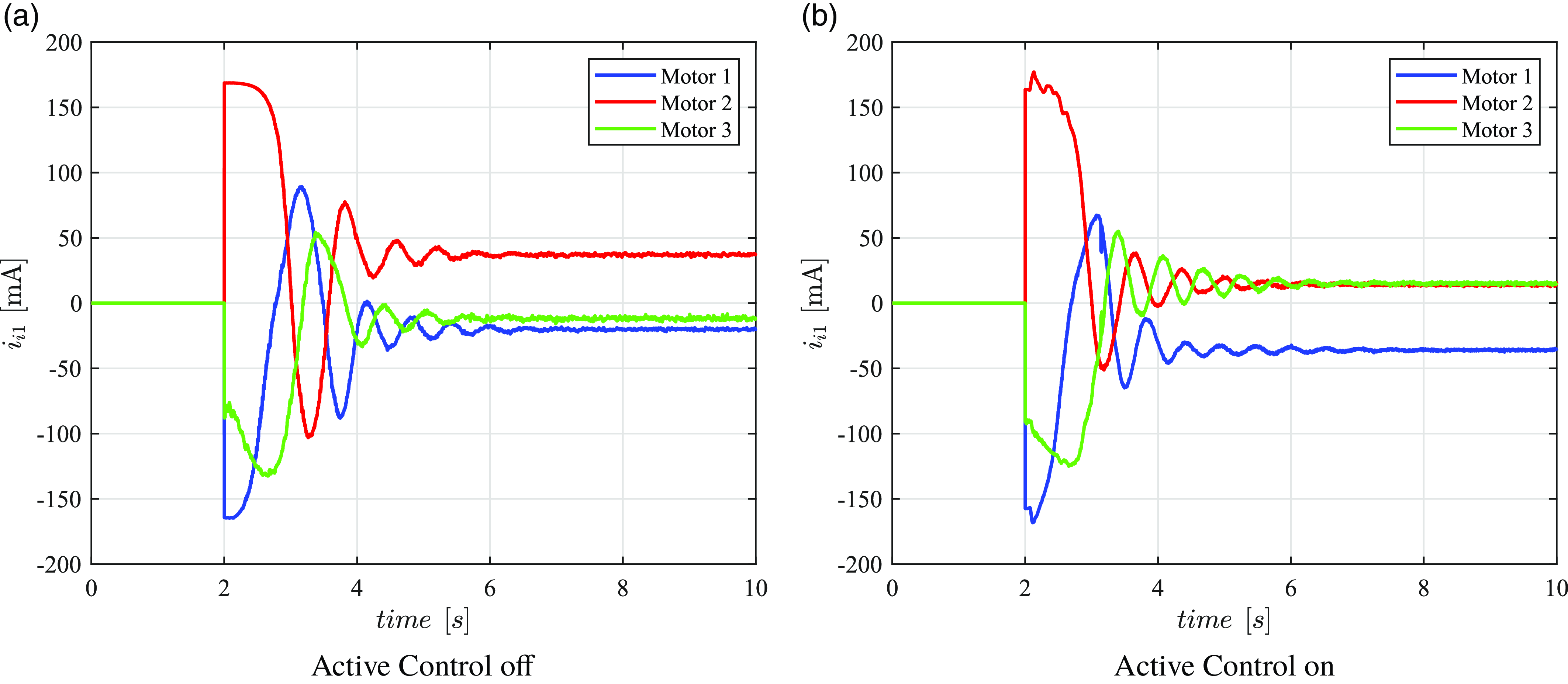
The strain input is not represented for the step input in the y-direction since they have a similar behavior of 11. In this sense, Figure 13 depicts the motor current for the step input in the y-direction, showing the corresponding control input (of the pose control loop) for the three active revolute joints. Similar to the strain input signals, the motor current also exhibited an attenuation of the maximum peaks reached by the active control strategy, with a positive attenuation of oscillations. Figure 13(a) shows the motor current when the active control is off, and Figure 13(b) depicts the motor current signals when the active control is on. This decrease in maximum peaks and oscillations endorses the positive actuation of the proposed control strategy.
Motor current for the step input in the y-direction.

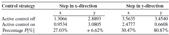
Besides visual inspection, the root mean square (RMS) technique is employed to evaluate both strategies. The RMS is chosen to investigate the oscillations over time and the steady-state error the system is subjected to. Similar to the previous case, the analyzed period of time is defined after the first main peak (after 3.5 s). The RMS is calculated by the following expression
 \begin{equation} RMS = \sqrt {\frac {1}{N} (w_1^2 + w_2^2 + \ldots + w_{N}^2)} \end{equation}
where n is the length of the corresponding vector and
 $w_1, w_2, \ldots, w_N$
are the terms related to the analyzed states (
 $x$
and
 $y$
). A percentage index is also used to compare both control strategies, which is defined by
 $P[\%] = (AC_{off}-AC_{on})/AC_{off}$
, where the terms
 $AC_{off}$
and
 $AC_{on}$
correspond to the values from the active control is off and on, respectively. Table II presents the RMS calculated for both step input directions in x- and y-directions. As a result, all the states exhibit a positive attenuation, ranging from 27.03% to 80.87%, apart from the y-direction (of step in x-direction) with a slight increase of 6.62%, mainly caused by the increase of steady-state error.
Root mean square (RMS) of the corresponding signals.

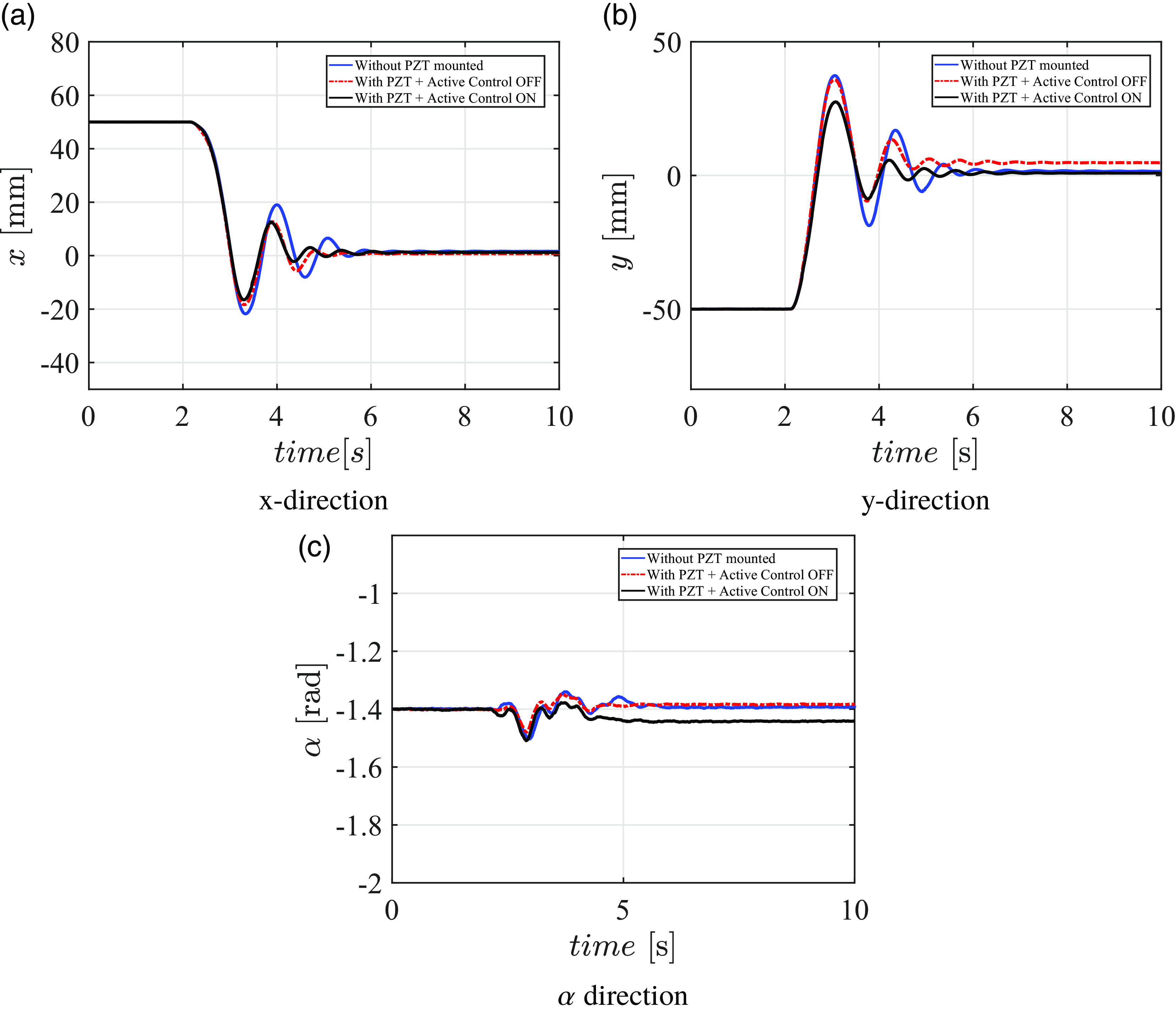
Step input response in the diagonal direction.

In addition, a second trajectory configuration is designed to investigate the proposed control strategy. In this case, a diagonal configuration is generated from [50 (mm), −50 (mm), −1.4 (rad)] to [0 (mm), 0 (mm), and −1.4 (rad)]. In contrast to the first configuration, there is a combined step response in both directions at the same time, which combines all the effects from both directions. Figure 14 shows the step input response in the diagonal direction for both the x-, y-, and
 $\alpha$
-directions. Note that larger overshoot signals can be observed in the absence of PZT. For instance, for the configuration without PZT mounted, the two main peaks are 21.72 mm and 18.99 mm in the x direction, while in the y direction, the three main peaks correspond to 37.33 mm, 18.71 mm, and 16.89 mm. On the other hand, when considering the configuration with PZT and the active control off, the main peaks in the x-direction are 18.34 mm and 12.64 mm, while in the y-direction, are defined by 35.78 mm, 9.42 mm and 13.37 mm. As observed, there is a significant reduction of the overshoots. Finally, the proposed configuration (when the active control is on) exhibits its best attenuation, with average peaks of 16.32 mm and 12.61 mm for the x-direction and 27.50 mm, 8.59 mm and 5.6 mm for the y-direction, which demonstrates a superior attenuation of the overshoots and oscillations along the desired trajectory. Ten measures from each configuration are performed to assess the control robustness and repeatability.
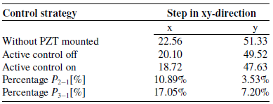
Similarly to the first case, root mean square (RMS) technique is also employed to investigate both strategies, since the oscillations and steady-state error can be assessed for both configurations. Table III presents the RMs calculated for each state in the diagonal direction. In addition, a percentage index is also used to compare the configurations with the pzt mounted (when the active control is off and on) with the configuration without the PZT mounted, respectively, defined by
 $P_{2-1}[\%]$
and
 $P_{3-1}[\%]$
. In contrast to the first trajectory configuration, more prominent peaks are observed due to the combined effects of both trajectories, which generates bigger peaks and oscillations. The more prominent effects generates a more significant values of RMS for both x- and y-directions. According to Table III, the analyzed states exhibit a positive reduction, ranging from 3.53% to 17.05%. Therefore, the use of active control shows a promising alternative to attenuate the oscillations and peaks over the two proposed trajectories.
4.2.1 Uncertainty analysis
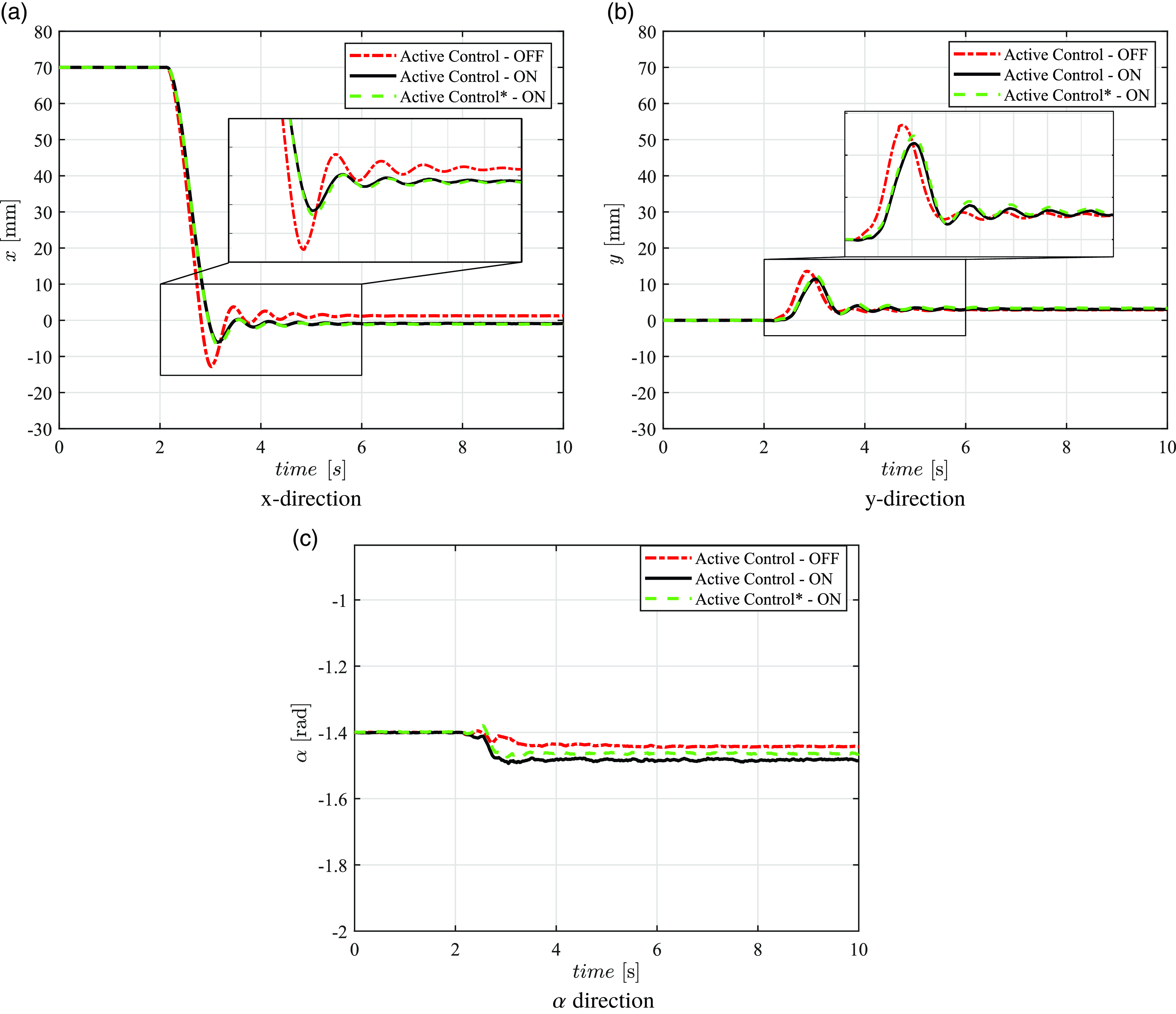
Besides the previous investigation, an additional mass, weighting 7.9 g, is attached below of the under end-effector surface, to assess its influence on the dynamic characteristics. This additional mass is included on the end-effector surface to act as an uncertainty parameter, since it is not take in account for the control design, and investigate the robustness of the proposed strategy. Note that since both step input responses in x- and y-directions provide similar behavior, the step response in x-direction is chosen to be represented in this subsection. Ten measures are carried out to obtain the mean signal of each proposed configuration. Figure 15 depicts the step input response in the x-direction, in the presence of additional mass, for both the x-, y-, and
 $\alpha$
-directions.
Root mean square (RMS) of the corresponding signals.

The nomenclature employed for the active control distinguishes between the presence and absence of uncertainty, i.e., the additional mass. Note that there is an asterisk on the second active control symbolizing the presence of additional mass on the end effector. As observed in subsection 4.2, larger overshoot signals are observed when the active control is off. Even in the presence of an additional mass, the maximum peak is attenuated. For instance, an average 12.82 mm peak is noted when the active control is off, while a 6.033 mm and 6.403 mm peak are observed when the active control is on, in the absence and presence of mass, respectively. The inclusion of the extra mass increases the uncertainties on the dynamic system, slowing its response and accuracy. Similarly, Figure 15(b) shows a positive reduction of the overshoot, with a maximum peak of 13.55 mm when the active control is off, and 11.415 mm and 12.296 mm when the active control is on, respectively, in the absence and presence of the additional mass. Therefore, even in the presence of additional mass on the end-effector surface, the oscillations are positively reduced and the peaks are significantly minimized.
Step input response in the x-direction in the presence of additional mass.

5. Final remarks
Over the last few years, PMs have emerged as a promising alternative due to their structural and performance advantages, including energy efficiency and dynamic response. The PMs with flexible links exhibit better characteristics than those with rigid links, such as they demand low energy, less mass, and generally present higher working velocities. On the other hand, due to their lightweight design, these systems have prominent flexibility, yielding undesired deformations and vibrations, decreasing the tracking trajectory and overall control performance.
In this sense, researchers have investigated different control strategies to improve the end-effector’s control performance, stability, and tracking trajectory. This manuscript proposes the design of an active vibration control for 3RRR prototype with flexible links. The control strategy comprises two loops: a pose control, based on SMC, and active control. While in the pose loop, an oCam-5CRO-U camera is used to collect the images over the desired trajectory, the active control uses the combination of strain gauges and PZT actuators to attenuate the undesired vibration of flexible links. Digital filters are also employed to remove the DC and noise of the signal acquired from the strain gauges, which are then used to obtain the corresponding control of the PZT actuators.
The experiment is performed using two stages: the evaluation of the 3 RRR dynamics in the presence and absence of the PZT actuators on the link’s surface and the performance of the active control on the tracking trajectory. Two trajectory configurations are designed to investigate the control strategy. A step input in the x-direction generates a trajectory from [70 (mm), 0 (mm), −1.4 (rad)] to [0 (mm), 0 (mm), −1.4 (rad)], while the step input in the y-direction comprises the trajectory from [0 (mm),70 (mm), −1.4 (rad)] to [0 (mm), 0 (mm), −1.4 (rad)]. On the other hand, for the diagonal configuration, the motion is generated from [50 (mm), −50 (mm), −1.4 (rad)] to [0 (mm), 0 (mm), −1.4 (rad)]. The planar parallel manipulator in the Cartesian workspace allows us to affirm that since the results in the x- and y-directions yield similar characteristics, steps in other directions would lead to a similar conclusion. In addition, ten measures from each configuration are performed to endorse the control robustness and repeatability.
Initially, the impact of the attachment of PZTs on the link’s surface is assessed. Note that the effect of flexibility, in the absence of the PZTs, is more significant in both directions, showing more prominent overshoot and longer oscillations. When the PZTs are attached on both sides of the links, there is an increase in stiffness, which reduces the adverse impact of thinner links. In terms of amplitude, there is an average attenuation of 50% on the maximum peaks in the corresponding directions of the step input response. Two trajectory configurations are investigated to investigate the proposed strategy performance. Then, the active control is also investigated, considering different configurations of step input response in the x- and y-directions, even in the presence of additional mass on the surface of the end effector. The results reveal that not only is the maximum peak significantly attenuated, but the overall oscillations are also positively reduced along the time period, improving the convergence and tracking trajectory. When analyzing the strain input signals and motor currents, there is an interesting attenuation of the overshoot and oscillations, endorsing the efficiency of the proposed strategy. RMS metric is also employed to quantify the attenuation, showing an average reduction of 30% in the corresponding step input directions. Therefore, an active control loop improves the tracking trajectory with lower oscillations, enhancing the system’s performance.
The recommendations for future works include to perform a different set-up experimental analysis to evaluate the controller performance, including the additional of different masses on the end effector and different trajectory configurations.
Author contributions
Conceptualization, RSG, GCO, GKR, and MMS; methodology, RSG, GCO, and GKR; project administration, RSG and MMS; writing—original draft, RSG; writing—review and editing, RSG, GCO, GKR, and MMS. All authors have read and agreed to the published version of the manuscript.
Financial support
This work was supported by the São Paulo Research Foundation – FAPESP [grant numbers 18/21336-0, 22/06816-1, 23/00687-8, and 23/07834-6] and the National Council for Scientific and Technological Development – CNPq [grant number 303884/2021-5].
Conflicts of interest
The authors declared no potential conflicts of interest with respect to the research, authorship, and/or publication of this paper.
Ethical approval
Not applicable.