



Introduction
In order to improve the communication quality and increase the channel capacity in modern communication systems, multiple-input multiple-output (MIMO) technology is one of efficient and essential methods [Reference Jensen and Wallace1]. In MIMO technology, highly isolated multiple transmitting and receiving antennas are employed. Several techniques are used to obtain high isolation among the different ports of antennas. Decoupling methods, neutralization line methods, polarization, and pattern diversities are name a few [Reference Sharawi2]. Owing to various inherent advantages such as low loss, good inter-port isolation, low profile, and ease of integration with planar circuits, substrate-integrated waveguide (SIW) technology is gaining much more attention from the researchers nowadays [Reference Bozzi, Georgiadis and Wu3]. Several 2-port and 4-port MIMO antennas [Reference Niu and Cao4–Reference Wei, Liu, Wan and Liu7] based on SIW technologies are reported in the literature. A full-mode SIW (FMSIW) cavity backed slot MIMO antennas utilizing TE110 mode for lower WLAN band (2.4 GHz) is presented in papers [Reference Zhai, Chen and Qing5, Reference Zhai, Chen and Qing6]. To design the compact antenna systems, several miniatured versions of SIW such as half-mode SIW (HMSIW), quarter-mode SIW (QMSIW), eighth-mode SIW (EMSIW) are also reported [Reference Wei, Liu, Wan and Liu7–Reference Deng and Lv9]. In paper [Reference Nandi and Mohan8], 2-port and 4-port EMSIW-based MIMO antennas are presented. Several 8-port MIMO antennas for 5 G communication systems have been reported in the literature [Reference Deng and Lv9–Reference Zhao and Ren15]. In paper [Reference Deng and Lv9], an 8-port MIMO antenna with tightly coupled pairs for 5G applications is presented, while in paper [Reference Parchin10], dual-polarized MIMO slot antenna system is designed and developed. Eight-element MIMO antenna arrays for sub-6 GHz is presented in papers [Reference Morsy11,Reference Sharawi12]. In paper [Reference Mishra, Chaudhuri, Kshetrimayum, Sharawi and Kishk13], a 5-GHz eight-element-based MIMO antenna system for IEEE 802.11ac devices is presented. Recently, an 8-port π/8 SIW cavity-based MIMO antenna for 6.1 GHz is demonstrated that utilizes TE220 mode of the rectangular SIW cavity [Reference Al-Hadi, Ilvonen, Valkonen and Viikari14]. Due to the usage of higher order mode, the overall size of the antenna is increased. Thus, designing a compact 8-port MIMO antenna with good isolation among the ports is a great challenge.
In this paper, an 8-port MIMO antenna based on EMSIW cavities for sub-6 GHz communication systems is presented. The open-ended region of EMSIW cavity resonator and the edges of the slots help in the excitation of TE110 mode. High isolation among the EMSIW resonator is due to the strategic placement of diagonal slots and vias. The detailed working mechanism of the proposed MIMO antenna is also demonstrated.
Antenna configuration
Figure 1 represents top view of the proposed miniaturized 8-port EMSIW MIMO antenna. The designed antenna comprises eight EMSIW cavities which are individually excited through eight inset-fed 50-Ω microstrip feedlines. The EMSIW MIMO antenna is designed on RT/Duroid 5880 substrate (ε r = 2.2, h = 0.508 mm, tanδ = 0.0004).
Geometrical sonfiguration of proposed 8-port EMSIW MIMO antenna [L = 60, w = 60, lf1 = 5, lf2 = 5.5, wf = 1.45, s = 0.7, s1 = 0.5, a1 = 9, b1 = 2, a2 = 8, b2 = 4, a = 24, px = 5, p = 2, d = 1 (all are in mm).].

Unit element of the MIMO antenna
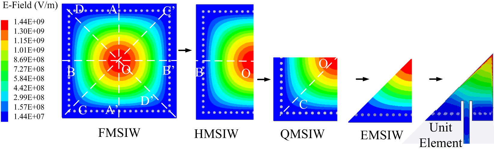
Figure 2 shows the evolution of the unit element of the proposed MIMO antenna. In FMSIW cavity resonator, the TE110 mode is the dominant mode, in which there is one half wavelength variation along the x-axis, one half wavelength variation along the y-axis and no variation of the fields along the z-axis. These electric fields are symmetrical along the plane AA’. The FMSIW cavity resonator can be bifurcated through the magnetic wall concept along the symmetrical plane to obtain the HMSIW cavity resonator. The HMSIW cavity resonator can be further bifurcated along the symmetrical plane BO to obtain QMSIW cavity resonator. These bifurcations not only preserve the modal characteristics of TE110 mode, with maximum intensity of fields at the open-ended edges, but also facilities the size miniaturization. The QMSIW cavity resonator is further bifurcated along symmetrical plane CO to obtain an EMSIW cavity resonator. As can be visualized from the figure, the maximum intensity of fields at the open-ended edges is observed which ensures the preservation of the modal characteristics of TE110 mode. The EMSIW cavity resonator is inset-fed by a microstrip feedline. It can be visualized from the electric field distribution; this structure also supports TE110 mode with maximum intensity of fields at the open-ended edges. Thus, it is seen that from the evolution of the unit element that it supports TE110 mode with maximum intensity at the open-ended edges.
Evolution of the unit element of the proposed MIMO antenna.
Design stages of the proposed MIMO antenna
In this subsection, the design stages of the proposed EMSIW MIMO antenna is demonstrated in Fig. 3. Stage-I consists of eight EMSIW cavities placed side by side sharing the open-ended side walls as depicted in Fig. 3(a). Each of the EMSIW cavities is inset-fed through a microstrip feedline. The MIMO antenna in Stage-I radiates at 3.50 GHz with a mutual coupling between the Port P1 and Port P2 (|S21| = −12.5 dB). While the mutual coupling between the others ports are below −15 dB. It can be also verified by illustrating its electric field distributions.
Different stages of proposed 8-port EMSIW MIMO antenna. (a) Stage-I, (b) Stage-II, (c) Stage-III, (d) Stage-IV.
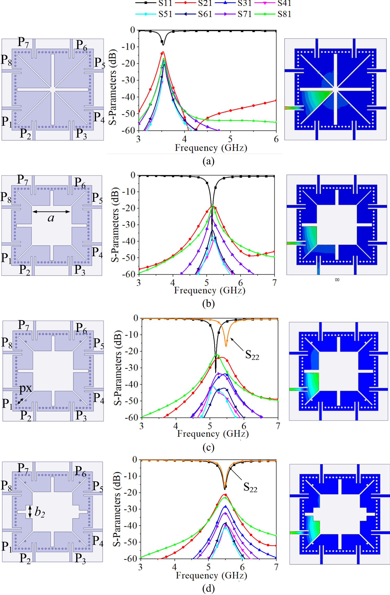
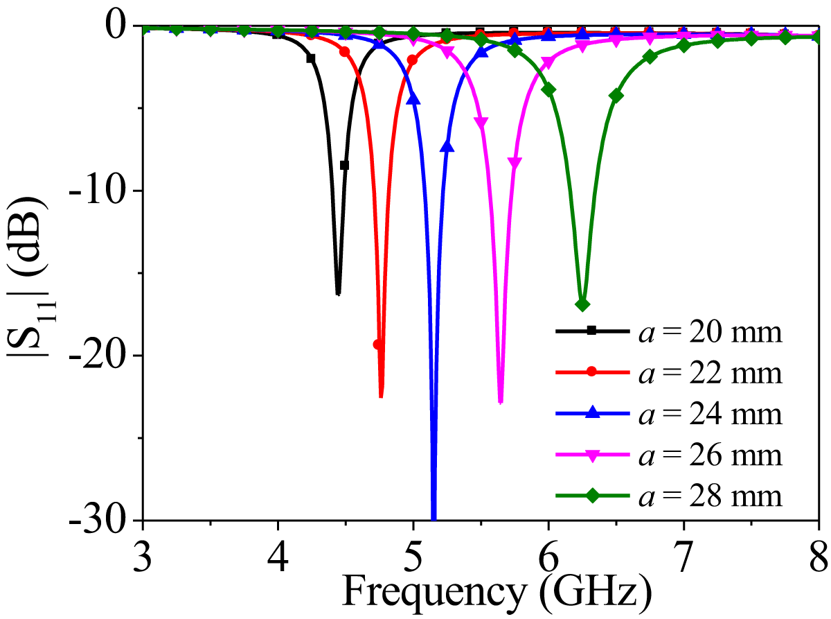
Further to enhance the isolation, a square slot of dimensions a × a is introduced at the center of the EMSIW MIMO antenna [Fig. 3(b)]. This square slot not only improves the impedance matching but also introduces extra capacitance that in turn shifts the operating frequency of MIMO antenna to 5.2 GHz. The isolation among all the ports is improved and it is better than 18.5 dB. In order to observe the effect of square slot on the operating frequency, a parametric study is performed on the design parameter a. Figure 4 shows the S-parameters of the MIMO antenna in Stage-II for the different values of a. It is clear from the figure that as that value of a increases the operating frequency of the MIMO antenna in Stage-II shifts to higher value.
Parametric analysis for the design parameter a in stage-ii.
For satisfactory MIMO operation, the mutual coupling among all the ports should be less than 20 dB [Reference Sharawi2]. The MIMO antenna in Stage-III is obtained with the introduction of four vias of diameter d in second, third, sixth and seventh EMSIW cavities [Fig. 3(c)]. These vias shifts the resonant frequencies of corresponding second, third, sixth and seventh EMSIW cavities to higher value of 5.5 GHz, while the resonant frequencies of first, fourth, fifth and eighth EMSIW cavities remain unaltered at 5.2 GHz. The isolation is better than 20 dB among all the ports of the MIMO antenna in Stage-III.
To design a MIMO antenna at 5.5 GHz, i.e. for sub-6 GHz communication systems, all the antenna elements must radiate at the same frequency. To increase the operating frequencies of first, fourth, fifth, and eighth EMSIW cavities, a pair of short square slots are engraved between them [Fig. 3(d)]. These short square slots increase the operating frequencies of first, fourth, fifth and eighth EMSIW cavities to 5.5 GHz. The asymmetrical structure not only facilitates the radiation of all the ports of designed MIMO antenna at 5.5 GHz but also enables the high inter-port isolation. The inter-port isolation of the proposed 8-port EMSIW MIMO antenna is better than 22 dB.
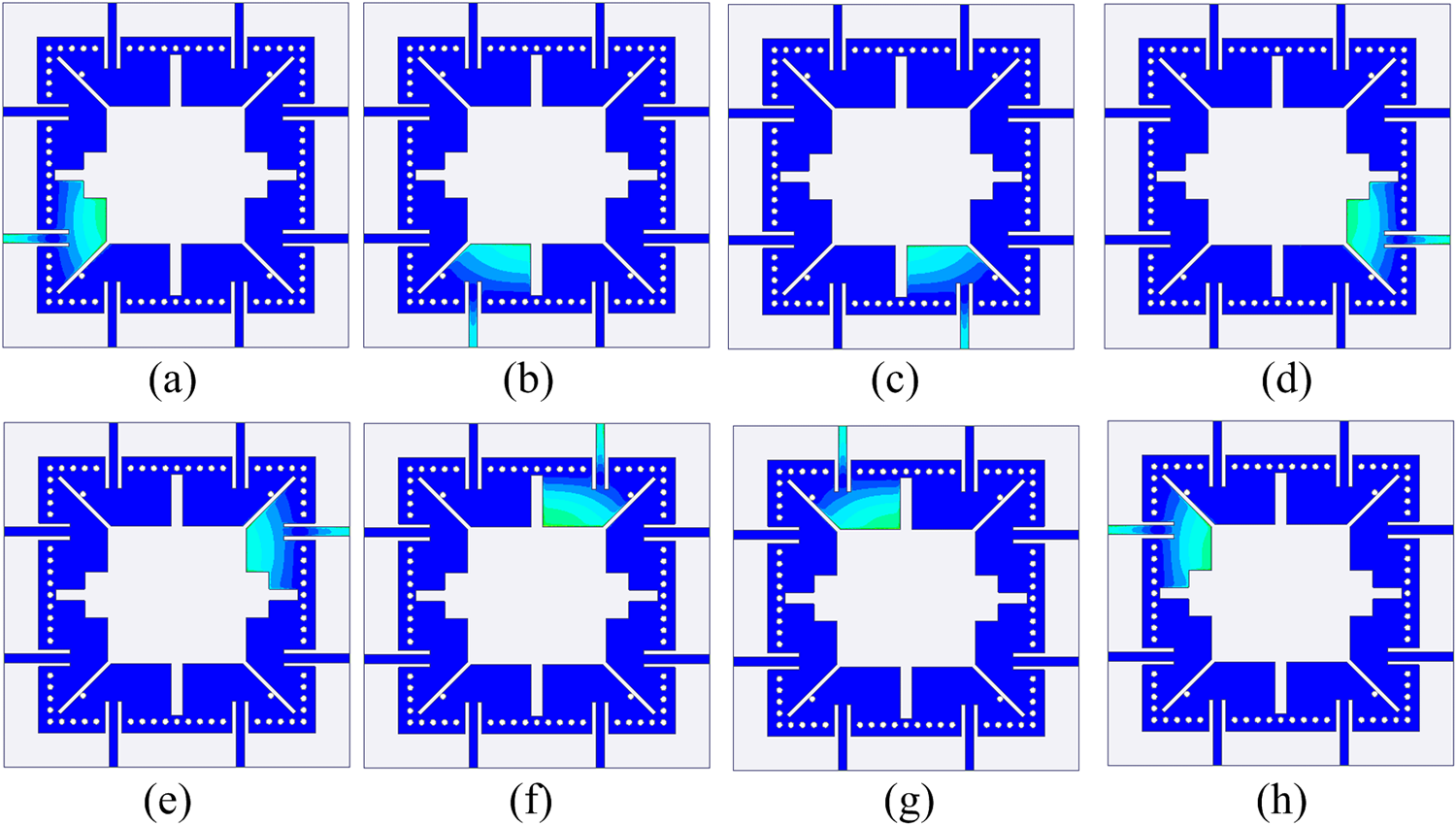
Figure 5 shows the electric field distribution of the designed MIMO antenna with each port excitations. During the excitation of the respective port, the remaining ports are terminated with 50 Ω matched loads. It is clear from the figure that all the EMSIW resonators have field configuration similar to dominant TE110 mode. Also, when one of the ports is excited, negligible fields are present on the other resonators which guarantee high inter-port isolation.
Electric field distribution at (a) P1 ON, (b) P2 ON, (c) P3 ON, (d) P4 ON, (e) P5 ON, (f) P6 ON, (g) P7 ON, and (h) P8 ON.
Experimental results
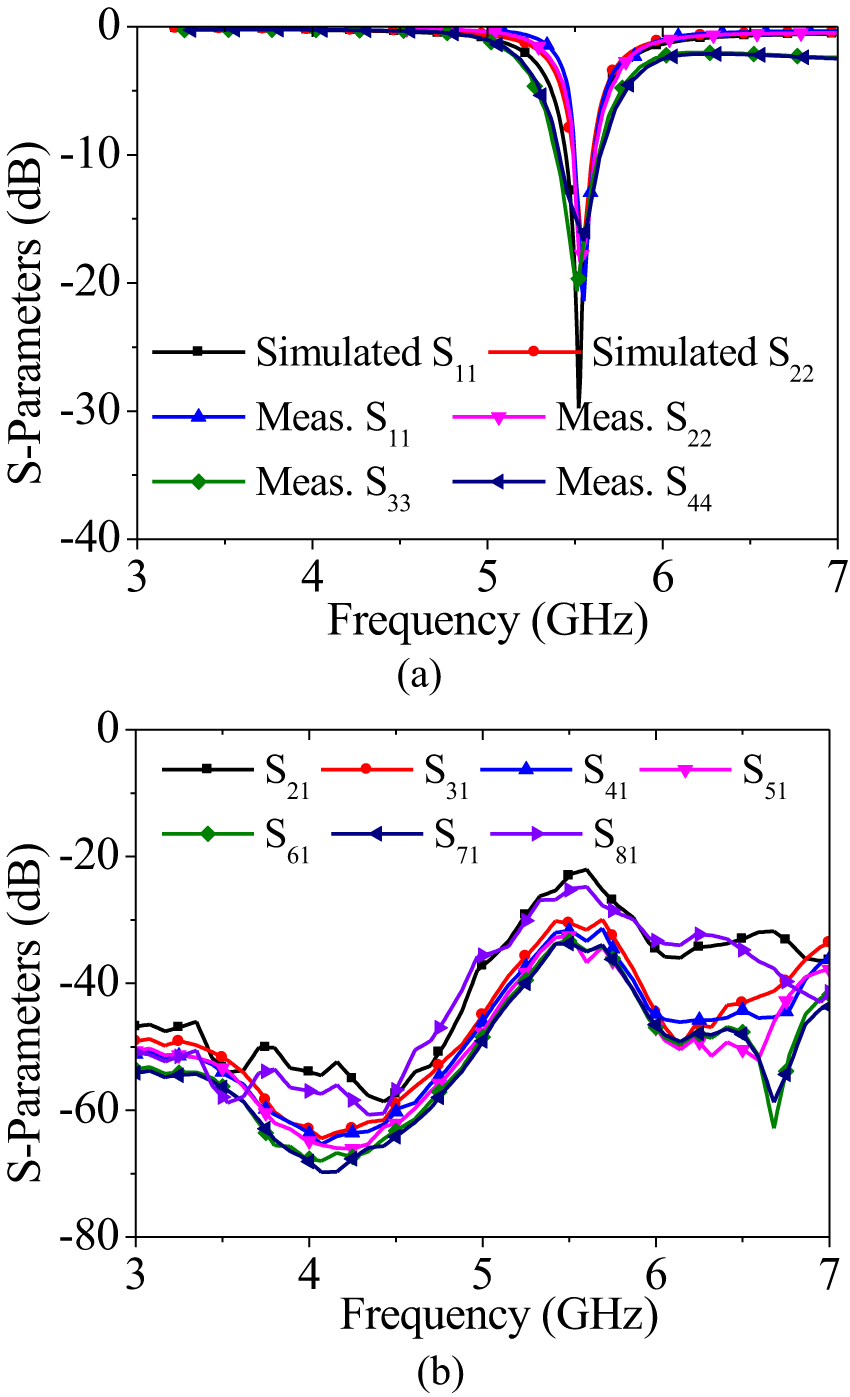
To demonstrate the effectiveness of present design approach, a prototype of the designed 8-port EMSIW MIMO antenna is fabricated using standard Printed Circuit Board fabrication techniques and Sub-Miniature Version A connectors are connected for measurement purposes. Figure 6 shows the top and bottom views of the fabricated prototype. The overall dimensions of the designed MIMO antenna is 1.1λ0 × 1.1λ0 × 0.009λ0, where λ0 is the free space wavelength at the operating frequency. The S-parameters are measured using Agilent E5071C VNA. Figure 7(a) shows the simulated and measured |S11| of the designed MIMO antenna. The simulated impedance bandwidth is 180 MHz while the measured impedance bandwidth is 220 MHz. The isolation between the ports of the antenna element is plotted in Fig. 7(b). The isolation between the ports is better than 22 dB in all the cases, that is good enough for MIMO applications.
Photograph of fabricated prototype. (a) Top view and (b) Bottom view.

S-parameters of proposed 8-port EMSIW MIMO antenna. (a) Simulated S11, S22 and measured S11, S22, S33, S44 parameters and (b) measured S21, S31, S41, S51, S61, S71 parameters.
For the designed MIMO antenna, under the individual excitations of ports P1 and P2, ϕ = 45° is the E-plane and ϕ = 135° is the H-plane. Whereas, under the individual excitations of ports P3 and P4, ϕ = 135° is the E-plane and ϕ = 45° is the H-plane. The simulated and measured radiation patterns for xz- and yz- planes of the designed MIMO antenna at its operating frequency is plotted in Fig. 8. For brevity, only the radiation pattern of first four ports are shown in this paper. The x-pol levels are better than 15 dB in all the cases in the broadside direction. High cross-polarization is observed because of the different directions of the two open sides of the EMSIW resonators and its asymmetric excitation.
xz- and yz-plane radiation patterns under (a) P1 ON, (b) P2 ON, (c) P3 ON, and (d) P4 ON. Other ports are terminated with 50 Ω matched loads excitation.

Figure 9 shows the peak realized gain and radiation efficiency of the proposed MIMO antenna. The peak gain of the designed antenna is approximately 4.62 dBi, while the radiation efficiencies are above 80%.
Peak realized gain and radiation efficiency of the proposed MIMO antenna.

The MIMO performance of the designed antenna is evaluated in terms of envelope correlation coefficients (ECC) and channel capacity loss (CCL). Figures 10 and 11 show the ECC and CCL of the proposed MIMO antenna, respectively. The ECC and CCL of the MIMO antenna are within the acceptable limits of 0.5 and 0.4 bits/Hz/s, respectively.
Envelope correlation coefficient (ECC) of the proposed MIMO antenna.

Channel capacity loss (CCL) of the proposed MIMO antenna.

To ensure the potential candidacy of the designed MIMO antenna, a comparison with the existing 8-port MIMO antennas in terms of size, isolation, gain, and MIMO performance is presented in Table 1. As compared to the other reported 8-port MIMO antennas, the novel features of the proposed MIMO antenna are as follows: (i) To the best of authors’ knowledge, this is the first instance where EMSIW cavity resonator-based MIMO antenna is reported. Moreover, π/8 partial SIW is the only 8-port SIW-based MIMO antenna [Reference Mishra, Chaudhuri, Kshetrimayum, Sharawi and Kishk13] is reported. However, the proposed MIMO antenna has compact dimension, better gain, better isolation, and more bandwidth compared to [Reference Mishra, Chaudhuri, Kshetrimayum, Sharawi and Kishk13]. (ii) Moreover, the proposed EMSIW MIMO antenna, in comparison to papers [Reference Sharawi12–Reference Zhao and Ren15], has the flexibility to redesign it for any frequency that lies between 4.4–6.4 GHz without changing its overall dimensions. (iii) In spite of using miniaturized version of FMSIW, i.e. EMSIW resonator, good isolation among the closely placed antenna elements is obtained.
Comparison with other 8-port MIMO antennas

Note: λ0 is the wavelength at the operating frequency. NM = not mentioned.
Conclusion
In this paper, an 8-port MIMO antenna for sub-6 GHz communication systems is presented. The compactness of the MIMO antenna can be attributed toward the usage of miniaturized EMSIW cavity as an antenna element. The asymmetricity in the antenna structure is responsible for good isolation among all the ports of the antenna elements without affecting its impedance bandwidth. The designed MIMO antenna has an impedance bandwidth of 180 MHz, 22 dB inter-port isolation, 4.62 dBi peak gain, and excellent MIMO performance which makes it a suitable candidate for sub-6 GHz communication systems.
Competing interests
The authors declare that they have no competing financial interests or personal relationships that could have appeared to influence the work reported in this paper.

Dr. Gunjan Srivastava received her Ph.D. degree from the Indian Institute of Technology (Indian School of Mines), Dhanbad, India, in Microwave Engineering in 2016. At present, she is working as Associate Professor in the Department of Electronics and Communication Engineering at Graphic Era (Deemed to be) University, Dehradun. Earlier, she was associated with Department of E&ECE at Indian Institute of Technology Kharagpur as a capacity of Women Scientist. She has authored or co-authored over 14 peer-reviewed international journal and conference papers. Her main research interests are design of ultra-wideband, reconfigurable, SIW, MIMO, and self-multiplexing antennas.

Vimal Kumar was born in Bihar, India, on January 13, 1994. He received his B.Tech degree specializing in Electronics and Communication Engineering from Muzaffarpur Institute of Technology Muzaffarpur, India, in the year 2017 and his M.Tech degree from the Department of Avionics, Indian Institute of Space Science and Technology Thiruvananthapuram, India, in the year 2019. Currently, he is pursuing a Ph.D. from the Department of Electronics and Communication Engineering, Indian Institute of Technology Roorkee, India. Mr. Kumar has authored and co-authored 1 journal and 12 conference papers. His research interests are space-fed high-gain antennas, MIMO antennae, and passive microwave circuits.

Dr. Akhilesh Mohan received the B.Tech. degree in Electronics Engineering from Kamla Nehru Institute of Technology, Sultanpur, India, in 2002, the M.Tech. degree and Ph.D. degree in Microwave Engineering from Indian Institute of Technology Kanpur, Uttar Pradesh, India, in 2004 and 2009, respectively. From 2009 to 2010, he worked as a Scientist at Space Applications Center, Indian Space Research Organization, Ahmedabad, India. From 2010 to 2013, he was a faculty member with the Department of Electrical Engineering at Indian Institute of Technology Jodhpur, Rajasthan, India. From 2013 to 2020, he was a faculty member with the Department of Electronics and Electrical Communication Engineering at Indian Institute of Technology Kharagpur, West Bengal, India. Since 2021, he has been a faculty member with the Department of Electronics and Communication Engineering at Indian Institute of Technology Roorkee, Uttarakhand, India. Dr. Mohan has authored and co-authored more than 150 peer reviewed international journals and conference papers. His research interests include the design of microwave filters, antennas, and absorbers for wireless communication systems.



