
Introduction
The use of aluminum alloys has been considerably increased in automotive structural applications due to the fact that they have low density, good formability, and high strength. Bending is also highly important in the shaping of parts of great complexity. Several experimental studies have been conducted so as to examine the influence of alloy composition on the behavior of 6000 series alloy sheets under bending conditions.[Reference Asano, Minoda and Yoshida1–Reference Hirth, Marshall, Court and Lloyd4]
The damage incurred in the process of bending tends to be attributed to developing surface roughness as well as to intense strain localization, with shear bands being initiated at sites of strain concentration due to variable initial thickness.[Reference Lloyd, Gupta, Chandra and Sakai5–Reference Kuroda and Tvergaard9]
In all cases, the manufacturing of aluminum panels of optimal strength for use in the automotive industry depends on the chemical composition of the relevant alloys in conjunction with thermomechanical processes.[Reference Lloyd, Gupta, Chandra and Sakai5, Reference Miller, Zhuang, Bottema, Wittebrood, De Smet, Haszler and Vieregge6] Davidkov et al.[Reference Davidkov, Petrov, De Smet, Schepers and Kestens10] studied the importance of Mg2Si and AlCuMgSi Q-phase particles in the bending behavior of the 6016 series aluminum alloy. They found that bendability decreased as copper, iron, and silicon content increased. Other studies have also examined the way in which thermal softening affects shear banding.[Reference Batra and Liu11, Reference Batra and Wei12]
Nickel has been widely employed in the production of coatings designed to ameliorate the surface characteristics of Al alloys for use in microelectronic devices.[Reference Molina, Saravanan, Narciso and Louis13–Reference Li, An and Wu19] Nickel deposition can be achieved by electrolytic (galvanostatic as well as potentiostatic) and electroless techniques on zincate-coated aluminum alloys.[Reference Molina, Saravanan, Narciso and Louis13–Reference Maozhong An and Wu15, Reference Abdel, Shaaban and Abdel Hamid17, Reference Joshi and Ramesh20–Reference Panagopoulos, Georgiou, Tsopani and Piperi22]
The present study focuses on the correlation between bendability and the microstructure of uncoated and Ni-coated AI6156 sheets at different strain rates. For the nickel coating on the Al alloy, a zincate was pre-placed on the alloy. However, various phenomena such as delamination, crack initiation, and propagation[Reference Panagopoulos, Gergiou, Agathocleous and Giannakopoulos23–Reference Slamecka, Pokluda, Kianicova, Hornikova and Obrtlik26] were detected in the tensile region of bended Ni-coated aluminum.
Materials and method
The substrate material used was a 6156-T61 commercially pure and aged wrought aluminum alloy sheet, whose wt.% chemical composition was as follows: 95.2% Al, 3.5% Mg , 0.5% Mn , 0.3% Si, 0.26% Cr, 0.24% Fe, with a hardness value of 130 HVN, from which sheet parallelepiped specimens of 11 cm × 1 cm × 0.2 cm were cut.
All aluminum alloy specimens underwent SiC mechanical polishing, after which, with the aid of a Mahr Perthen Profilometer, measurements were taken of their average roughness Rα, which was found to be approximately 0.3 µm. Stress relieving of the samples was achieved by annealing them at 200 °C for a period of 2 h in an argon atmosphere furnace.
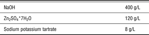
The aluminum surfaces underwent a zincate pre-treatment by immersion,[Reference Takacs, Sziraki, Torok, Solyom, Gacsi and Gal-Solymos14, Reference Panagopoulos and Georgiou21, Reference Panagopoulos, Georgiou, Tsopani and Piperi22] with a view to increasing the adhesion bonding of the aluminum substrate and the Ni coating. Table I presents the chemical composition of the zincate solution that was used. The specimens were immersed for approximately 1 min at a temperature of 25 °C. The zincate coating was found to have high interfacial integrity and, on average, measured 5 µm, while the electrodeposited Ni coatings were approximately 20 µm thick.
Zincate bath chemical composition.

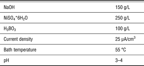
After the zincate deposition on the Al alloy substrate, the nickel coating electrodeposition was performed. For that process, the substrate served as the cathode and the pure nickel specimen was the anode of the electrolytic cell. Table II contains information on the electrodeposition, including the chemical makeup of the electrodeposition bath.
Watt's bath chemical composition.

During electrodeposition, the duration of which was 30 min, magnetic agitation took place and the electrodes were positioned vertically at a distance of 1 cm. The aluminum alloy–zincate substrate was coated on both sides, and the cathode substrate was introduced between two nickel anodes.
The through-thickness sections of the 11 cm × 1 cm × 0.2 cm aluminum alloy specimens and of the nickel-coated aluminum alloy samples (with zincate pre-treatment) of similar dimensions were observed during 83° three-point bend tests. The bend line ran parallel to the sheets’ rolling direction, and fracture did not occur. The substrate's bending stiffness was measured at 0.1254 Nm2.
The crystallographic structure of the Ni coating was examined by means of x-ray diffractometer (XRD) experiments, with the aid of a Siemens D5000 XRD with Cu Kα radiation and a graphite monochromator. In addition to this test, a Shimadzu Vickers HMV 2000 indenter, imposing 100 g for 15 s, was used to perform microhardness testing. Also, a Jeol 6100 scanning electron microscope, connected to a Noran TS 5500 energy-dispersive spectrometer, was employed to examine the surface morphology of the bent bare and coated aluminum alloys in both tensile and compressive regions.
Results and discussion
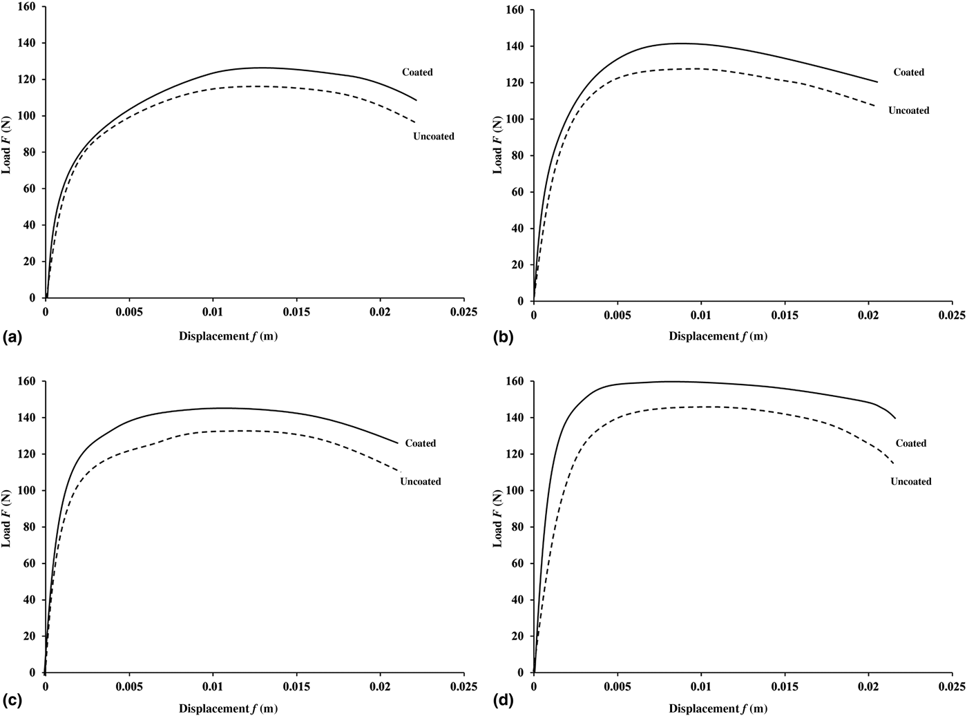
Figures 1(a)–1(d) indicate the load-displacement curves of the bare aluminum alloy at several strain rates (0.5, 2, 5, and 10 mm/min). It is clear that the increase of strain rate contributed to a rise in maximum load. In contrast, displacement appears to have remained relatively stable and was not considerably altered by changes in the strain rate. Maximum load increased with increasing strain rate as a result of the prevention of dislocation movement and of the decrease of the propagation velocity of the dislocations. Dislocations piled up at points of macro-shear band formation and at points of grain boundary decohesion.[Reference Jin, Fu, Zhang and Liu27]
Comparative load-displacement curves of uncoated and coated aluminum 6156-T61 alloy for (a) 0.5 mm/min, (b) 2 mm/min, (c) 5 mm/min, and (d) l0 mm/min strain rate.

Figures 1(a)–1(d) comparatively shows the load-displacement performance during three-point bending of the aluminum alloy with Ni coating at different strain rates (0.5, 2, 5, and 10 mm/min). The increase in strain rate contributed to a rise of maximum load, as displacement was not differentiated. This result can be attributed to augmented dislocation density, as well as to the prevention of movement of the dislocations and to the increase of the work hardening rate. At a constant strain rate, the coated samples displayed greater strength and rigidity than did the uncoated samples. This difference may be attributed to the high interfacial mechanical integrity of coating to substrate and to the impeded egress of dislocations at the interface.
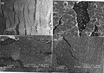
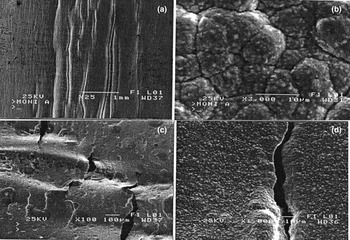
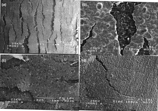
Figures 2(a)–2(d) and 3(a)–3(d), which refer to the tensile and compressive regions of bent nickel-coated aluminum alloys at different strain rates, clearly display a hemming effect, as well as delamination-spallation and falling back of the coating. The intergranular and transgranular crack branching were more intense in the tensile region than in the compressive region. In addition, the crack propagation from the nickel coating system into the substrate was hindered by crack splitting and crack stopping at the interface.
Surface morphology of the tensile region of nickel-coated aluminum 6156-T61 alloy for (a) and (b) 0.5 mm/min strain rate, (c) and (d) 2 mm/min strain rate.

Surface morphology of the compressive region of nickel-coated aluminum 6156-T61 alloy for (a) and (b) 0.5 mm/min strain rate, (c) and (d) 2 mm/min strain rate.

Comparison of the samples both with and without coating reveals that the holding load was greater in the case of the coated specimen at specific displacements. The difference in holding load suggests that a relatively thin coating (20 µm) can enhance the toughness of a specimen considerably. This 20 µm measurement refers to the nickel coating without including the 5 µm thickness of the zincate. In the case of the 20 µm coating, bending stiffness was measured at 17 × 10−17 Nm2. The maximum normal and shear stresses occurred at the coating–base material interface due to a notable difference in stiffness between the two. At this locus, there were defect points where crack initiation and failure of coating sources occurred. Stress relief of the coating was observed at the crack points, resulting in smaller and more closely located cracks. Along the direction of bending, the coating exhibited tensile shear deformation. Splitting separation of the coating occurred at the sharp edge crack sites.[Reference Jin, Fu, Zhang and Liu27–Reference Nemati, Majzoobi, Sulaiman, Baharudin and Azmah Hanim29]
Crack branching and deflection frequently appeared along the coating's crack path trajectory. As bending load increased, the cracking propagated linearly in each specimen's coating. Following this cracking, a high threshold load was required at the coating–bond coat interface for continued propagation of the crack into the bond coat. The threshold having been surpassed, cracks in the bond coat grew very quickly, and without any considerable additional loading.
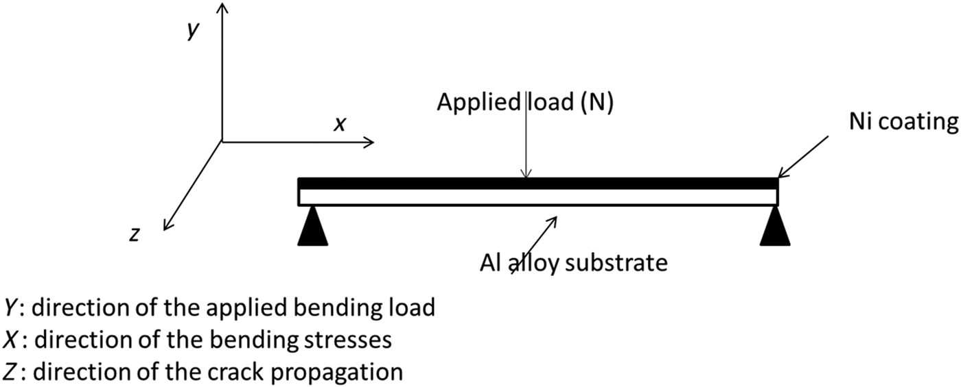
Figure 4 contains a sketch showing the direction of crack propagation. The fact that the specimens’ coatings showed multi-crack deformations constitutes a clear indication that the coating had no contribution to the substrate's plastic deformation. Generally, some areas showed complete elimination of the coating due to shear deformation where the coating and the substrate were in contact with one another. The coating fracture can be described as brittle. Furthermore, plastification was not noticed. Formation of discontinuous delaminated cracks was observed at the top coat–bond coat interface, with the result that spallation was observed in the top coat layer. Linear cracks initially appeared on the top coat layer surface at a right angle to the axis of loading. At the point where the surface crack tip was near the top coat–zincate (bond coat) interface, the crack was observed as veering off its original trajectory. These displaced cracks propagated along the interface. In addition, adhesion failure was also observed, which led to the substrate being separated from the coating.
Sketch of the bending load on the specimen and the direction of the applied stresses and the crack propagation.

Internal stresses developed due to tensile shearing, creating points of localized concentration of stress, particularly at defect points in the coating–substrate interface. Upon reaching critical stress levels at these defect points, total failure of the coating occurred and the coating itself peeled away from the substrate. The coating's internal stress was relieved around the crack sites. In cases where the energy necessary for crack propagation dissipated, the crack site would be limited to the substrate material and would terminate on the substrate's free surface.[Reference Ploypech, Boonyongmaneerat and Jearanaisilawong24–Reference Nemati, Majzoobi, Sulaiman, Baharudin and Azmah Hanim29]
Conclusions
• When comparing the load-displacement characteristics of the uncoated specimens to those of the coated specimens, the holding load proved greater in the case of the coated specimen at given displacements. Thus, a relatively thin (20 pm) coating does not appear sufficient to enhance the toughness of a specimen considerably.
• Increase in strain rate contributed to an increase of maximum load, due to the prevention of dislocation movement and the rise of dislocation density, in the case of both coated and uncoated samples.
• At a constant strain rate, the coated samples indicated greater strength and rigidity than did the uncoated samples due to their high interface fracture toughness (increased K ic). This can be attributed to the satisfactory interfacial integrity and the impeded egress of the dislocations.
• In the case of the uncoated alloy, surface roughening, strain localization (macro-shear bands), grain boundary decohesion and undulations were detected.
• The nickel-coated alloy displayed a total elimination of coating in the tensile region as a result of shear deformation at the coating–substrate interface. The coating exhibited brittle fracturing with no plastification. The formation of discontinuous delaminated cracks was observed where the top coat met the bond coat, resulting in the spallation of the top coat.
• Crack branching as well as crack deflection of the coating were observed along the crack path trajectory. Cracks propagated linearly in the coating of all specimens as bending load increased.
Acknowledgements
The authors would like to thank the members of the Physical Metallurgy Laboratory of National Technical University of Greece for their contribution to that research.