


I. INTRODUCTION
In the past decade, the Silicon–Germanium (SiGe) technology with transit frequencies exceeding 200 GHz [Reference Wanner, Lachner and Olbrich1] paved the way for mass market automotive radar applications which increased the driving safety in all vehicle classes. Therefore, a multitude of different sensor and antenna concepts were developed and commercialized. An overview of the current state-of-the-art concepts is given by Menzel and Moebius in [Reference Menzel and Moebius2]. Hereby, the customers demand an increased sensor performance at low sensor costs. In the past, the usage of radar sensors was limited to comfort systems, such as the adaptive cruise control (ACC) or the lane assist system. Future radar applications, such as the advanced emergency breaking system (AEBS), or applications like autonomic driving increase the demands for upcoming generations of radar sensors [Reference Hasch, Topak, Schnabel, Zwick, Weigel and Waldschmidt3]. Especially the angular separation at multiple target scenarios in one range cell is an important point for future radar concepts. An approach to deal with such challenges can be the usage of MIMO radar systems which were intensively discussed, e.g. by Fisher et al. [Reference Fishler4] in 2004. Nowadays, a multitude of different MIMO radar systems has been presented. Many of them are using planar phased array antennas, such as the MIMO concept from Feger et al. [Reference Feger5] in 2009. In this paper, a lens-based time-domain multiplex MIMO radar for automotive long-rang applications is presented. The sensor combines MIMO techniques and the advantages of a dielectric lens for optical spatial beamforming in the azimuth plane. First approaches and theoretical simulations and the signal model, which is shown in Section III, for such a system were presented in [Reference Lutz, Baur and Walter6]. A demonstrator system and measurements were presented in [Reference Lutz and Walter7]. In the elevation plane, the system is additionally feasible for DOA estimation, therefore a three-dimensional (3D) imaging of the surrounding can be obtained.
II. SYSTEM CONCEPT
The proposed system is realized as a multistatic four channel radar concept. Since the costs of the RF substrate forms a significant part of modern mm-wave radar systems the concept uses optical beamforming with a dielectric cylindrical lens to avoid large planar patch antenna arrays. Due to the short wavelength in the frequency band, lens antennas achieve a good performance combined with a small dimension and weight at high cost efficiency [Reference Binzer, Klar and Gross8]. Since the Fresnel numbers are low at 77 GHz, the lens-based beamforming is dominated by diffraction and in the far-field region a Fraunhofer diffraction pattern can be observed [Reference Hecht9].
The radar functionality is integrated in SiGe MMICs from Infineon Technologies [Reference Wagner10]. The frontend MMIC contains the TRX units, sensors for power and temperature monitoring and a digital control logic. Each channel is usable for receiving and transmitting with a programmable maximum output power of 0.dBm The mm-wave signal is generated externally in an additional VCO MMIC.
The block diagram shown in Fig. 1 gives an overview of the system. The transmitting waveform is generated by the VCO in combination with a fractional-n PLL. The PLL also contains an integrated waveform generator which is feasible to generate linear frequency chirps with a programmable modulation bandwidth and time. The feedback frequency for the PLL is generated by an integrated 1/32 frequency divider. The wave form generator allows fast FMCW chirp modulations [Reference Stove11] with modulation times down to 10 µs and a modulation bandwidth up to 3 GHz. All devices are controlled with a digital serial 3-wire bus. For the IF signal processing four parallel variable gain amplifiers are implemented. These amplifiers achieve an excellent performance with a programmable voltage amplification of −5 dB up to 45 dB and a low input noise. To avoid aliasing effects a programmable low pass filter is implemented. The usages of fast FMCW-modulated waveforms results in IF beat frequencies in the lower MHz range, hence the used AD converter uses a sampling frequency of 4 × 30 MHz.
Simplified block diagram of the proposed radar system.

Figure 2 shows a photograph of the radar system circuits. The RF board consists of a Rogers 3003 hybrid multilayer circuit board with six layers. Both 77 GHz MMICs are provided as state-of-the-art embedded wafer level ball grid array (eWLB) housed components [Reference Wagner10, Reference Brunnbauer, Meyer, Ofner, Mueller and Hagen12] and are mounted using an conventional soldering process – and no further complex mounting like gold wire bonding or flip chip is needed.
Photograph of radar system circuit boards. The antennas, MMICs, and the PLL system are located on the top board. IF signal amplifiers, power management, and digital control logic are located on the additional back side boards. Outline dimensions: 55 mm × 55 mm × 20 mm.
The complete system is feasable to run fast chirp modulations for range/velocity estimation based on a two-dimensional (2D) FFT algorithm [Reference Stove11]. Figure 3 shows the estimation result of a two target scenario. The scene was simulated using a physical radar target simulator and was measured with the MIMO radar sensor. Two targets were located at different ranges with the same velocity. Both targets are clearly identifiable without additonal matching.
Result of r/v estimation based on a 2D FFT transform. Two targets were simulated and measured at r = [44 m, 88 m] v = [−3.2 m/s, −3.2 m/s], t FMCW = 100 ms, and BW FMCW = 2 GHz.
A) Antenna array design
The antenna concept shown in Fig. 4 enables angular estimation in azimuth and elevation and was published in detail in [Reference Baur, Mayer, Binzer and Walter13]. The basic principle is the usage of phase information in one angular plane, and amplitude information in the other angular plane. Therefore an array of four series feed arrays is combined with a dielectric cylindrical lens. Figure 4 shows the top view of the antenna feed arrays. With the offset in y-direction combined the shaped dimension of the lens beam squints for the amplitude-based estimation are generated. In x-direction, the offset generates a phase difference which is used for a phase monopulse estimation.
Topography of the feed antenna array consisting of four series feed array patch antennas (Δx = 4 mm, Δx = 2 mm).
The antenna elements itself are traveling wave patch antenna arrays. For sidelobe reduction a taper function is applied to the width of the radiating elements.
B) Dielectric lens
To achieve narrow and well-formed beam patterns a dielectric cylindrical lens is used for optical beamforming in the azimuth direction. Due to the low Fresnel numbers for lens antennas at 77 GHz the beamforming system is dominated by diffraction and the focal area forms an Airy disc with the size of:
 $$x = 2.44 \cdot \lambda \cdot \displaystyle{{d_f } \over {d_a }}\comma \;$$
whereby λ is the wavelength, d f the focal length, and d a the aperture of the lens [Reference Volkais14].
Figure 5 shows a fullwave simulation of the near-field behavior of the lens used in the system at 77 GHz [Reference Baur, Mayer, Stockle, Lutz and Walter15]. The feed antenna elements are placed in the center of the focal region. The lens (aperture d a = 50 mm, focal length d f = 25 mm, and ε r = 3) consists of a homogeneous polyetherimid (PEI) plastic material and is fabricated using mechanical machining.
Near-field cross-section of the dielectric lens with plane wave illumination at 76.5 GHz. Red indicates the maximum of the electrical field in the Airy disc [15].
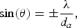
For the angular estimation of an incoming wave, an amplitude monopuls technique can be applied. Therefore at least two antenna beams, which are pointing in slightly different directions, are used. In the beam overlap area, an angular estimation can be obtained using amplitude comparison and correlation methods. The adjustment of the squinted beams can be easily obtained due to a displacement of the feeding elements from the focus of the lens [Reference Baur, Mayer, Stockle, Lutz and Walter15]. The second important parameter of interest is the beamwidth of the antenna system. Due to the diffraction the broadening of the beam is defined as:
 $$\sin \lpar \theta \rpar = \pm \displaystyle{\lambda \over {d_a }}\comma \;$$
where θ is the angle of the first intensity minimum, λ is the wavelength, and d a is the aperture size of the lens [Reference Hecht9, Reference Baur, Mayer, Stockle, Lutz and Walter15].
For the design of the beamforming system it is necessary to make a tradeoff between the beamwidth, which has a direct impact on the angular resolution and accuracy, the number of feeding elements and the needed angular coverage.
III. SIGNAL MODEL
As an simplified introduction, consider a two beam radar system. Figure 6(a) shows the beampattern of the assumed system, whereby the black and green pattern represent the first and the second beam, respectively.
Simplified two beam radar system with optical beamforming (a) with resulting two-way MISO beampatterns and (b) resulting MIMO two-way beam pattern.
In the conventional MISO configuration, both beams are used for ilumination and receiving. The resulting two-way diagram is shown in Fig. 6(a). In the MIMO configuration, single beams are used for illumnination and receiving. If the black beam is used as illuminating and receiving element, the black beampattern, shown in Fig. 6(b) is obtained as two-way response of the system – the behavior of the second blue beam is assignable. If different beams for transmitting and receiving are combined new additional two-way beampatterns are obtained. In this example, the combination of the black beam for transmitting and the green beam for receiving in Fig. 6(a), creates a new two-way beampattern in the middle of both original beam positions (red in Fig. 6(b)). In the practical application all beams are switched in time-domain multiplex. Therefore the power output of each TRX cell can be controlled electronically with a microcontroller where the maximum channel-to-channel isolation is approximately 30 dB.
In the following section, the specific signal model for the sensor is defined. Consider an antenna array with N = 4 antennas. Each antenna element can be used as transmitting and receiving element. Therefore, two identical steering vectors aTX(θ) for transmitting and bRX(θ) for receiving can be defined.
The signal vector at the receiving antennas x(t) is given by:
 $${\bi x}\lpar t\rpar = {\bi x}_s \lpar t\rpar + {\bi n}\lpar t\rpar \comma \;$$
where n(t) is Gaussian white noise and xs(t) is the target reflection signal which is given by:
 $${\bi x}_s \lpar t\rpar = \beta \left({{\bi a}_{TX}^T \lpar \theta \rpar \Phi ^H \lpar t\rpar } \right){\bi b}_{RX} \lpar \theta \rpar \comma \;$$
where β is the target reflection factor and Φ(t) = [Φ(t),⋯, ΦN(t)] is the waveform vector containing the different transmitting waveforms. If ⊗ is the Kronecker product, a virtual MIMO steering vector can be defined:
 $${\bi y}\lpar \theta \rpar = {\bi a}_{TX} \lpar \theta \rpar \otimes {\bi b}_{RX} \lpar \theta \rpar .$$
If dim(Φ) is equal to the number of transmitted waveforms and N is the number of receiving antennas of the maximum dimensions of the steering vector b, y is given by:
 $$dim\lpar y\rpar = dim\lpar {\bf \Phi }\rpar \cdot N$$
To obtain additional information, a beam squint between the transmitting and receiving antenna is required. Therefore, the majority of information is generated by the combination of neighboring beam positions and a reduced dimension MIMO channel matrix H can be applied which is given by:
 $${\bf H} = \left({\matrix{ {h_{1\comma 1} } & {h_{1\comma 2} } & 0 & 0 \cr {h_{2\comma 1} } & {h_{2\comma 2} } & {h_{2\comma 3} } & 0 \cr 0 & {h_{3\comma 2} } & {h_{3\comma 3} } & {h_{3\comma 4} } \cr 0 & 0 & {h_{4\comma 3} } & {h_{4\comma 4} } \cr } } \right)\comma \;$$
whereby h n,m represents the propagation path from the nth transmitter to the mth receiver. Due to the reduction of MIMO channels, the calculation time can be decreased, without reducing the angular estimation quality. Figure 7 shows the measured two-way antenna diagrams which are used as steering vectors. Figure 7(a) shows the conventional MISO configuration where all antennas are used for target illumination. Figure 7(b) shows the reduced MIMO configuration with the channel matrix defined in equation (7).
Plotted measured steering vectors of the MISO (a) and MIMO (b) configuration.
As illustrated in Fig. 1 in addition to the four physical beams, six additional MIMO beams are created and can be used for an improved DOA estimation.
IV. SYSTEM MEASUREMENTS
For performance measurements a sensor prototype was developed and several simulations and measurements have been undertaken. Figure 8 shows the sensor prototype mounted in an aluminum enclosure and covered with the dielectric lens.
Prototype setup of the presented radar system with the dielectric lens. Overall dimensions 75 mm × 75 mm × 60 mm
For the measurement of two-way diagrams and target scenarios, measurements in an anechoic chamber were done. The measurement setup is shown in Fig. 9. As targets corner reflectors with different RCS can be mounted on an angular positioning system.
Multitarget measurement setup in an anechoic chamber. The distance between the sensor and the corner reflector is 2 m and fulfills the far-field requirement. The sensor is mounted on a rotation stage for the measurement of the steering matrix.
The resulting two-way diagrams were shown in Fig. 7 in the previous section. The complete two-way antenna gain is about 40. The beam design achieves an azimuth angle coverage from −7.5° to +7.5°, with DOA estimation capability in the beam squint area from −5° to +5°. The two-way diagrams show a dynamic range of 20 dB. All following characterization techniques are based on the measured data.
V. SENSOR CHARACTERIZATION
In the following section, the sensor performance of the proposed radar system is investigated. Hereby the comparison between the conventional MISO configuration (all channels are used for the target illumination) and the MIMO configuration (every single channel is used for illumination in time-domain multiplex) will be the primary interest. The comparison is done using the main properties, for the angular estimation performance of a radar system: the ambiguities, the accuracy of the angular estimation, the angular resolution and the field of view of the radar sensor. To achieve an objective comparison between both configurations it is nesessary to adjust the observation time – so that the transmitted energies in both configurations become equal.
 $$T_{MIMO} \mathop = \limits^! T_{MISO} \mathop = \limits^! \sum\limits_{n = 1}^N T_n \comma \;$$
whereby T MIMO and T MISO is the MIMO and MISO observation time respectivly and T n it the observation time in the nth MIMO time-domain multiplex state. As a consequence from condition (8) the transmitted energies for the MIMO and MISO configuration are equal.
A) Field of view
The field of view shows the achievable detection area of the sensor in dependence of the range and the azimuth angle [Reference Binzer, Klar and Gross8]. For the field of calculation and a comparison between the MISO system and the MIMO system some boundary conditions have to be defined: for detection signals in two beams over the receiver input sensitivity of −120 dBm are required. The target RCS is assumed with 10 m2. The calculated field of view exhibits advantages of the MIMO configuration (b) compared to the MISO (a) configuration, in the range and azimuth coverage.
The visualized field of view in Fig. 10 shows two major effects of the usage of the MIMO configuration. At first, the usable azimuth angle area can be increased due to the availability of additional beams in the edge regions. Secondly since addtional beams are located between the beam positions of the MISO configuration blind spots in the long-range region are erased effectively.
Calculated field of view of the radar sensor in MISO and MIMO configuration based on measured antenna diagrams.
B) Array ambiguities
To achieve a reliable estimation of the target azimuth angle, the ambiguity of the estimation is an important point of interest for the characterization. For the array ambiguity investigation of the autocorrelation function of the two-way antenna diagrams is observed and given by Sullivan [Reference Sullivan16]:
 $${\bi akf}\lpar \theta \rpar = \displaystyle{{\left\langle {{\bi y}\lpar \theta \rpar \comma \; {\bi y}\left({\theta _0 } \right)} \right\rangle } \over {\left\vert {{\bi y}\lpar \theta \rpar } \right\vert \left\vert {{\bi y}\left({\theta _0 } \right)} \right\vert }}\comma \;$$
where akf(θ) is the auto-correlation function for θ shown in Fig. 11 and y(θ) is the used steering vector. The width of the red maximum correlation is a characteristic value for the accuracy of the angular estimation which will be discussed in the next section.
Measured array ambiguity function of the MISO (a) and MIMO (b) configuration. Red color indicates the highest value of the auto-correlation result, blue the lowest one.
The plotted ambiguity function shows that the angular estimation is unambiguous for the angular range of ±5° in the MISO case. Outside the ±5° area the ambiguities increase rapidly due to the absence of further beams. In the MIMO case the unambiguousness is increased up to ±7° due to the availability of additional beams. Furthermore, some ambiguities outside these areas are supressed. In Fig. 11(a) an ambigutiy at −10° and 2° is observed. This can lead to a wrong angular estimation in scenarios with short-range high RCS targets meaning that the strong target at −10° could apear at 2°. This ambiguity is effectively supressed due to the MIMO configuration shown in Fig. 11(b). As a consequence of the availability of additional beams, it is at least plausible, that the appearance of a target at −10° in the different beams should differ from the appearance of a target 2°. Therefore, the ambiguity decreases with respect to the angular estimation, which is reflected in the array ambiguity of Fig. 11. The influence of the usage of the MIMO configuration depends strongly on the chosen antenna array geometry. Especially when non-uniform feeding arrays are used, the influence on the ambiguity supression is stronger compared to the presented array geometry.
C) Cramer–Rao lower bound
For the angular accuracy estimation of the system, the Cramer–Rao lower bound (CRLB) is investigated. The CRLB is defined as the inverse Fisher information matrix and is the theoretical lower bound of any unbiased estimator and therefore of the angular accuracy of the radar concept [Reference Kalkan and Baykal17, Reference Li and Stoica18]. For the given boundary conditions the CRLB is calculated by:
 $${\rm CRLB}\lpar \theta \rpar = \displaystyle{1 \over {2 \cdot n \cdot {\rm SNR}}} \cdot \displaystyle{1 \over {\left\vert {{\bi y^{\prime}}{\bf \lpar }{\bi \theta }{\bf \rpar }} \right\vert ^2 - \left\vert {\left\langle {{\bi y}\lpar \theta \rpar \comma \; {\bi y^{\prime}}\lpar \theta \rpar } \right\rangle } \right\vert ^2 }}\comma \;$$
where n is the number of active beams, SNR is the averaged signal-to-noise ratio over all beams, θ is the azimuth angle, y(θ) the normalized complex steering vector and y′(θ) the angular derivate. Since the antenna arrays do not consist of isotropic radiators the derivate of y cannot be obtained analytically. So a numerical calculation of the derivate of the measured steering vectors is necessary.
The result of the Cramer–Rao bound in Fig. 12 shows a significant dependency on the azimuth angle. In the center region around 0°, the CRLB indicates a high angular accuracy, which can be significantly increased by applying MIMO techniques. This is due to the fact that additional beams reduce the CRLB (factor n). Furthermore, because of the narrowing of the beams in the MIMO configuration the angular gradients become steeper and lower the CRLB additionaly. Furthermore, the useable detection range of the MIMO configuration is broadened by about 3° in the azimuth dimension due to the availability of additional beams in the edge regions of the antenna pattern. From Fig. 6 it is obvious that the additional MIMO beam is shifted with respect to the MISO beam thus an additional beam localized between the two MISO beams is created. This results in an extended angular range where at least two beams with sufficient SNR for angular estimation are available.
Cramer–Rao lower bound of the radar concept for a SNR = 30 dB. MISO and MIMO configurations are marked red and blue, respectively. Calculation of the CRLB base on measured steering vectors.
D) Angular resolution
For the final sensor characterization the angular resolution is investigated. In complex urban radar scenarios or situations with multipath propagation more than one target in a range cell can occur. These scenarios are a demanding task for the angular target separation capability of the radar sensor. For conventional estimators, like classical beamforming the angular separation is limited by two requirements: at first, the availability of sufficient beam information (three for two targets) and secondly the beam width.
Since the angular separation with a conventional estimator is limited through the beam width a simplified least-square estimation for the investigation of the target separation performance is done:
 $$min \lcub {\bi r} \lpar {\theta_1\comma \; \theta _2 \comma \; }\rpar \rcub = \Vert {\bi x} - \lpar {\bi y} \lpar {\theta _1}\rpar + {\bi y}\lpar {\theta _2}\rpar \rpar \Vert\comma \;$$
where r is the residual which is minimized. x is the vector of the received antenna voltages, y(θ 1) the corresponding steering vector of the first target, and y(θ 2) of the second target.
The result given in Fig. 13 shows the residuals for a measured two target scenario (same radar cross-section). The results exhibits two minima for the residuals at [0, −2] and [−2, 0], respectively. Furthermore, it shows clearly that the target position is not resolved in the MISO configuration (a). In the MIMO result (b), the targets are identified clearly without any ambiguity at −2° and 0°.
Plotted residuals of the maximum least-square estimator. Two measured targets at θ = [0, −2] Minimum residuals are marked red. (a) MISO configuration (not separable) and (b) MIMO configuration (separable).
VI. CONCLUSION
In this paper, a new highly integrated SiGe MIMO radar sensor for the 76 GHz–81 GHz frequency band was presented. A sensor prototype was built and characterized. Due to the usage of switchable TDM MIMO configurations in combination with a dielectric lens the sensor performance can be significantly improved. The accuracy is increased, and ambiguities are reduced. The usable angular range for estimations is also enlarged due to new additional beam information in the boundary regions of the antenna diagram. For angular estimation and separation the angular target separation with conventional estimation algorithms like beamforming is limited by the beam width as well as in the MISO and in the MIMO case. For super resolution algorithms – like the maximum-likelihood estimator – this limitation can be overcome and leads in the MIMO case to a significant improvement of the angular resolution. In the majority of common radar scenarios on the road, the conventional MISO radar performance is sufficient. To reduce the calculation effort for radar signal processing in standard scenarios, and increase the sensor performance in complex surroundings a scenario adaptive MIMO technique can be introduced to resolve ambiguities or improve the angular resolution in complex scenarios A critical point in the system architecture is the time invariance of the observed target scenario. To avoid additional movement compensation techniques like those in [Reference Schmidt, Feger, Pfeffer and Stelzer19] the modulation time of the FMCW signal should be kept short, so that a complete MIMO observation takes less than some ms. The fast chirp modulations offer additional effective methods for range/velocity estimation and matching using the classical 2D FFT approach or new and advanced signal processing algorithms like compressed sensing. The combination of the switched MIMO method and these algorithms requires a sufficient correction of the system phase terms which are not discussed in this contribution. Efficient methods for this correction are discussed, e.g. in [Reference Schmidt, Feger, Pfeffer and Stelzer19] or [Reference Guetlein, Kirschner and Detlefsen20]. However, the measurement results of the system indicate a very good performance in all relevant cases. In future, the investigation of larger multichannel systems and the adaption of eigenvalue-based DOA estimation methods to lens-based MIMO radar will be part of the research. Furthermore, compressed sensing methods such as the l 1-magic algorithm [Reference Candes, Romberg and Tao21] are currently implemented to reduce the amount of sampled data as well as the sampling freqeuncy of the AD converter.
ACKNOWLEDGEMENTS
This work was funded by the German Federal Ministry of Education and Research (BMBF) within the project RADAMES in cooperation with the Robert Bosch GmbH. SiGe-MMICs, dielectric lenses and helpful discussions were provided by the Robert Bosch GmbH, Stuttgart and Infineon Technologies, Munich, Germany.
Steffen Lutz was born in Ulm, Germany in 1986. He received his Master degree in Systems Engineering from the University of Applied Sciences Ulm, Germany in 2011. Since then he is with the Laboratory at Microtechnology of the University of Applied Sciences Ulm and is working toward his Ph.D. in cooperation with the University of Erlangen-Nuremberg on the field of mm-wave MIMO radar. His research interests include RF and radar system design, sensor signal array processing as well as antenna design.
Thomas Walter received his diploma degree (1990) and Ph.D. (1995) degree in Electrical Engineering from Stuttgart University, Germany. He then joined the corporate research of Bosch/Stuttgart working on Microsystem Technology and optical communication systems. In the business unit driver assistance systems of Bosch, he was responsible for the introduction of SiGe MMICs into automotive radar sensors. Since 2005 he has been a professor for Microelectronics and Microsystem Technology at the University of Applied Sciences Ulm, Germany. In 2012, he received the “Wissenschaftspreis der Stadt Ulm” (Scientific Award of the City of Ulm). His main research interests include future concepts for automotive radar as well as long-term stability of semiconductur devices.
Robert Weigel was born in Ebermannstadt, Germany, in 1956. He received the Dr.-Ing. and the Dr.-Ing.habil. degrees, both in Electrical Engineering and Computer Science, from the Munich University of Technology in Germany, in 1989 and 1992, respectively. From 1982 to 1988, he was a Research Engineer, from 1988 to 1994 a Senior Research Engineer, and from 1994 to 1996 Professor for RF Circuits and Systems at the Munich University of Technology. In winter 1994/95, he was a Guest Professor for SAW Technology at Vienna University of Technology in Austria. From 1996 to 2002, he has been the Director of the Institute for Communications and Information Engineering at the University of Linz, Austria. In August 1999, he co-founded DICE – Danube Integrated Circuit Engineering, Linz, an Infineon Technologies Design Center (DICE) and an Intel company (DMCE) which are devoted to the design of, respectively, industrial electronics and mobile radio electronics. In 2000, he has been appointed Professor for RF Engineering at the Tongji University in Shanghai, China. Also in 2000, he co-founded the company Linz Center of Competence in Mechatronics. Since 2002 he is head of the Institute for Electronics Engineering at the University of Erlangen-Nuremberg, Germany. In 2009 and 2012, respectively, he co-founded the eesy-id in Erlangen and eesy-ic in Nuremberg, both dealing with electronics engineering.
He has been engaged in research and development on microwave theory and techniques, integrated optics, high-temperature superconductivity, SAW technology, digital and microwave communication systems, and automotive EMC. In these fields, he has published more than 700 papers and given about 300 international presentations. His review work includes European and Asian research projects and international journals. In 2002, he received the German ITG Award, and in 2007 the IEEE Microwave Applications Award.
Dr. Weigel is a Fellow of IEEE, a member of the The Electromagnetics Academy, and a member of the German VDE and the Austrian ÖVE. He serves on several editorial boards such as the Proceedings of the IEEE and advisory boards of companies and research institutes. He is the elected speaker of the Electrical Engineering faculty of the German Research Foundation (DFG) and an elected member of the German National Academy of Science and Engineering (acatech). Within IEEE MTT-S, he has been Founder and Chair of the Austrian COM/MTT Joint Chapter, region 8 Coordinator and, during 2001 to 2003 Distinguished Microwave Lecturer. He is the 2014 MTT-S President and the chair of MTT-2 Microwave Acoustics. Dr. Weigel was the General Chairman of the 2013 European Microwave Week in Nuremberg, Germany.



