

1 Introduction
E-Manufacturing covers a single, complete set of operational capabilities including rapid plant design and deployment, real-time ERP connectivity, comprehensive asset management of people, products and processes, along with a seamless coupling to the entire supply chain via the Web. E-Manufacturing integrates customers, e-commerce systems and suppliers in the manufacturing process to provide an Internet-based strategic framework for the factory (Lee, Reference Lee2003).
E-Manufacturing assumes a very relevant role regarding the possibility of supporting networks of small–medium enterprises (SMEs) in filling their technological gap with respect to wider organizations. Networked SMEs are very important sources of creativity as well as important factors of growth for many countries. This is particularly true in the contemporary globalization context, where manufacturing processes are often distributed over wide geographical areas in order to reduce production costs and timing.
In this scenario, the usual activities to design and manufacture innovative products for SME networks is more complicated, due to difficulties in communication and coordination with people at distant sites. Obviously, such difficulties depend on many factors: it is highly probable that large organizations and enterprises can exploit effective and efficient technologies to reduce their impact on the decision-making processes, but typically this is not true for SMEs.
For these reasons a new and challenging scenario for Knowledge Management (KM) can be investigated: the development of conceptual and computational frameworks to help networked SMEs in the very difficult task of building shared knowledge models. Such frameworks should enhance the SMEs’ knowledge and add value to the organizations involved.
However, supporting SMEs with software products covering all the E-Manufacturing issues can be difficult because of the SMEs’ limited equipment, funds and technical capabilities (Mason et al., Reference Mason, Castleman and Parker2004; Jin et al., Reference Jin, Wen and Oraifige2007). According to Burgelman et al. (Reference Burgelman, Christensen and Wheelwright1996), it is strategic for SMEs to focus on innovation, that means focusing on skills, expertise and knowledge for maintaining competitiveness on the global market. As was pointed out by Kim Chung and Tibben (Reference Kim Chung and Tibben2006), the innovative capacity of SMEs per se is limited.
The adoption of E-Manufacturing principles is necessary for SMEs joining a network to overcome their natural difficulties in equipping themselves with a good technological platform through the sharing of tools, applications and methodologies with other subjects. KM can be profitably exploited in this context to build knowledge models and to propose approaches for the development of decision support systems, which help members of the network to improve their innovation level. This is particularly true when dealing with clusters of SMEs involved in the design and manufacturing of mechanical products, which are traditionally the most difficult to support with computer applications.
In this paper, we present an approach based on semantic Web technologies for the design and development of KM systems for SME-based E-Manufacturing. In particular, our approach is based on ontologies and on the exploitation of NavEditOW (Bonomi et al., Reference Bonomi, Mosca, Palmonari and Vizzari2007), a tool supporting the rapid design and development of semantic Web applications. This tool provides developers with a number of ready-to-use functionalities for semantic navigation, ontology editing and query, which can be still extended and configured depending on the application.
The tool, already tested and exploited in different domains such as Archaeology (Bonomi et al., Reference Bonomi, Mantegari and Vizzari2006) and e-Government (Palmonari et al., Reference Palmonari, Viscusi and Batini2008), allows developers to focus on the knowledge model of the application, that must be provided as a Web Ontology Language—Description Logics (OWL-DL) ontology.
However the design of an ontology from scratch can be a hard and time-consuming task. For this reason one of the main aims of this paper is also to present an upper-level axiomatic functional ontology, represented in OWL-DL (Knublauch et al., Reference Knublauch, Musen and Rector2004), which can be given as input to NavEditOW and can be therefore instantiated for different application domains.
There are two main reasons for the choice of ontologies as models: on the one hand, ontologies provide a powerful modeling framework (Sugumaran & Storey, Reference Sugumaran and Storey2002); on the other hand, conceptual ontological models can be exploited to enable knowledge sharing over the Web, if they are represented with well-known semantic Web languages such as OWL-DL.
In order to show the effectiveness of the approach, we present an example of application built for supporting a network of SMEs involved in the design and manufacturing of a supermotard bike, namely Terra Modena 198. This product is the result of a complex decision-making process characterized by a very low impact of technologies on the product lifecycle, with consequent problems in managing communication among the actors (e.g. suppliers of raw materials or semi-manufactured parts, customers and so on) as well as the different steps of the manufacturing process.
The paper is organized as follows: Section 2 introduces the main problem this paper focuses on presenting as a case study the SMEs’ cluster producing the Terra Modena 198 bike. Related work is discussed in Section 3, where two main research topics are addressed, namely KM for SMEs support and functional design ontology. The main functionalities of the semantic Web application framework NavEditOw are presented in Section 4, while the top-level functional design ontology is described in Section 5. Section 6 discusses the case study, the domain ontology and some of the features provided by the resulting application. Finally, Section 7 ends the paper with some concluding remarks.
2 Problem context and motivation
The usual activities to design and manufacture innovative products are more complicated when networks of SMEs are concerned, due to difficulties in communication and coordination with people at distant sites.
On the other hand, it is evident how the establishment of strategic alliances has become necessary for modern organizations to improve their chances for survival in the globalized market (Gulati & Singh, Reference Gulati and Singh1998): SMEs internal organization are often inadequate and alliances with other firms help to overcome this shortcoming (Marino et al., Reference Marino, Strandholm, Steensma and Weaver2002). The collaboration among SMEs operating in different contexts allows for the mutual enhancement of skills and resources and the creation of communities of practice (Wenger, Reference Wenger1998), diffusing heterogeneous knowledge. This knowledge should be properly captured in order to support SMEs in their decision-making processes about common interests, products, services and so on.
Networks of SMEs should be analyzed before developing systems to support them properly. In this sense, a very important reference is the work by Arni Sverrisson (Reference Sverrisson2000), who proposed a classification of SME clusters according to three indexes, (1) the main observable indicator of each type, (2) the main observed benefits coming from collaboration and (3) the type of technological dynamic interaction among firms: location, characterized by (1) proximity of firms, (2) information exchange, (3) imitation; local market, characterized by (1) many similar activities, (2) easy access/competition, (3) product development; local network, characterized by (1) division of labor, (2) specialization, (3) complementarities; innovative, characterized by (1) local novelties, (2) adapting, (3) reverse engineering; industrial district, characterized by (1) formalized cooperation, (2) collective competition, (3) collective invention.
This classification is a very interesting starting point to understand what kind of networked SMEs is the subject of KM intervention. By combining indexes and typologies it is possible to derive new and hybrid forms of collaboration among SMEs. Moreover, the classification can help in the choice of KM methods, and tools can be adopted to develop ad-hoc solution for a given cluster of SMEs.
In particular, in our opinion, the most promising SME cluster type to support with a KM project is the local network. Since they are characterized by the division of labor and specialization, a KM project could be very useful to support the sharing of knowledge that could be otherwise absent. In fact, each member of the network could focus only on the execution of its own tasks without a clear idea of the global state of the process. The risk of this situation is that mistakes in the product and design manufacturing process can only be detected at the end of the decisional process, without the possibility of correcting them before, with the consequent loss of time and money.
In this paper, we want to propose a case study of local networks involved in the design and manufacturing of a mechanical product, namely a supermotard bike, where the high level of specialization and division of labor established among the partners and the absence of an adequate technological platform to support communication and information exchange often lead to making errors in the manufacturing process. The bike name is Terra Modena 198 and the network that produces it is the subject of the next sections.
2.1 The Terra Modena network
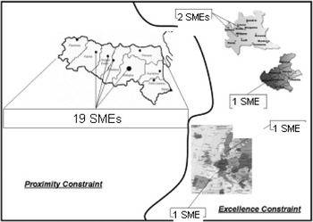
The network of SMEs (see Figure 1) considered as a case study in this paper is devoted to the design and manufacture of a supermotard bike. This product is a kind of hybrid object, since it has the characteristics coming from both the enduro and highway sectors. For example, the driving position on a supermotard bike is typical of enduro, as well as some parts of it (e.g. suspensions), while performances (e.g. speed) are very similar to a highway vehicle. For this reason, the project and manufacturing of a supermotard motorbike requires very deep knowledge in both fields and the ability to manage heterogenous aspects in engineering design.
The partners involved in Terra Modena 198 design and manufacturing

Terra Modena 198 is produced by an Italian SME called I-TEA. I-TEA is located in one of the most important Italian regions from the automotive sector point of view, that is, Emilia Romagna. There it is relatively easy to find experts in this field. I-TEA is the place where the different parts of the bike are finally assembled, but each of these components is produced by external partners. The partners of I-TEA are chosen according to a couple of constraints: proximity constraint, that means to find a partner for the realization of a bike part near to I-TEA, in order to save production costs and times; excellence constraint, that means to choose the best partner in Italy or outside Italy in case of proximity constraint unsatisfaction, in order to be sure that the manufactured parts will be perfect. Inside the network, I-Tea acts as a sort of communication center, managing the interaction among partners and evaluating results of different design activities.
2.2 The Terra Modena 198 life cycle
It is important to highlight that the decision-making process concerns all the functional parts of the bike except engine and transmission. In particular, from the point of view of partners’ interactions, the life cycle of Terra Modena 198 can be summarized as follows: Design, I-TEA decides the bike aspect and talks about it with a partner who is responsible for the definition of the three-dimensional (3D) models of all the components. This step ends when I-TEA accepts the 3D layout; Engineering: the layout is transformed into the motorbike matematica that is a complete, virtual and quantitative model of the final product. This step is accomplished by the I-TEA Engineering Department; Modeling and Manufacturing: starting from the Matematica, a consortium of three partners collaborates to build the bike components. First of all, a prototype of all the components considered in the first two steps is defined. The prototype is typically made in wood or polystyrene. Then, the prototype is transformed into carbonium and steel components of the final product. At the same time, the electronic system is also produced, thanks to the collaboration among three SMEs specialized in the manufacturing of electronic circuits and cables; Assembling: finally, all the bike parts are assembled by I-TEA mechanics. The detection of errors is made at this step, with the consequent, possible revision of one or more of the previous phases. At the end of the assembling phase, the bike is ready to be tested.
The most important step of the lifecycle is the modeling and manufacturing one: this is because during this phase I-TEA does not have full control on the decision-making process, and the interaction among partners involved in the design and manufacturing of carbonium, steel and electronic parts of the bike could produce something which is significantly different from the initial requirements or which is difficult for the mechanics to assemble.
Another problem arising from the complexity of the relationships among network partners is the management of atomic and semi-manufactured parts of the bike: it is possible that during the assembling phase some components of the final product cannot be completed due to the absence of some of them.
A knowledge acquisition campaign has allowed us to verify the reasons for these problems. We understood that the most important cause of difficulties in correctly accomplishing all the phases of the lifecycle is that each partner does not have a clear and complete view of the bike: in other words, each member of the network executes his/her own task without thinking about possible unpredictable critical situations that could emerge from his/her mistakes or misunderstandings.
Thus, the main problem to solve in the case of Terra Modena was the creation of a tool to promote knowledge sharing among the network enterprises. For this, our solution has exploited the semantic Web paradigm that can give a shared definition of the supermotard bike, as well as a clear identification of each SME role within the decision-making process through the use of functional ontologies. The next sections are devoted to describing the conceptual framework we have developed, as well as the computational tool adopted for the navigation, editing and querying ontologies over the web, in order to deal with the geographic distribution of network partners.
3 Related works
In this section we discuss some related work carried out in two key areas addressed by this paper: KM supporting SMEs and functional design ontology.
3.1 Knowledge management for small–medium enterprises
There has been a great deal of research in the KM context, both from the theoretical and the practical standpoint to support SMEs in their day-to-day activities and to join SME networks. From the theoretical point of view, many conceptual framework have been developed, starting from the well-known work by Nonaka and Takeuchi (Reference Nonaka and Takeuchi1995) who distinguish between tacit and explicit knowledge and adopt the knowledge creation spiral to represent them. This model describes a dynamic environment where tacit and explicit knowledge are continuously exchanged and transformed through socialization, combination, externalization and internalization.
Another important contribution comes from Handzic (Reference Handzic2006), who highlights the relevance of KM for SMEs, given that typically they have no more than 50 employers. Handzic argues that although the small size of an enterprise is a benefit from the agility perspective, on the other hand it is a drawback when looking at the consequent vulnerability in terms of loss of key personnel.
This is probably the key aspect in dealing with the development of KM systems for supporting SMEs: a KM application must take into account the creation of a knowledge model helping the SME to survive in case of the absence of one or more experts. This is particularly true in the case of networked SMEs, where experts are geographically distributed: the loss of communication between two members of the cluster should not generate loss of time (and consequently money) in the whole decision-making process.
The main aim of a KM project in the networked SMEs should then be the representation of knowledge in order to create shared models that can help each SME to keep the current state of the project under control, without delays in receiving inputs and producing outputs.
From the practical standpoint, many researchers have focused on the development of decision support systems to allow SMEs to increase their technological level in many different fields. For example, the Symphony project (Bandini et al., Reference Bandini, Mereghetti, Merino and Sartori2007) was funded by European Community to develop a KM system to support experts of human resources of SMEs in the employer selection process. In this experience, candidate profiles were compared according to a case-based reasoning approach (Aamodt & Plaza, Reference Aamodt and Plaza1994).
It is still very difficult to build effective KM systems for networked SMEs, due to logistic problems in acquiring, representing and implementing knowledge owned by experts who are not physically in the same place: typically, these systems are characterized by the fusion of different kinds of computer-based applications into a unique computational framework.
A significant experience in this sense comes from the KNOW-CONSTRUCT project (Soares et al., Reference Soares, Simoes, Silva and Madureira2006), which aims at providing SMEs in the construction sector with a sophisticated information management platform and community building tools for knowledge sharing. The KNOW-CONSTRUCT system exploits ontologies for building reusable pieces of knowledge about the construction domain; the domain knowledge is then structured and classified according to its use into specific meta models, suitable for building knowledge repositories for construction industries, called CIK (construction industry knowledge).
This model contains information and knowledge about products, processes, problems, best practices, legislative issues and so on. It is used by the KM system for exporting two kinds of functionalities: customer needs management (CNM) and knowledge community support (KCS).
The second functionality is more interesting from the KM perspective, since it concerns the development of technologies, methods and tools to support knowledge sharing and maintenance over a web-based architecture. For this, semantic Web technologies are fundamental in order to provide systems with the capability to retrieve complex and heterogeneous information, generated both internally and externally for the knowledge community.
In the following, we will present an approach similar to the one adopted by KNOW-CONSTRUCT developers, where functional ontologies are used to build a meta model of a complex mechanical product that is the result of a collaboration among a collection of SMEs. Through the use of upper-level functional ontologies and the semantic web approach, it has been possible to help the network overcome problems in communication due to the lack of an opportune technological infrastructure. Consequently, the development of a shared model of knowledge involved in the decision-making process has been possible. This has given a clear definition of roles and the implementation of ERP functionalities that are very useful to solve organizational problems.
3.2 Functional design ontologies
Traditionally, researches on ontology in Computer Science regard the development of conceptual and computational frameworks to manage the negotiation and sharing of meanings among different agents or communities (Bouquet et al., Reference Bouquet, Don and Serafini2002). In these frameworks the problem that ontologies must solve concerns the definition of a common terminology with which agents and communities can efficiently exchange and search useful information and structured data.
The development of semantic applications based on ontologies can take advantage of many results and tools. In particular, the languages of the OWL family offer the possibility to share ontological knowledge over the Web through XML-based mark-up languages; these languages are provided with formal semantics based on Description Logics, and it is possible to reason on the represented knowledge by exploiting off-the-shelf reasoners and inference engines (e.g. Tsarkov and Horrocks, Reference Tsarkov and Horrocks2006). Querying languages such as SPARQLFootnote 1 have been defined and are provided by most of all the most-used ontology repositories: among them, NavEditOW is a tool supporting the rapid design and development of semantic Web applications based on OWL-DL ontologies; for a complete overview of the application we refer to (Bonomi et al., Reference Bonomi, Mosca, Palmonari and Vizzari2007), where the relationship between this application framework and relevant related work is also discussed. The main functionalities with respect to ontology navigation, editing and query that the NavEditOW offers to designers of semantic Web application are summarized in Section 4.
From the perspective sketched above, ontologies can be exploited to exchange knowledge, and in particular, by using the Web as a communication medium. The above-mentioned KNOW-CONSTRUCT project (Soares et al., Reference Soares, Simoes, Silva and Madureira2006) exploits ontologies from this perspective. However, the ontology-driven applications that form the basis, particularly when their design is supported by state-of-the-art tools like NavEditOW, require the definition of OWL-based ontologies. The definition of ontologies is time-consuming and requires expertise in knowledge representation, in particular when expressive axioms are exploited to support automated reasoning. Regarding the domain addressed in this paper, that is, the design of complex mechanical objects, different ontological approaches have been proposed for the development of computational models supporting engineering design activities. At a high level of abstraction, Engineering Design consists in taking actions on the structure of an object (on its parts), according to requirements and high-level specifications. A number of references in literature (Umeda et al., Reference Umeda, Ishii, Yoshioka, Shimomura and Tomiyama1996; Bracewell & Wallace, Reference Bracewell and Wallace2001; Chiang et al., Reference Chiang, Pennathur and Mital2001; Deng, Reference Deng2002; Kitamura et al., Reference Kitamura, Sano, Namba and Mizoguchi2002) indicate that the competence of engineering designers is related to their ability to consider functional constraints over the parts of the objects they are designing. The traditional engineering design research community has widely accepted this conceptual design methodology (Gero & Maher, Reference Gero and Maher1997): first, a designer determines the entire function of a design object by analyzing the specifications of the product to be built. He/she then recursively divides the function into subfunctions, a process that produces a functional organization. In correspondence to each subfunction, the designer uses a catalogue to look up the most appropriate elements (a component or a set of components) that are able to perform the functional requirement. Finally, the designer composes a design solution from those selected elements.
Here, function plays a crucial role because the results of the design depend entirely on the decomposition of the function and on the designer’s capability to build the appropriate object that realizes that function (Chandrasekaran, Reference Chandrasekaran1990). As a result, a designer obtains a micro-macro hierarchy of functions that are projected on the aggregate of parts which the composite objects is constituted of. Thus, when designers speak about the ‘function’ held by an object or by one of its components, they can speak about it because they have sufficient knowledge for associating functions to a suitable object structure. In other words, ontological knowledge on functions is put into action by designers for describing design entities in terms of part-whole relations induced by the functional decomposition (Gero & Maher, Reference Gero and Maher1997).
Functional ontologies in Ontological Engineering have been properly developed in order to design knowledge bases representing the conceptual association between the expected effects of the devices and the ways of achieving these effects (Chandrasekaran et al., Reference Chandrasekaran, Josephson and Benjamins1999; Chandrasekaran & Josephson, Reference Chandrasekaran and Josephson2000). A functional representation is mainly aimed at giving an integrated description of what the design object has to achieve (i.e. its functions and behaviors) from how it can achieve its goals (i.e. its structure) (Gero, Reference Gero1990; Stahovich et al., Reference Stahovich, Davis and Shrobe1993; Umeda & Tomiyama, Reference Umeda and Tomiyama1997).
As discussed in Colombo et al. (Reference Colombo, Mosca and Sartori2007), these knowledge models have been traditionally inspired by the Function–Behavior–Structure (FBS) model (Gero & Kannengiesser, Reference Gero and Kannengiesser2003), a well-known conceptual schema representing the typical life cycle of a decision-making process in designFootnote 2.
Once the general map between the expected effects of the devices and the ways of achieving them has been realized (case studies and applications can be found in Kitamura et al. (Reference Kitamura, Sano, Namba and Mizoguchi2002)) these knowledge models can be exploited either as knowledge-bases to the support of computer aided design systems (Chandrasekaran & Josephson, Reference Chandrasekaran and Josephson2000; Gero & Kannengiesser, Reference Gero and Kannengiesser2003) or as metadata for functional annotations supporting document management services (Kitamura et al., Reference Kitamura, Washio, Ookubo, Koji, Sasajima, Tafakuji and Mizoguchi2006).
Especially in Ontological Engineering (Kitamura et al., Reference Kitamura, Sano, Namba and Mizoguchi2002) functional descriptions are typically aimed at giving a conceptual map over general engineering domains (mechanical, electronic, etc.). The assumptions that drive the functional models arrangement are normally rooted into physics (Umeda et al., Reference Umeda, Ishii, Yoshioka, Shimomura and Tomiyama1996). In other words, artifacts are conceived as material substances for quantitative physical forces (so-called device ontologies) and functions are seen as labels for collecting different objects under a same behavior.
The above-discussed models agree at a certain extent on the adoption of the FBS model in the field of Engineering Design. E-Manufacturing of mechanical products involving networked SMEs is basically concerned with objects of the same nature of the objects the Engineering Design deals with. Therefore we argue that the above-discussed approaches can be elaborated in order to develop a reusable upper-level functional design ontology (UFDO) that could be helpful in order to support semantic-intensive E-Manufacturing applications. We argue that such ontological descriptions of mechanical products can be profitably spent in order to face a well-known engineering activity bottleneck that the design process suffers from, especially in the case of networked enterprises.
To the best of our knowledge an OWL-DL formalization of such an ontology is not provided in the literature. A work embracing this Engineering Design perspective for semantic document management providing metadata for functional annotations is the above-mentioned (Kitamura et al., Reference Kitamura, Washio, Ookubo, Koji, Sasajima, Tafakuji and Mizoguchi2006). However, this ontology is aimed at providing generic classes of various types of functions, and it does not formalize the overall relationships between the structural and functional representation of objects.
The UFDO proposed here basically agrees on the main principles of the FBS-based models; in particular, the idea of providing a joint representation of the functional and the structural aspects of objects, the idea of representing these aspects through functional decompositions and structural mereologies and the idea of establishing connections between the two perspectives are at the basis of our UFDO.
The UFDO proposed then extends these ideas introducing a new classification of functions and design objects orthogonal to the classification related to functional decomposition. Moreover, the different design actors and the businesses involved in the manufacturing process are also explicitly represented in the ontology.
Instead, we do not treat behaviors and functions separately; in fact, taking behaviors into account and relating them to functions involves very rich and technical knowledge about the domain, which is difficult to capture, and is not very useful if there is no need to reason on how the functions are carried out (this is the case of computer-aided design though). In our UFDO, the device functional representation essentially aims to model the totality of the design constraints concerning both the behavioral and teleological guidelines together with the topological arrangement relating to the object structure. The functional decompositions of the design objects provided in this paper are driven by a qualitative rather than a quantitative understating of functions. This makes our approach different, for example, from Kitamura et al. (Reference Kitamura, Sano, Namba and Mizoguchi2002) and Umeda et al. (Reference Umeda, Ishii, Yoshioka, Shimomura and Tomiyama1996).
4 The NavEditOW system
In order to support navigation, querying and editing of ontologies for users with little or no knowledge of formal languages in which they are represented, a number of features should be implemented.
With respect to ontology navigation, since individuals play a fundamental source of knowledge for people accessing an ontology, A-Box navigation should be supported. From this perspective, it is important to support not only navigation of concept hierarchies defined by isA relations, but also other forms of ordering on the individuals domain. As a first example, locations can be linked through a partOf relation, and it should be possible to group locations under the location of which they are all subparts (e.g. browsing all countries of which Europe is composed of, starting from Europe); as a second example consider a number of historical periods ordered according to a relation such as followedBy: it should be possible to exploit this relation to sort such individuals from the first to the last one.
With respect to editing, although T-box maintenance requires particular knowledge about ontological formalisms, A-Box editing should be supported taking into account: (i) cardinality and range restrictions defined in the T-Box need to be respected; (ii) ranges of properties and individuals stored in the ontologies can be also exploited to drive and suggest instance update. Moreover, contextual editing, that is, the editing of the A-box while browsing the ontology, should be supported.
Although end-users may not be familiar with query languages, the possibility of performing expressive queries should be supported. On one hand, a language as similar to well-known query languages for relational databases language should be preferred. On the other hand, interfaces enabling non-expert users who query the ontology should be developed (e.g. query forms).
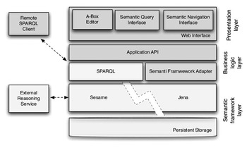
NavEditOW is an environment for navigating, querying and A-Box editing of OWL ontologies (up to OWL-DL) through a web-based interface. An overview of the NavEditOW architecture is shown in Figure 2. In the following paragraphs, we present more details about each of these three basic functionalities supported by the application.
An overview of the NavEditOW architecture

Navigation. With the ontology navigation interface the users can view ontology individuals and their properties and browse properties via hyperlinks. Browsing the ontology is essential for the user in order to explore the available information and it also helps non-expert users to refine their search requirements when they start with no specific requirement in mind (Ram & Shankaranarayanan, Reference Ram and Shankaranarayanan1999). The hierarchical organization of the different concepts and individuals of the ontology is graphically represented as a dynamic tree. The aim of the navigation tree is to explore the ontology, and to view classes and instances to discover the relation between them. The tree does not only represent a hierarchy of classes connected with isA binary relations (like the navigation tree of Protégé), but also represents tree-like connections of individuals for domain-dependent classes of properties (e.g. partOf, isLocatedIn and so on). From a formal point of view, ontological relations supporting tree-like visualization (tree-like properties) are those represented as not symmetric properties and whose inverse is functional (therefore identifying directed acyclic graphs). These properties directly link an individual with its ‘father’ and are particularly relevant with respect to mereological relations (e.g. partOf, composedOf), and to relations defining hierarchical spatial and temporal structures (e.g. representing the unfolding of historical periods). Another kind of relations exploited for the visualization is relations defining total orders on individuals (e.g. isFollowedBy).
The root of the navigation tree is the OWL class Thing, and the rest of the tree is organized as follows: under the root node, there are the top-level classes (i.e. direct subclasses of Thing); each class can be expanded to show its subclass hierarchy and its individual members; individual-to-individual tree connections are defined according to a number of selected tree-like properties (e.g. partOf); finally if the total order relations are selected, they are exploited to order individuals within a given level of the tree. In order to distinguish between classes and individuals, they are represented by means of different colors in the graphical user interface.
Editing. The application allows the users to create, edit and delete individuals, their properties and their labels from the ontology. In fact, to ensure multi-languages support, it is possible to define several labels in different languages for every individual. Users can also create new individuals related to an existing one by means of tree-like properties (e.g. partOf): the new individuals are immediately displayed in the navigation tree under their ‘father’.
The properties of each class are defined in the T-Box. Two types of properties are distinguished: object property is a binary relation between two individuals and datatype property is a binary relation between an individual and a literal (a primitive type, like string or number). Cardinality and range restrictions for properties are used to support users while editing.
There are a datatype and an object editor in the framework: the datatype editor allows for editing literal values displayed as a text input box; the object editor allows for defining the property values by presenting a selection tree to the user; the individuals displayed in the tree are only those that are valid for the property range.
Querying. The first implemented query interface is the SPARQL query form in which users can write a query in the SPARQL language, display results in paginated tabular form and navigate through results via hyperlinks. This interface is very flexible because the users can write arbitrary queries, but it is not suitable for end users. Another kind of query interface is based on a predefined set of queries. Every predefined query is composed of a description in natural language, a SPARQL query with eventually free parameters and a list of parameters. Every parameter has a label, a type and eventually a restriction on the valid values (e.g. a parameter can be filled only with instances of a specific class). For this interface, users can select a query by its description, fill the query parameters and execute it. The results are presented as the results of the other query form. A future extension of this query mechanism may adapt the query with reference to the number of retrieved results.
5 Formalization of the upper-level functional design ontology
In the engineering design context, a functional perspective permeates different expert practices and the knowledge involved in these practices.
The UFDO represents the domain knowledge about the objects to be designed as well as the ‘social knowledge’ about the actors involved in the design and production process. UFDO has been represented in OWL-DL, which corresponds to the SHOIND Description Logic. For the Description Logic syntax and semantics, we refer to Baader et al. (Reference Baader, Calvanese, McGuinness, Nardi and Patel-Schneider2003). The ontology consistency has been checked with the DL reasoner FACT++ (Tsarkov & Horrocks, Reference Tsarkov and Horrocks2006)Footnote 3.
The top-level concepts of the UFDO are: DesignObject, Function, StructuralParameter and DesignActor.
5.1 The functional and structural mereologies in design objects
The representation of the design objects is based on a functional perspective and concerns two kinds of knowledge about them: (i) behavioral and teleological knowledge (functional knowledge); (ii) structural knowledge. Behavioral knowledge concerns the behaviors of design objects while the teleological one concerns the goals assigned to these behaviors. In other words, behavioral knowledge involves competencies regarding the physico-mathematical models ruling the design object behaviors, and it is mandatory for establishing the design object structure. On the other hand, teleological knowledge involves competencies for connecting a specific design object behavior to its proper mission. Teleological knowledge copes with the selection of the useful design object behavior, which is able to satisfy the design object goals, while behavioral knowledge regards the synthesis of design object structure. In this ontology they have been condensed into a functional representation providing a qualitative representation of functions under the top-level Function.
Structural knowledge concerns a qualitative mereology representing the design objects according to their specular functional organization—under the top-level concept DesignObject—and a quantitative representation of a number of structural parameters—under the top-level concept StructuralParameter.
The knowledge about functions is represented through a functional decomposition, that is, a hierarchy of functions organized along the binary relation needA. A function f 1needA function f 2if and only if f 2needs to be performed in order to properly carry out f 1. At the top of the hierarchy there are the ‘Top Functions’ (TopFunct), that is, functions that are not needed by any other functions; at the bottom there are the ‘Ground Functions’ (GroundFunct), that is, functions that do not need any other function; any other function in the ontology refers to the class of ‘Sub Functions’ (SubFunct), that is, functions that may need some other lower-level functions and that are needed by higher-level functions.
On the other hand, ‘Design Objects’ are basically organized in a mereology by means of the partOf binary relation (and its inverse hasPart); elements of this mereology are identified according to functions, and therefore we will refer to it as a functional mereology. The functional mereology unfolds specularly with respect to the functional decomposition organization: with the ‘Top Functional Systems’ (TopFSys) on top, ‘Sub Functional Systems’ (SubFSys) in the middle and ‘Ground Elements’ (GroundElement) at the bottom layer. The partOf relation has been axiomatized to be not transitive in order to trace direct mereological connections; instead, in order to exploit inference about transitiveness when needed, a new relation partofTransitive has been introduced as the transitive closure of the partOf.
The functional decomposition and the functional mereology are connected first through the binary relations hasA and perform (the inverse of the first one: hasA– = perform). Each DesignObject is therefore designed in order to perform one and only one specific function, as stated by the following range restriction:

This relation between the design object mereology and the functional decomposition is so strong that design objects belonging to a specific class in the mereology can be defined on the basis of the function they perform according to the following axioms:



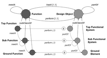
In this way it is possible to exploit inferential power in order to infer that design objects are of the subclasses TopFSys, SubFSys or GroundElement according to the function they are associated to. Obviously, it could be possible to specularly make the same assumptions on functions, even if in this project the perspective of starting from information about function decomposition to infer information about object classes seems more useful to domain experts. Figure 3 represents such logical dependencies (the arcs represent universal restrictions if it is not explicitly stated that the restriction is existential; for the sake of clarity, full names are used in the pictures instead of the abbreviations used in the DL formulas).
The figure depicts the functional decomposition in upper-level functional design ontology, and the specular mereological arrangement of design objects

5.2 The ‘fill’ and ‘remove’ perspective on design objects
Besides the mereological perspective described above, there is another relevant function and object classification in this context. According to the functional perspective on the design object mereology, both functions and design objects can be classified on the basis of the role they play in the design process. One of the outstanding traits that characterizes the design activity consists of a progressive configuration of functional building blocks (i.e. design object parts) put together in order to achieve a complete artifact aligned with the end user requirements. During this process, designers ideally start from some parallelepiped and give a form to the design objects by adding or removing portions of matter. Once a geometrical entity (e.g. a parallelepiped) has been defined according to the functions it has to carry out, it is then assembled together with other functional building blocks until the design object is a complete whole. Thus, the design object parts can be conceived as aggregates of geometrical entities, each playing a different role in the iterative building of a single functional feature. A peculiar tract of the UFDO presented here is the treatment of these distinctions in the ontology. Some geometrical entities are conceived of as fillers of the design object parts while some others are thought of as space to remove from matter.
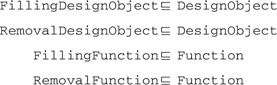
In order to take into account the different roles that design objects can play in the design process, the two disjoint subclasses of function ‘Filling Function’ and ‘Removal Function’. On the counterpart, ‘Filling Design Objects’ and ‘Removal Design Objects’ need to be represented. These relationships between different types of functions (filling and removal) and types of design objects need to be analyzed and formalized; such relationships are not trivial, since the mereological structure of objects is relevant for the function they can actually perform.
In particular, a filling design object is designed to perform only a filling function, while a removal design object is designed to perform only a removal function:

5.3 Integrating the two perspectives on the design objects representation
The classification of functions according to the proposed functional decomposition and the classification of functions according to their role in the design process intersect in the following way: filling functions can be top, sub and ground functions; removal functions are only ground functions (i.e. they do not need any other functions in order to be properly carried out) and, as a matter of fact, they are associated only with ground elements. The following restrictions are therefore imposed on the UFDO:

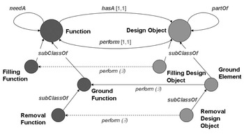
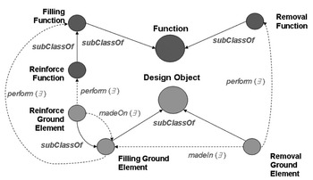
Figure 4 provides a graphical representation of the connections between the ‘fill’ and ‘remove’ perspective and the mereological perspective on the representation of objects and functions. As said before, the functional decomposition is based on the needA relation that represents basic functional dependencies. Moreover, functions are connected to design objects by means of the hasA, perform relations.
The figure depicts the relationship between filling and removal functions in upper-level functional design ontology

According to the nature of the design process previously introduced, the ground elements represent the building blocks of the subfunctional systems that are gradually configured during the design process. However, these building blocks cannot be purely conceived as entities without parts. They are, in fact, subjected to a process of addition and subtraction of matter, according to the proper function they have to carry out. For this reason, we introduced the ground elements subdivision in the UFDO in ‘Removal Ground Element’ and ‘Filling Ground Element’ as follows:

On the basis of the introduction of these entities, it is possible to specify further kinds of ground elements, that is, the ‘Interrupted Ground Element’ that intuitively represent ground elements which have been excavated in different shapes in order to fulfill their function. Here below, the axiom representing this concept is presented.

Note that in the above formula we have introduced the madeIn relation in order to express the mereological relation holding between a GroundElement and the RemovalGroundElement (e.g. an oval shaped hole), where the second one is part of the first one. According to the intuitive meaning held by any removal activity within the engineering design process, we exclude the case that a removal ground element could be also applied to a removal ground element. As a consequence of this assumption, in the InterruptedGroundElement definition we assert that a ground element, which is an interrupted ground element, can never be a removal ground element.
On the other hand, it is well known to design experts that whenever a subtraction of matter is applied to a component actively performing some function, a reinforce must be done. For this reason the ‘Reinforce Ground Element’ concept has been introduced as follows:

Nonetheless, this definition has been exploited to define the ‘Reinforced Ground Element’ concept, that is, a ground element ‘made on’ another ground element.

As for the madeIn, the madeOn relation must also be conceived as a mereological relation living between the ReinforcedGroundElement and the ReinforceGroundElement, where the second one is part of the first one. These relationships are represented in Figure 5. Even if it is beyond the purposes of this paper to proceed further with the analysis of the relationships holding between reinforced ground elements and interrupted ground elements, it is useful to note that a large part of the creativity in design depends on them.
The figure depicts the relationships among reinforce, removal and filling design objects and the functions they perform

As for the physical characteristics of design objects, UFDO considers a set of ‘Structural Parameters’ (e.g. Weight, Volume, Chemical Composition) that a ground element has to satisfy in order to meet the specifications of the actors involved in the design process. The concept of StructuralParameter is therefore strictly related to the representation of the knowledge corpus concerning the social collaborative environment in which the design process takes place.
5.4 Actors involved in the design process
Along with the representation of functions and design objects we therefore need to represent knowledge about the actors involved in the design and production processes: the ‘Design Actors’. Specifications of the DesignActor concept are relative to the ‘Management’, ‘Engineer’, ‘Client’ and ‘Manufacturer’ actors. According to the collaborative nature of the design process, the design actors take part in the process by prescribing specific requests on the design objects.
This commitment of actors in the definition of design objects is represented by means of the relation prescribeA connecting DesignActor (the domain of the relation) to DesignObject (the range of the relation). In particular, we observe that: (i) Engineer and Client prescribe on GroundElement and on SubFSys, (ii) Manufacturer has no prescribing role and (iii) only Management has a prescribing role on TopFSys. This is stated by the following axioms:


The prescribeA relation represents the general commitment of actors to the definition of a design object. However, with respect to ground elements, this role can be more detailed, involving specification on the structural parameters for these objects. This association is represented by means of the role define, which is restricted to have DesignActor as its domain and StructuralParameter as its range. As one expects, a design actor defines the structural parameters of those design objects with respect to his/her prescriptive role (see the above axioms).
Two other relations are introduced in order to explicate the behavioral and structural constraints that exist among the different design object parts. These relations explicitly represent what kind of side-effects one has to consider when a prescription on structural parameters is stated. More precisely, the imposeA relation, linking structural parameters to structural parameters, expresses the condition in which a prescription on structural parameters of an object is mandatory with respect to a prescription on the structural parameters of another object; the conflictWith relation, linking structural parameters to structural parameters, expresses the fact that a prescription on structural parameters of an object can obstruct the structural parameters of another object.
Usually it is interesting to consult the ontology about this kind of relation, whenever the involved objects are designed and produced by different actors in the process.
Finally, along with the actors directly involved in the design process, we introduce the concept Business. This concept includes all the businesses that are involved in the manufacturing process. A Business is therefore connected with the DesignObject that it constructs by means of the role make. The different kinds of DesignActor are connected to Business by means of the role memberOf. In order not to define a complex ontology of businesses from scratch, we exploit the semantic Web approach, importing an existent ontology of businesses, namely the ‘eBiquity Contact Information Ontology’, developed by the UMBC eBiquity Research Group (University of Maryland, Baltimore County)Footnote 4. In this way, the UFDO can store business contacts according to standards of business cards.
6 Case study: supporting knowledge management for the design and manufacturing of a supermotard bike
This functional ontology was the starting point for building a system to support I-TEA management and mechanics for the monitoring of different manufacturing phases: in this way, a model shared among all partners of the Terra Modena 198 is provided. Differently from past experiences (e.g. Bandini et al., Reference Bandini, Colombo and Sartori2005; Bandini & Sartori, Reference Bandini and Sartori2006), the functional ontology was not used to guide the process of acquiring and representing procedural and experiential knowledge, but as the heart of a semantic Web application that helps the network of partners in taking care of possible problems in project management. Further details about how this was possible are given in the next section.
6.1 The Terra Modena domain ontology
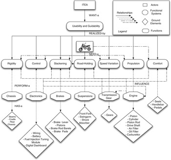
Formally, the Terra Modena domain ontology is a specialization of the UFDO presented above. The domain ontology basically introduces a number of instances to represent specific functions and design objects. Some domain-related attributes have been inserted to describe structural parameters. In the rest of the paper, we use a hybrid linguistic notation: UFDO has been formalized in English and the UFDO terms are written according to their English form; on the contrary, since the main actors of the project were Italian, the domain ontology has been represented using Italian terminology in the prototype; however, Figure 6 provides a graphical representation of the ontology in English terminology.
The functional ontology of Terra Modena 198 motorbike

Observe that the domain design objects and functionalities are represented with A-box statements. Hence, the users of the application can add or delete functions and design objects of interest through a Web-based interface, according to the functionality offered by NavEditOw and discussed in Section 4.
As introduced in Section 2 the top functional systems consist in the Supermotard bikes; the subfunctional systems (e.g. the Engine, Brakes, Chassis) are aggregate components that perform the subfunctions of a motorbike (e.g. the Propulsion, Slackening, Road-Holding), and the ground elements are atomic ingredients of these aggregate components (e.g. the Pistons, Handlebar, Swingarm). The second layer from the top represents the set of subfunctions needed to achieve the top-level function (represented in the top layer). These functions are linked to the design objects, that is, subfunctional systems, performing these functions. These subfunctional systems are connected to the set of ground elements they are composed of.
6.2 Semantic queries and inference with the Terra Modena domain ontology
The formal representation given in the UFDO supports the representation of knowledge involved in the motorbike design and manufacturing processes along different directions.
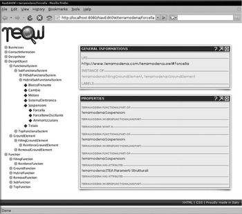
First, the representation allows to build applications around a strong model of the knowledge behind the activities carried out by the stakeholders involved in the design and manufacturing of the motorbike; that is, to say that it allows a shared common view on different specific purpose applications. The semantic Web-based application allows to browse the knowledge represented providing a unified view on the overall knowledge related to the motorbike. For example, one can navigate through functions and discover which objects are designed to perform these functions. The motorbike components can be accessed by browsing the navigation tree; their properties can be visualized. Observe that the NavEditOw functionalities are exploited in order to provide a structured visualization of instance dependencies along the partOf relation. Figure 7 provides an example where the ‘sospensioni’ subfunctionalSystem is expanded and the properties concerning the ‘forcella’ ground element are shown.
The navigation of the ontology tree

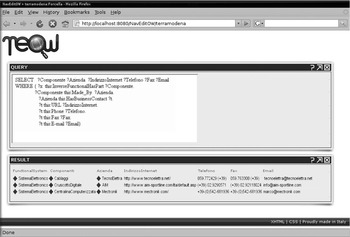
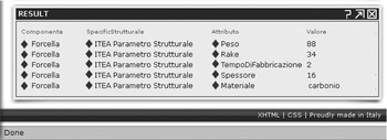
Second, standard query languages such as SPARQL can be exploited to retrieve information according to the semantic model provided. SPARQL queries can be easily parameterized in order to provide users with user-friendly interfaces supporting the discovery of knowledge about specific object of interest. As an example, when a problem concerning subsystem occurs, often it is not easy to recall all the partners involved in the manufacturing of such a subsystem. With a simple parameterized SPARQL query, it is easy to retrieve all the elements a subsystem is composed of and to present contact information about the businesses involved in the provision of the components. Figure 8 shows that this information can be retrieved on the basis of the ontological model. Figure 9 shows results of a parameterized query related to the structural parameters of ground elements, that is, ‘forcella’ in the picture.
Supporting the semantic-based retrieval of information about the components of a subfunctional system

Information about the structural parameters of the component ‘forcella’

Third, automated reasoning techniques can be used. The reasoner completes knowledge inserted by users exploiting concept definitions. As an example, membership of design objects to classes is inferred on the basis of the axioms (1), (2), (3). Given a component of the motorbike together with its associated functionality, one can infer what kind of component this is, and therefore, what the mereological structure in which it is embedded is, what the design actors prescribing it are and, finally, how it is possible to optimize the whole production process in which the component is involved. Formally, the following statements are contained in the Terra Modena Knowledge Base:

Then, from axiom (2) one can infer that SubFSys(cambio001), that is, the cambio001 component is a subfunctional system, thus having parts performing specific ground functions.
SPARQL queries can fully exploit the semantic-based approach to knowledge representation. In fact, it is possible to combine reasoning performed by state-of-the-art reasoners (we used FACT++) with queries, and answering queries on the basis of the inferences performed. As an example, all the subcomponents of the motorbike can be retrieved since the reasoner completes the extension of the partOfTransitive relation.
7 Conclusions and future works
In this paper, we have presented a framework for the development of decision support systems in the engineering context. This framework is based on the development of functional ontologies to describe all the properties of a product. Once these ontologies are defined, opportune functionalities of the system can be designed and implemented.
Moreover, an application of this framework for the design of a KM system to support a network of SMEs in the manufacturing of a supermotard bike has been introduced: starting from a shared, conceptual and well formalized model of the final product it has been possible to support the different partners in the networked enterprise to clearly define their role in the motorbike lifecycle, with great benefits from both the project management and product design and manufacturing perspectives.
Future works are devoted to exploiting the design of more complete architectural solutions, centered on the knowledge model involved. In particular, a database supporting the supply-chain and order management could be semi-automatically designed starting from an ontological knowledge model. In fact, in some networks of SMEs, the level of ICT adoption is so poor that no database supporting order and supply-chain management is adopted. This is the case, for example, of the Terra Modena network. In such a scenario, the reuse of existent ontological models and the exploitation of semantic Web technologies coupled with standard data management applications can provide simple but flexible solutions to support SMEs in E-Manufacturing.
Acknowledgement
Part of this work is extracted from the Gianluca Colombo’s PhD Dissertation, Representing and Managing Designers and Engineering Core Knowledge: Ontological and Procedural Knowledge Integration, University of Milan—Bicocca. Authors wish to thank Gianluca for his contribution.