I. INTRODUCTION
Microstrip patch antennas are extremely attractive candidates for uses in many wireless applications due to their interesting features, such as compatibility with monolithic microwave-integrated circuit (MMIC), light weight, small volume, low-cost device, low profile, stable radiation, and easy fabrication. On the contrary the narrow bandwidth is a major obstacle associated with a microstrip antenna in wide band applications. So, the impedance bandwidth of the basic structures of the microstrip antennas is only a few percent 2–5% [Reference Majid, Rahim, Hamid and Ismail1–Reference Makarov and Iyer2]. Therefore, the needs of broadband antennas have pushed research efforts to meet the development of the antenna structure broadband or the improvement of the frequency bandwidth to support multiple wireless system application, especially for applications of multimedia communications and wireless radio technologies to greater capacities broadband service.
Several ways to enlarge the operating bandwidth frequency have been studied [Reference Cao, Zhang, Liu, Yu, Guo and Wei6–Reference Khidre, Lee, Yang and Eisherbeni13]. In this work, a novel rectangular broadband antenna design with the improvement of the bandwidth is proposed. Design and conception methodologies allow us to achieve a rectangular antenna which radiates in the desired broadband frequency range. The proposed antenna consists of a slot and a matching coplanar waveguide (CPW)-fed. The CPW mechanism, geometry antenna, and slot techniques also have many advantages over microstrip type to efficiently control the characteristics of the impedance, and to ease the integration with active devices. The details of the design considerations for achieving broadband antenna and both simulated and experimental results are presented and discussed.
II. ANTENNA DESIGN
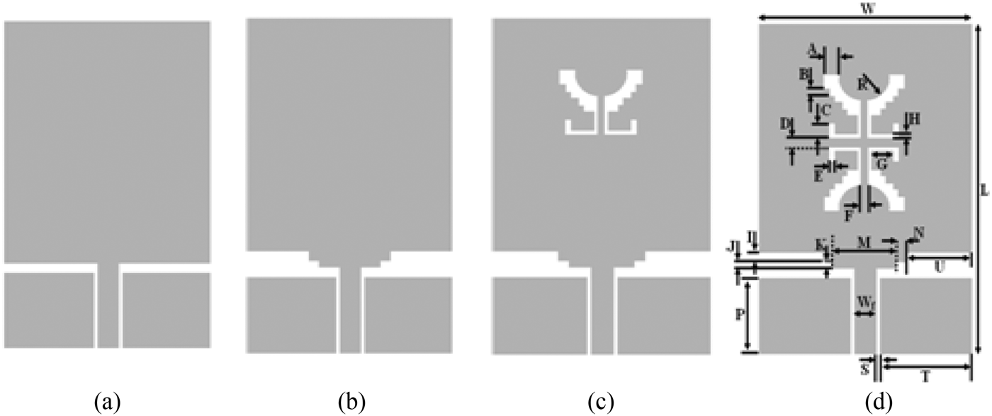
The geometry and configuration of the CPW-fed slot rectangular antenna is shown in Fig. 1(d). The proposed antenna is implemented on a low-cost FR4 substrate with a relative permittivity ε r = 4.4, thickness of h = 1.6 mm, and total area of 27 × 42 mm2. The rectangular microstrip antenna is fed by using a 50 Ω impedance CPW that has a central strip having as width W f = 3.2 mm, the gap between the central feed line and the ground is fixed at S = 0.25 mm. The optimization parameters design is done using momentum electromagnetic software integrated into Advanced Design System (ADS), which contains different techniques and calculation methods [14]. For comparison, we have conducted another study using CST Microwave Studio in frequency domain where the numerical analysis is based on FIT [15]
Design evolution of the final proposed antenna.

The final dimensions of the antenna structure are listed in Table 1.
Optimized dimensions in mm.
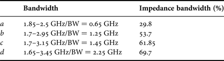
The aimed goal of this study is to widen the narrow bandwidth of the basic rectangular patch antenna to covering wideband applications using the optimization and miniaturization techniques integrated into ADS. Therefore, the first step in designing the CPW-fed rectangular antenna with a bandwidth of 600 Mhz as shown in Fig. 2(a). Secondly, cutting a symmetrical periodic rectangular edges have effect on the enhancement of the input impedance bandwidth of the antenna as shown in Fig. 2(b), it can be seen that the return loss was improved. The slot geometry on the radiator patch is another critical design parameter influencing the antenna characteristics. Figs 2(c) and 2(d) show the return loss curves for variation of a symmetrical curved-shaped slot. The final circuit is operating in a large frequency band between 1.7 and 3.5 GHz. It is clear that the improvement of the input impedance bandwidth is due to the presence of the slot notched and the cutting edges. The simulated values are given in Table 2
Simulated return loss results versus frequency in ADS.
The bandwidths of the proposed antenna for different structures.
.
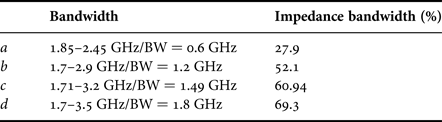
For the comparison of the following results, we have made another simulation using CST Microwave Studio. After the simulation, the following results are shown in Fig. 3 and Table 3, respectively. In Figs 2 and 3, it is clearly observed that simulation results on ADS and CST are the closest agreement. A slight difference in the two simulated values is potentially due to the fact that they are based on two different solving algorithms and meshing techniques, it is basically because of the two different numerical methods employed, i.e., MoM by the ADS and FIT by the CST Microwave Studio.
Simulated return loss results versus frequency in CST.
The bandwidths of the proposed antenna.
The bandwidth impedance in terms of VSWR is presented in Fig. 4 for the different steps the conception of the antenna structure. The variation of the final proposed antenna gain versus frequency is plotted in Fig. 5. For current distribution it is presented in Fig. 6.
VSWR versus frequency.
The gain versus frequency.
Simulated surface current distributions of the proposed antenna at (a) 1.8, (b) 2.4, and (c) 3.2 GHz.
The simulation radiation patterns of the proposed antenna are presented in Fig. 7 at 1.8, 2.4, and 3.2 GHz in the Phi = 0° and Phi = 90° planes.
2D simulated radiation pattern at 1.8, 2.4, and 3.2 GHz of the proposed antenna.
ACHIEVEMENT AND MEASURMENT RESULTS
After the study of the bandwidth enhancement of the narrow bandwidth rectangular antenna using ADS and CST, the final prototype of the investigated broadband antenna structure has been achieved using LPKF machine. The photograph of this antenna is shown in Figs. 8 and 9. The experimental results are done on Vector Network Analyzer (VNA R&S@ZVB20 from Rohde & Schwarz). The simulated and experimental results of the return loss are in good agreement as shown in Fig. 10. This allows the validation of the broadband antenna structure with frequency band from 1.7 to 3.5 GHz which corresponding 69.7%, compared to the narrow band of a classic rectangular patch antenna, which meets the bandwidth requirement for wideband applications such as UMTS, WLAN, WIFI, WMAX, and RFID.
Photograph of the fabricated structure with LPKF machine.
Photograph of the achieved broadband antenna.
Comparison of simulated and measured return loss.
The measured radiation patterns in E- and H-plane at 1.8, 2.4, and 3.2 GHz are presented in Fig. 11.
Radiation pattern at (a i) 1.8, (b i) 2.4, and (c i) 3.2 GHz.
IV. CONCLUSION
This work has presented a study of a new low-cost coplanar broadband antenna structure using slot technique for bandwidth improvement. The measurement and simulation results are in agreement which validated the rectangular antenna CPW-fed new structure with a bandwidth of 1800 MHz. This achieved antenna is feed with CPW line which is easy to be integrated with passive and active printed circuits broad component for multiple wireless applications such as UMTS, WLAN, WIFI, WMAX, and RFID.
ACKNOWLEDGEMENTS
All authors would like to thank DICOM Laboratory in University of Cantabria and Microwave Group in ESEO France, for providing support and assistance to perform simulations using softwares and measurements on the VNA and Anechoic chamber.
 R. Dakir was born in 16 February 1982. He received his Master's degree in Science of Computer and Systems from the FST University of Hassan 1st in Settat, Morocco. He is currently a Ph.D. student in FST university Hassan 1st Settat, Morocco. He is involved in the design of microwave hybrid circuits and antennas.
 J. Zbitou was born in Fes, Morocco, in June1976. He received his Ph.D. degree in Electronics from the University of Nantes, France, in 2005. He is currently a Professor of Electronics in FPK University Hassan 1st Settat, Morocco. He is involved in the design of hybrid, monolithic active, and passive microwave electronic circuits.
 A. Mouhsen was born in May 1960. He received his Ph.D. degree in Electronics from the University of Bordeaux I, France. He is currently a Professor of Electronics in FSTS University Hassan 1st Settat, Morocco. He is involved in the design of hybrid, active, and passive microwave electronic circuits and digital systems.
 A. Tribak was born in Larache, Morocco, in 1981. He received his M.Sc. degree in physics from Abdelmalek Essaadi University, Tétouan, Morocco, in 2006. He received his Master's degree in Communications Engineering from the University of Cantabria, Santander, Spain, in 2008, and received his Ph.D. of Telecommunication degree in 2011, from the University of Cantabria, Santander, Spain. Since 2006 to 2011, he has been with the Department of Communications Engineering, University of Cantabria. Since 2011 he is a Professor in the National Institute of Poste and Telecommunication, Rabat, Morocco. His main areas of activities are microwave circuits and systems, and antenna feed subsystems for satellite and radio-astronomy applications.
M. Latrach was born in Douar Ksiba, Sless, Morocco, in 1958. He received his Ph.D. degree in Electronics from the University of Limoges, Limoges, France, in 1990. He is currently a Professor of microwave engineering with the Ecole Suprieure d'Electronique de l'Ouest (ESEO), Angers, France, where his research involves RF and microwaves. His fields of interest are the design of hybrid, monolithic active, and passive microwave circuits, metamaterials, LH materials, antennas and their applications in wireless communications, and wireless power transmission.
A. M. Sanchez was born in Santander, Spain, in 1955. He graduated in 1978 and received the Doctor of Physics (Electronic) degree with honours in 1983, both from the University of Cantabria, Santander, Spain. From 1980 to 1983 he was Ingenieur Stagiere at THOMSON-CSF, France. He is currently head of the Communications Engineering Department at the University of Cantabria. He has a wide experience in the analysis and optimization of nonlinear microwave active devices. His research interests are nonlinear MESFET/HEMT and HBT device modelling with special application to the large signal computer design and new waveguide structures for antenna feed systems.