Introduction
In recent years, sparse array has been widely used to optimize the beamforming in antenna array design [Reference Cen, Ser, Yu and Rahardja1–Reference Reyna Maldonado and Panduro15]. Sparse array is obtained by reducing the number of radiating elements in an array. Compared to periodic array with the same aperture, sparse array can save a large amount of elements, significantly decreasing the manufacture cost and system complexity.
In addition to the element number, the distance between adjacent elements is a critical factor to consider. In certain applications, the dimensions of elements and the required spacing between them necessitate an inter-element distance larger than half of wavelength (0.5λ). Beyond this threshold, grating lobes are generated, leading to power dispersion and interference in undesired directions [Reference W. Alshrafi, Bassam and D. Heberling16–Reference Bogaerts, Dahlem, Dwivedi, Jansen and Rottenberg18]. Consequently, distributing an array with a periodic configuration without the presence of grating lobes becomes unfeasible when the inter-element distance exceeds 0.5λ.
To address these challenges, sparse arrays offer a solution by allowing for the use of larger inter-element distances in array design without the occurrence of grating lobes. Various optimization techniques have been proposed, including particle swarm optimization (PSO) algorithm [Reference Chen, Dong, Jiao and Zhang19], genetic algorithm (GA) [Reference Kwon, Park, Kim and Hwang20, Reference Enache, Deparateanu, Enache and Popescu21], and Convex optimization [Reference Yang, Young, Dong and Myung22, Reference Dong, Li, Tan, Hu and Jiang23]. Through optimization of the element distribution, the peak-side-lobe-level (PSLL) of the array can be effectively minimized, while the grating lobes can be suppressed. However, the inter-element distance is still maintained not above the wavelength. Therefore, more investigations should be done for the situations where the inter-element distance is above the wavelength.
In addition to the aforementioned optimization algorithms, an alternative approach involves initially establishing a random element distribution in the array and subsequently adjusting the positions of elements. This process continues until the desired side-lobe-level (SLL) for the entire antenna array is achieved. Then the adjustment of element positions ceases.
In this paper, a two-dimensional (2D) sparse array is proposed employing Delaunay Triangulation coupled with Convex optimization. Delaunay Triangulation algorithm is utilized to distribute element positions, and Convex algorithm is utilized to optimize element excitations. What is more, the array maintains a minimum inter-element distance of up to 8λ, yielding a PSLL of −17.3 dB in 180 planes. Furthermore, this array can achieve beam steering with good performance within a field-of-view range of 80°.
Compared with some existing sparse array designs, there are several benefits and advantages for the design in this paper. First, some traditional methods, such as GA in paper [Reference Kwon, Park, Kim and Hwang20] and PSO algorithm in paper [Reference Chen, Dong, Jiao and Zhang19], always work on arrays with smaller inter-element distance (not beyond half of wavelength). The main purpose of the designs is to decrease the element number. When the inter-element distance is beyond half of wavelength, these methods cannot prevent the appearance of grating lobes. However, our design can obtain radiation pattern with no grating lobe and low SLL when the minimum inter-element distance is as large as 8λ. Second, low PSLL is another advantage of this design. The PSLL in this paper is suppressed to lower level of −17.3 dB, compared with the design with a smaller minimum inter-element distance of λ in paper [Reference Alidoustaghdam, Kokkeler and Miao24], which owes a PSLL of −7.5 dB. The combination of the Delaunay Triangulation and Convex optimization provides more flexibility in the suppression of both SLL and grating lobes, due to the optimization on both array configuration and element excitations. Third, the Delaunay Triangulation algorithm can generate a desirable sparse configuration using significantly less computation and time, compared with the complex design process in papers [Reference Zhang, Bai, Zheng and Zhou25, Reference Mo, Tong, Wang, Wang, Luo and Li26]. Besides, wide beam steering is an additional advantage of this design method.
Submission proposed algorithm for sparse array design
Array configuration with Delaunay Triangulation algorithm
According to antenna theory, the radiation pattern of the antenna array is defined by element pattern (EP) and array factor (AF). Consider a planar antenna array with M× N identical elements, with identical amplitude and initial null phase.
Assuming the EP is f(θ), the radiation pattern of the planar array can be obtained from the multiplication of AF and EP. The radiation pattern can be expressed as follows:
 \begin{align}
& E(\theta ,\phi ) = \sum\limits_{m = 1}^M {} \sum\limits_{n = 1}^N {} {\alpha _{m,n}}\exp \{\, j[(m - 1)(k{d_x}\sin \theta \cos \phi ) \\ & \qquad\quad\quad + (n - 1)(k{d_y}\sin \theta \sin \phi )]\} f(\theta )\nonumber\end{align}
Here, dx and dy are the inter-element distances in x- and y-axis, respectively; k = 2π/λ is the wave number at the working wavelength λ. αm,n represents the excitation of the element in mth position in the x-direction, and the nth position in the y-direction. The excitation of all elements is denoted by a vector:
 \begin{equation}{\boldsymbol{\alpha }} = {({\alpha _{1,1}},{\alpha _{1,2}},\ldots\ldots,{\alpha _{m,n}},\ldots\ldots,{\alpha _{M,N}})^T}\end{equation}
The PSLL is defined in equation (3), where θ 0 is the main beam angle:
 \begin{equation}PSLL = {\text{max}}\left\{ {\left| {E\left( \theta \right)/E\left( {{\theta _0}} \right)\,} \right|} \right\}\end{equation}
The array distribution design is accomplished by a controlled random movement of elements. In the beginning, the initial points with the specified number are randomly generated within the required square region. Then boundary points are defined and interpolated to form a smooth boundary. The repulsion mechanism is applied iteratively to prevent the points from becoming too close, adjusting their positions based on the repulsive force calculated from the Delaunay triangulation and distances between points. The configuration of the elements adheres to the constraint of the minimum inter-element distance, hence termed a pseudorandom configuration. The positions of elements are updated each time in the loop based on the repulsion force. Finally, the updated positions of elements are plotted, generating the sparse array configuration.
Delaunay Triangulation is a geometric algorithm for dividing a set of points in a plane into a non-overlapping triangle mesh that satisfies a specific optimality criterion [Reference Delaunay, Vide, Lamémoire and De Georges27]. The Delaunay Triangulation of a set of points has the property that no point lies within the circumcircle of any triangle in the mesh. The key characteristic of Delaunay Triangulation is that it maximizes the minimum angle of all the triangles in the mesh, leading to more regular and well-conditioned triangles. This property makes Delaunay Triangulation desirable in certain applications, due to more geometrically favorable triangular meshes produced.
To construct a sparse array, Delaunay Triangulation is applied to establish a mesh or connectivity structure for the populated elements in an array. The points representing elements are linked in a manner uploading the empty circumcircle property. This strategy leverages the inherent property of Delaunay Triangulation, including the optimal triangle quality and the assurance of geometrically advantageous connectivity between these elements.
Delaunay Triangulation can maximize the minimum angle of all the angles and minimize the edge length variance in the triangles, which are composed by any three points in the array plane. This leads to more uniform spacing between the element positions. It can ensure that the groups of points in the array plane are not tightly packed. Therefore, the distribution of elements can be ensured to meet the requirement of minimum inter-element distance.
Excitation optimization with Convex algorithm
Based on the sparse distribution obtained from the Delaunay Triangulation in the first step, Convex optimization [Reference Boyd, Boyd and Vandenberghe28] is utilized to optimize the excitations of the elements in this sparse array.
Convex algorithm is utilized to minimize the norm of the excitation vector, l1-norm. This method is based on compressive sensing theory, aiming to minimize the number of samples to reconstruct a signal. In this optimization process, a desired mask level MaskLevel is proposed as the additional constraint for selection of proper solutions. In details, the program performs continuous iterations until the SLL reaches the mask level.
 \begin{equation}\begin{gathered}
\quad \text{min}\|\boldsymbol{\alpha}\|_{1}\\
\quad \quad \quad \quad E({\theta _0}) = 1 \hfill \\
subject\,\,to\;E \leq {10^{MaskLevel/20}} \hfill \\
\end{gathered} \end{equation}
In the initial array distribution, all elements are excited with a value of 1. Here, SDPT3 solver is applied in Convex algorithm. SDPT3 solver is one of the default solvers in Convex, which supports all the continuous (non-integer) models. With this solver, in the Convex optimization, the excitations of elements are allowed to be non-integer value. Subsequently, after Convex optimization on the element excitations, a new set of excitation values is generated. The positions of the elements in the array remain unchanged from the initial configuration.
Procedure of the hybrid algorithm
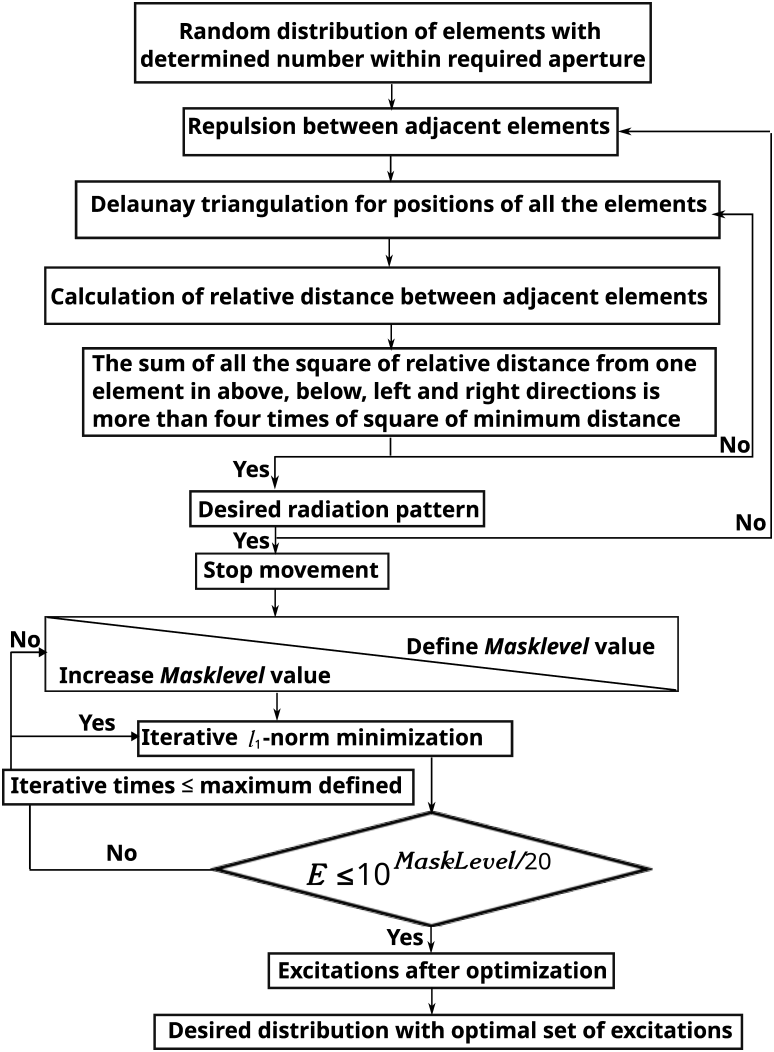
Figure 1 presents the flow diagram of the design process. By employing the Delaunay Triangulation algorithm, the positions of the elements are adjusted while adhering to both the minimum inter-element distance and the desired radiation pattern constraints. In this workflow, Delaunay Triangulation plays a crucial role in managing point repulsion, ensuring that the points are adequately spaced and not too proximate to one another. Once the optimal element position set is achieved, the adjustment of element positions within the array ceases. Then, Convex algorithm is operated on the excitation vector of these elements. In the beginning of the optimization process, a certain value of the PSLL is defined and tried with this optimization algorithm. If no solution is found after the maximum iteration time, the PSLL value is changed to another one. Until the radiation pattern fitting the given mask is obtained, the optimization process ceases. Finally, a sparse distribution and an optimal set of excitations of elements are achieved by this hybrid optimization.
Flow diagram of the sparse array design.

Array configuration and radiation pattern
In the antenna array, each element is a broadside antenna, whose maximum radiation directs normal to the axis of the array. We assume the radiating pattern of each element (EP) is Gaussian pattern with a full-width at half-maximum of 75°.
In this configured array, the desired half-power beam width (HPBW) of the main lobe is set at 0.3°. The square planar array spans a length of 169λ. In a periodic array with an inter-element distance of 0.5λ, achieving an HPBW of 0.3° would necessitate a total of 338 × 338 elements in the array.
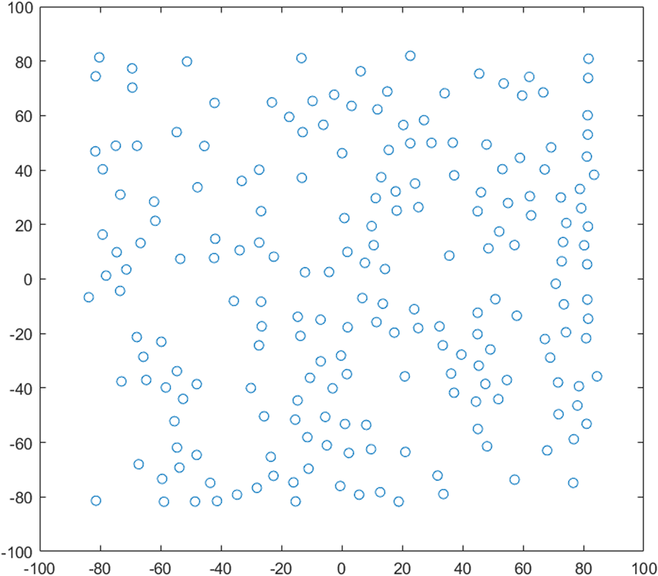
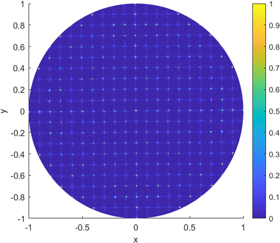
Taking into account the need for larger-sized elements, we establish a minimum distance of 8λ between adjacent elements. Following optimization, the array consists of 202 elements. Here, the coordinate values are expressed in terms of multiples of the wavelength. In Fig. 2, the center of each blue circle denotes the exact position of an element, and the element-to-element distance is measured from center to center.
Distribution of the 2D sparse array.

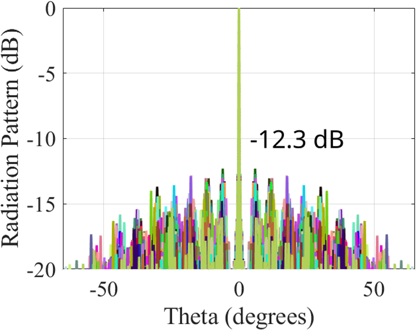
Figure 3 displays the radiation pattern of the antenna array across all 180 (from 0° to 180°with 1° as increment) ϕ-planes. Notably, no grating lobes are observed in this radiation pattern. The PSLL in all 180 ϕ-planes remains below −12.3 dB. These outcomes affirm that the pseudorandom distribution effectively suppresses both grating lobes and side lobes.
Radiation pattern of the sparse array with optimal configuration in 180 planes.

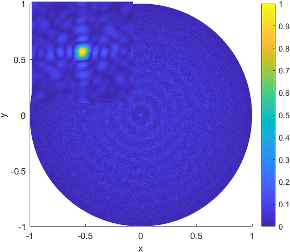
Figure 4 illustrates the 2D radiation pattern. The HPBW of the main lobe measures 0.3°. Given the small HPBW, the main lobe segment is enlarged and positioned in the left corner of the figure. This approach, utilizing 8λ inter-element distance, provides ample room for larger-sized elements. This stands in contrast to array designs employing optimization algorithms with 0.5λ or 0.6λ inter-element distances as reported in papers [Reference Chen, Dong, Jiao and Zhang19–Reference Enache, Deparateanu, Enache and Popescu21]. While these optimization algorithms yield lower PSLL due to their smaller inter-element distances, their performance tends to diminish as the inter-element distance increases. In contrast, in this instance, the inter-element distance can extend up to 8λ. This represents a clear advantage over previous optimization methods.
Radiation pattern of the sparse array (x = sin θ cos ϕ, y = sin θ sin ϕ. Note: The main beam is enlarged and put in the left corner of the figure).

As comparison, a periodic square array with an identical aperture and inter-element distance (8λ) is simulated. Theoretically, its main lobe should exhibit the same beam width as that of the pseudorandom array. The radiation pattern of the periodic array is depicted in Fig. 5. As observed, grating lobes emerge in various directions, leading to power dispersion and undesirable interference. When steering toward different directions, the range of steering is constrained by the presence of grating lobes. These drawbacks collectively render periodic arrays less favorable for practical applications.
Radiation pattern of the periodic array with the same aperture.

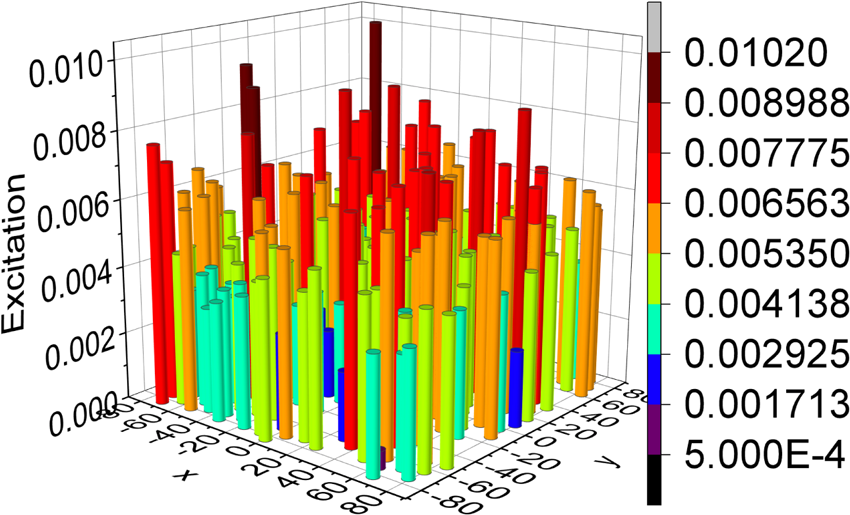
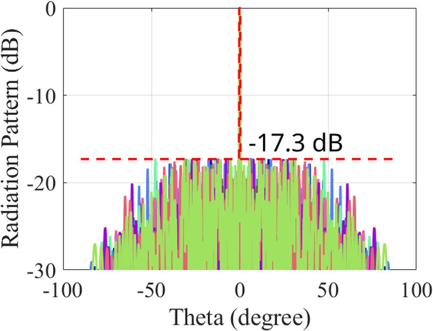
Figure 6 displays the excitation values for all the elements in the sparse array, while the positions of the elements in the array remain unchanged from the initial configuration. The primary contribution of the excitation optimization is the notable reduction in PSLL. As depicted in Fig. 7, a PSLL of −17.3 dB is attained, which is 5 dB lower than the pre-optimized PSLL shown in Fig. 3. This significant reduction in PSLL underscores the effectiveness of the optimization on the element excitations.
Excitation of each element in each position in this sparse array.

Radiation pattern of the sparse array after Convex optimization.

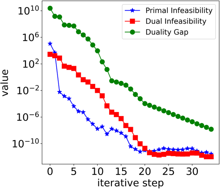
In Convex optimization, the SDPT3 solver employs a path-following algorithm to achieve convergence. This approach ensures a balanced maintenance of both primal and dual feasibility while effectively minimizing the duality gap. The convergence process is monitored using three primary indicators: primal infeasibility, dual infeasibility, and duality gap. The convergence criterion is defined as the maximum of these indicators being less than  $1.5 \times {10^{ - 8}}$ to ensure accuracy. The evolution of these indicators throughout the optimization process is illustrated in Fig. 8. This figure demonstrates that the convergence criteria are satisfied after 34 iterations, resulting in a small duality gap of
 $1.5 \times {10^{ - 8}}$. The relative primal and dual infeasibility are
 $2.9 \times {10^{ - 13}}$ and
 $1.1 \times {10^{ - 12}}$, respectively.
The values of primal infeasibility, dual infeasibility, and duality gap at each iterative step during the optimization process.

Beam steering performance
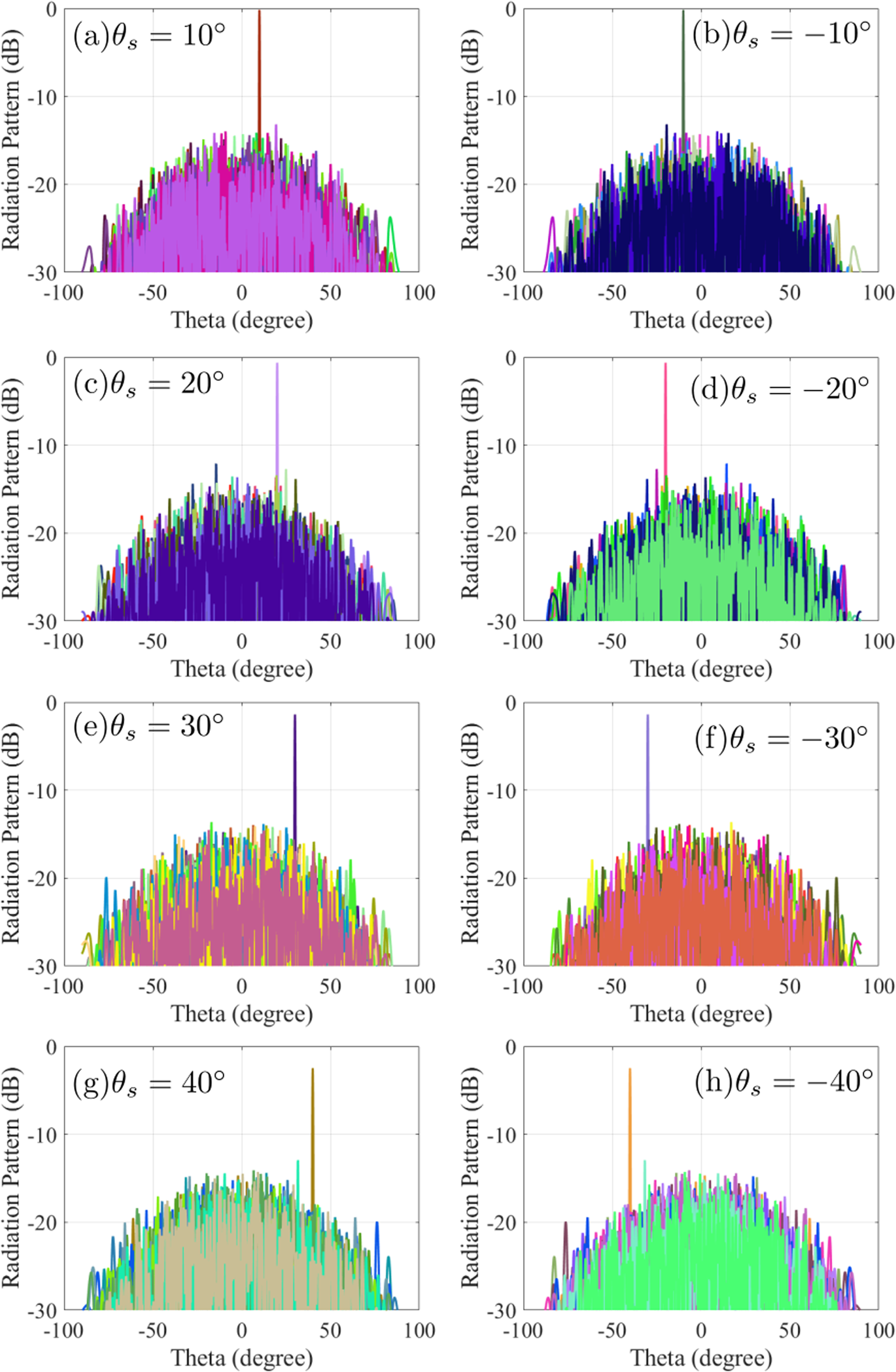
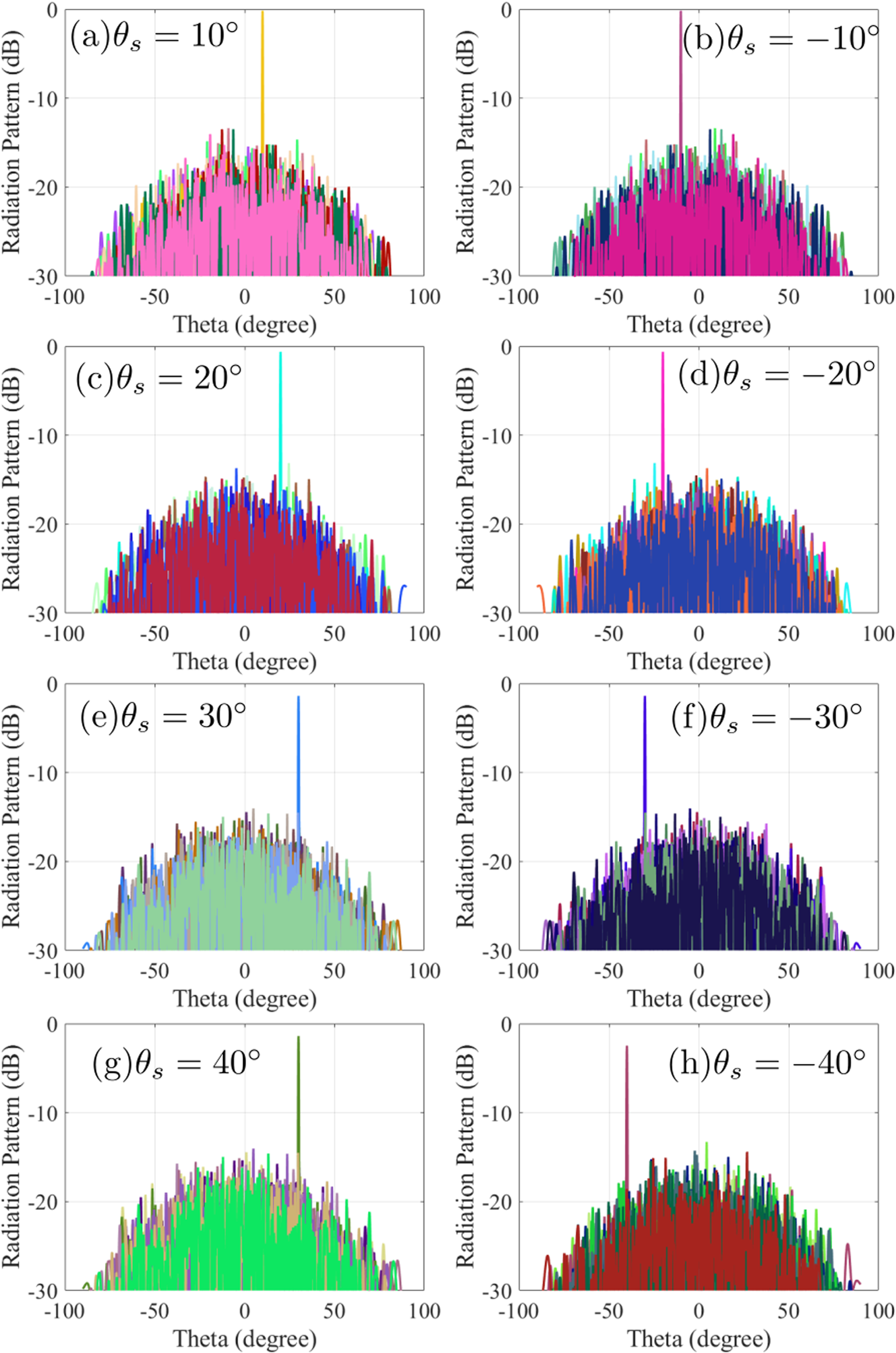
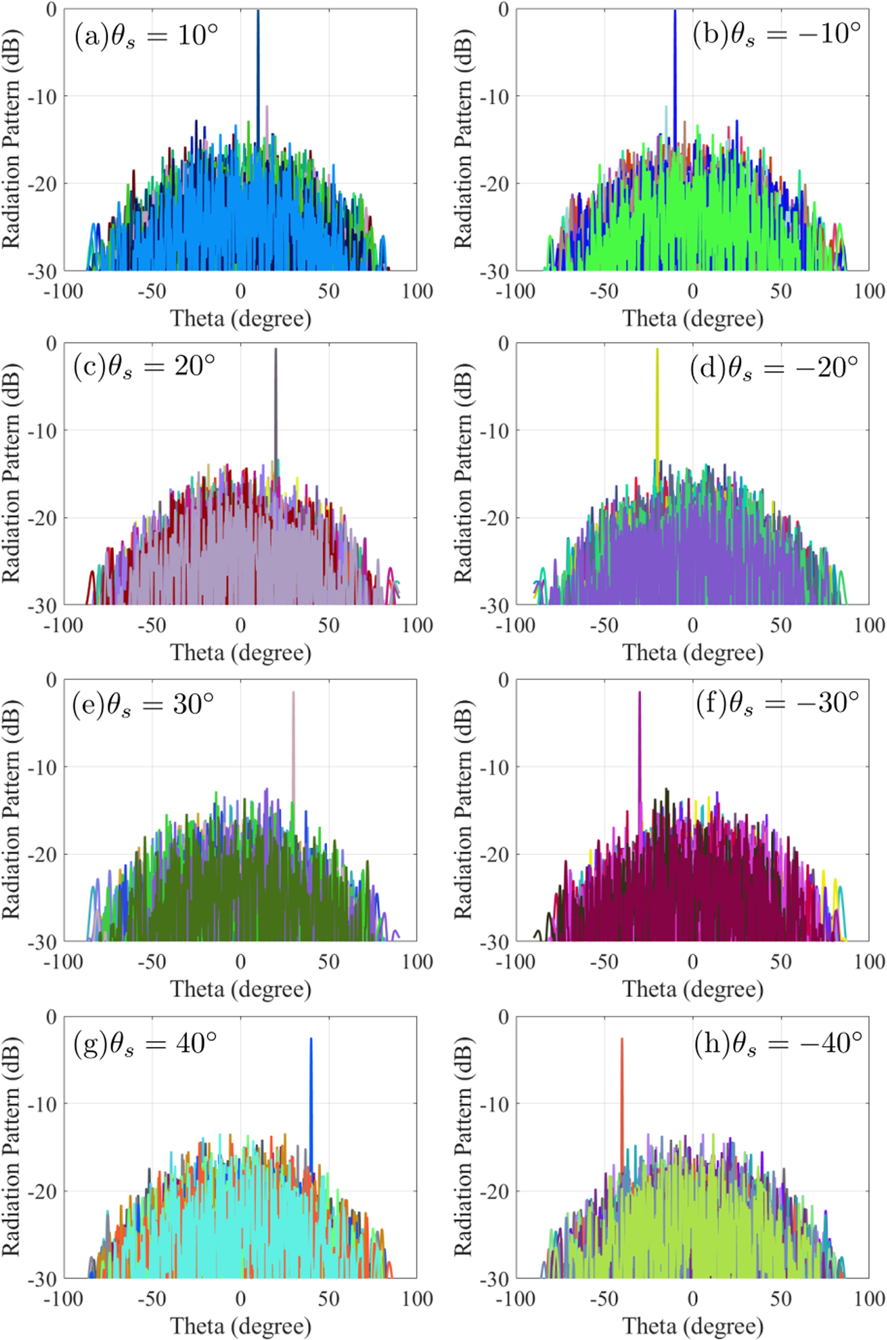
Beam steering is an important feature to investigate the effectiveness of array design [Reference Panduro and Del Rio29–Reference Reyna Maldonado and Panduro31]. Using the same array distribution and element excitations derived from the broadside pattern, we add different phases to steer the main lobe toward various directions within the range of (−40° to 40°). The radiation patterns of this sparse array when steering toward 10°, −10°, 20°, −20°, 30°, −30°, 40°, −40° in E plane, D plane, and H plane are shown in Figs. 9–11, respectively.
Radiation pattern in E plane when the steering angle is (a) 10°; (b) −10°; (c) 20°; (d) −20°; (e) 30°; (f) −30°; (g) 40°; (h) −40°.

Radiation pattern in D plane when the steering angle is (a) 10°; (b) −10°; (c) 20°; (d) −20°; (e) 30°; (f) −30°; (g) 40°; (h) −40°.

Radiation pattern in H plane when the steering angle is (a) 10°; (b) −10°; (c) 20°; (d)–20°; (e) 30°; (f) −30°; (g) 40°; (h) −40°.

The radiation patterns of the sparse array demonstrate excellent performance when the beam is steered toward all of these directions. The effective beam steering, characterized by low SLL within a wide field of view, is attributed to the entirely random design of the array configuration and the appropriate excitation optimization of the elements.
The radiation pattern results indicate the effectiveness of this hybrid design method. Grating lobes are avoided and low SLL are achieved while much fewer elements are used in the array plane. In addition, beam steering can be operated within 80° field-of-view range, which provides a solution for wide-range scanning applications. Compared with uniform array, the reduction of number of elements is an obvious advantage. The avoidance of grating lobes decreases power consumption and interference from other directions, increasing the efficiency and detection accuracy. Compared with some conventional sparse array design methods, such as PSO algorithm, GA, this design method can work on the arrays with larger inter-element distance (larger than half of wavelength). According to antenna theory, when the inter-element distance is or below half of wavelength, no grating lobe appears in radiation pattern. When the inter-element distance is beyond half of wavelength, the grating lobes appear in the radiation pattern. Thus, these methods are not able to achieve good radiation without the interference of grating lobes. However, our design can solve this problem. In addition to the avoidance of grating lobes, low level of PSLL can be achieved. Furthermore, the Delaunay Triangulation algorithm employed in this design can generate a sparse array with less calculation and time cost than some complex design methods [Reference Zhang, Bai, Zheng and Zhou25, Reference Mo, Tong, Wang, Wang, Luo and Li26].
The main contribution of the design method proposed in this paper is to provide possibility for sparse array applications where large-size elements are applied. The element number is significantly reduced. Therefore, the desired radiation pattern can be achieved with less cost and power consumption. The system complexity will also be reduced. Besides, larger distance between elements reduces mutual coupling among adjacent elements. For some antenna applications requiring high resolution and wide beam steering, this design can provide solution to solve these problems with less complexity and cost.
Conclusion
In conclusion, a hybrid design methodology based on Delaunay Triangulation and Convex optimization is proposed for planar sparse array design. In this design, Delaunay Triangulation algorithm is utilized to distribute the positions of elements and Convex algorithm is utilized to optimize the excitations of elements. Radiation pattern devoid of grating lobes and featuring low SLL can be achieved with a limited number of elements with a minimum inter-element distance of 8λ. This approach offers a distinct advantage in the form of large minimum inter-element distance. In comparison to periodic array, the reduction in the number of elements leads to lower power consumption and simplified manufacturing process. In addition, beam steering can be achieved with good performance within 80° field-of-view range.
Competing interests
The authors declare no conflicts of interest.

Pan Gao is PhD in Electrical Engineering department in Eindhoven University of Technology. She received Master degree from Chinese Academy of Sciences on optical engineering. She works on optical phased array, sparse array and laser.

Zhongquan Chen is currently a PhD candidate at the Eindhoven University of Technology, focusing on multiscale modeling of network dynamics. His Master’s work focused on statistical mechanics at the University of Saskatchewan in 2017.