1. Introduction
X-ray diffraction patterns from crystals of biological macromolecules contain decisive information for determining structures in atomic detail. Provided that the diffraction extends to Bragg spacings corresponding to ∼3 Å resolution, a typical pattern will have a number of observable, symmetry-independent reflections that exceeds the number of x, y, z parameters needed to specify atomic positions for the non-hydrogen atoms of the structure. At even lower resolution (∼5 Å), the number will still suffice to specify conformational torsion angles. Thus, in principle, diffraction data define the structure; however, the structural implication is through a large set of transcendental equations, each of which depends on all of the atomic parameters. This problem is intractable without having a model within the radius of convergence for refinement. There are no lenses for the hard x-rays needed for crystallography, as there are for visible light (optical lenses), electrons (magnetic lenses) or even soft x-rays (Fresnel zone plates); so the starting model cannot come from direct imaging. Fortunately, by the theory of diffraction, computational imaging by Fourier transformation is possible once phases as well as amplitudes are known for the diffracted waves. Hence, we face the phase problem – the need for ways to evaluate phases.
Crystallographic structure determination for biological macromolecules is influenced greatly by the small molecule tradition, which began with the solution of salt and mineral structures by trial-and-error approaches (Bragg, Reference Bragg1913b, Reference Bragg1914; Bragg & Bragg, Reference Bragg and Bragg1913) and later exploited images of interatomic-vector distributions (Patterson, Reference Patterson1934, Reference Patterson1935). The first approaches that really entailed phase evaluation, made relevant when Fourier syntheses were introduced (Bragg, Reference Bragg1929), were by isomorphous replacement from a centrosymmetric series of phthalocyanines (Robertson, Reference Robertson1936) and by the heavy-atom method as first used for the structure of platinum phthalocyanine (Robertson & Woodward, Reference Robertson and Woodward1940). In the heavy-atom method, phases were approximated by the contribution from the heavy atom and used to produce images of the lighter atoms. This approach was followed by the more general isomorphous replacement method for non-centrosymmetric structures (Bijvoet et al. Reference Bijvoet, Bokhoven and Schoone1948, Reference Bijvoet, Bokhoven and Schoone1949) as introduced in solving the structure of strychnine (Bokhoven et al. Reference Bokhoven, Schoone and Bijvoet1951). In this first application of isomorphous replacement, diffraction differences from substitution at a specific atomic site were exploited to obtain definitive phase information, albeit ambiguous in this case. Remarkably presaging the coming importance of selenium in biological crystallography, the substitution here was of selenate for sulfate. Finally, direct methods were derived for extracting phase information from relationships among crystallographic structure factors (Hauptman & Karle, Reference Hauptman and Karle1953; Karle & Hauptman, Reference Karle and Hauptman1950, Reference Karle and Hauptman1956), and computer implementations of direct methods came to dominate in small molecule crystallography.
Only isomorphous replacement was carried forward very directly from small molecule crystallography to macromolecular crystallography (Blow, Reference Blow1958; Green et al. Reference Green, Ingram and Perutz1954). As adapted to include multiple heavy-atom derivatives for resolving inherent ambiguities, the method of multiple isomorphous replacement (MIR) dominated in the first decades of protein crystallography. Anomalous scattering was realized to provide significant ancillary phase information (Blundell & Johnson, Reference Blundell and Johnson1976), which was used to augment MIR phasing into MIR with anomalous scattering (MIRAS) and to resolve ambiguities from single isomorphous replacement (SIR) as the SIRAS method (Blow & Rossmann, Reference Blow and Rossmann1961; Herriott et al. Reference Herriott, Sieker, Jensen and Lovenberg1970). Anomalous scattering information was also shown to suffice on its own for phase evaluation in the solution of the structure of crambin (Hendrickson & Teeter, Reference Hendrickson and Teeter1981), which we now see as the first application of method of single-wavelength anomalous diffraction (SAD). Ultimately, with the availability of tunable x-rays from synchrotron sources, practical implementation of the method of multiwavelength anomalous diffraction (MAD) was realized (Hendrickson, Reference Hendrickson1985; Kahn et al. Reference Kahn, Fourme, Bosshard, Chiadmi, Risler, Dideberg and Wery1985). Apart from isomorphous replacement, the small molecule methods are too weak to be effective for most macromolecular problems; however, the small molecule tradition influenced biological crystallography in many other ways. Patterson methods and direct methods are crucial for solving the substructures of phasing elements needed in MIR/SIR and MAD/SAD applications. Most importantly, the method of molecular replacement of knowns into unknowns (Lattman et al. Reference Lattman, Nockolds, Kretsinger and Love1971; Rossmann, Reference Rossmann1972), which now dominates in macromolecular crystallography, is in essence a phase borrowing closely related to that of the heavy-atom method. The crucial innovation here was the rotation function by Rossmann & Blow (Reference Rossmann and Blow1962).
Anomalous diffraction follows from the foundations of crystallography and the early development of protein crystallography, but it also has important roots in spectroscopy and, of course, an essential connection to synchrotron radiation. Synchrotron radiation, which was brought to the attention of biological crystallographers by Rosenbaum et al. (Reference Rosenbaum, Holmes and Witz1971), provides a bright continuum of x-rays; and fine tuning to the sharp resonant transitions responsible for anomalous scattering is critical for MAD phasing experiments and for optimized SAD phasing experiments. Such tuning was brought into practice for x-ray absorption spectroscopy (Kincaid et al. Reference Kincaid, Eisenberger, Hodgson and Doniach1975), and then adapted for anomalous x-ray diffraction experiments (Phillips et al. Reference Phillips, Templeton, Templeton and Hodgson1978).
The development and characteristics of MAD and SAD phasing have been described in several previous reviews (Blow, Reference Blow2003; Fourme & Hendrickson, Reference Fourme, Hendrickson and Hasnain1990; Hendrickson, Reference Hendrickson1991, Reference Hendrickson1999; Hendrickson & Ogata, Reference Hendrickson and Ogata1997; Ogata & Hendrickson, Reference Ogata and Hendrickson1995; Smith & Hendrickson, Reference Smith, Hendrickson, Rossmann and Arnold2001; Walsh et al. Reference Walsh, Evans, Sanishvili, Dementieva and Joachimiak1999). It took some time for this methodology to mature, however. Meanwhile, in the past decade and after most of these reviews, MAD and SAD have overtaken MIR and SIR and they now dominate dramatically as methods for the de novo crystal structures of biological macromolecules. In this review, I describe the overall course of development and document the impact of anomalous diffraction methods.
2. Physical basis for anomalous scattering
The interaction of x-rays with matter results in diverse physical phenomena including absorption, fluorescence, refraction and scattering (Als-Nielsen & McMorrow, Reference Als-Nielsen and McMorrow2011). These physical properties can be applied to problems in chemistry, biology and medicine including radiographic diagnosis and crystallographic structure determination. Our concern here is with the latter, which is based on elastic scattering whereby the incident x-ray energy (and hence wavelength) remains unchanged. X-rays are scattered from electrons, and the classical description of elastic scattering worked out by J. J. Thomson (Reference Thomson1906) for a free electron applies to good approximation for electrons in atoms as well. An incident electromagnetic wave induces sympathetic vibrations in the electron and the accelerated electron emits radiation in accord with Maxwell's equations. When integrated over the probability density for all electrons in an atom, as specified by the quantum-mechanical wave function, a total atomic scattering profile can be defined relative to the theoretical scattering from a free electron. This is the ‘normal’ atomic scattering factor, f°, which decreases with scattering angle as a function of S = |S| = 2 sin(θ)/λ, where S = h a* + k b* + l c* is the scattering vector for reflection h(h,k,l) from a crystal with reciprocal cell dimensions a*,b*,c*, θ is the Bragg scattering angle, and λ is the x-ray wavelength.
In reality, electrons are not passively free to respond to incident radiation; they are tied up into electronic orbitals at characteristic frequencies. As the x-ray oscillatory frequency approaches an atomic orbital frequency, the induced electron vibrations can resonate with the natural oscillations of the bound electrons, or more precisely with transitions from bound states to other accessible orbitals. This perturbs the atomic scattering (Als-Nielsen & McMorrow, Reference Als-Nielsen and McMorrow2011; James, Reference James1948). Such interactions also lead to photoelectric absorption whenever the x-ray energy exceeds the orbital binding energy, the absorption edge. This generates an ionized atom and a photoelectron; and such photoelectrons may recombine with the resulting ions to produce fluorescent x-rays with an energy characteristic of the particular electronic transition. The scattering perturbations due to orbital interactions add to the ‘normal’ Thomson scattering with increments, f Δ, that have both amplitude and phase shift components, |f Δ| and δ, and corresponding real and imaginary components, respectively f′ and f″. Thus, the true atomic scattering factor, f, is complex:
 $$f = f\hskip0pt\deg + f^{\rm \Delta} = f\hskip0pt\deg + \left| {\,f^{\rm \Delta}} \right|{\rm e}^{i\delta} = f\hskip0pt\deg + f' + {\rm i}f''.$$
The f Δ scattering perturbations are known as ‘anomalous’ scattering even though all electrons of interest are in electronic orbitals and truly are the norm. Physically, anomalous scattering is intimately connected to resonance and to absorption, and it is dispersive since the effect depends strongly on x-ray energy (E). Since anomalous scattering derives from core electrons, it is essentially independent of scattering angle; however, unlike normal scattering, it is a function of wavelength. Thus, f Δ = f (λ) ≠ f (S) whereas f° = f (S) ≠ f (λ).
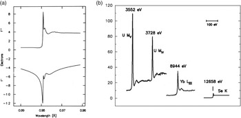
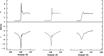
The spectra f′(λ) and f″(λ) can be evaluated for isolated atoms from quantum mechanical calculations (Cromer & Liberman, Reference Cromer and Liberman1970), but these do not apply for many resonant transitions which are from core atomic orbitals to unoccupied molecular orbitals. Fortunately, however, these factors can be evaluated experimentally from the connection between scattering, absorption and fluorescence. By Fresnel diffraction theory, the f° scattered wave is π/2 out of phase with the incident wave (James, Reference James1948), and f″ is out by another π/2; therefore, in the forward direction, the f″ component interferes destructively with the incident beam. This is the physical basis for absorption; f″(E) = K μ(E)·E, where K is a function only of physical constants and μ is the atomic absorption coefficient. The direct proportionality of fluorescence to absorption then makes the f″(λ) spectrum accessible [f″(λ) and f″(E) are equivalent since E = hc/λ; E(keV) = 12.3984/λ(Å)], and f′(λ) follows by Kramers–Kronig transformation (Hendrickson et al. Reference Hendrickson, Smith, Phizackerley and Merritt1988; Lye et al. Reference Lye, Phillips, Kaplan, Doniach and Hodgson1980). The full range of x-rays for diffraction experiments (∼3.5–35 keV or 0.35–3.5 Å) includes K and/or L absorption edges for all elements of Z ⩾ 20 (Ca and upwards) (Hendrickson & Ogata, Reference Hendrickson and Ogata1997). The light atoms of macromolecules (H, C, N and O) have negligible anomalous scattering in this range, but the f″ values for S and P are sufficiently substantial to be useful. Resonant enhancements can be pronounced even at K-edges as in selenoethers (Fig. 1 a), and they can be dramatic at the M-edges of actinides and at the LIII-edges of lanthanides (Fig. 1 b).
Anomalous scattering factor profiles. (a) Se K-edge anomalous scattering factors. These data derive from an x-ray absorption spectrum of selenomethionyl thioredoxin (Hendrickson et al. Reference Hendrickson, Horton and LeMaster1990). (b) Imaginary components of anomalous scattering at different absorption edges. The U MIV and U MV edges are from uranyl nitrate (Liu et al. Reference Liu, Ogata and Hendrickson2001), the Yb LIII edge is from a ytterbium-derivatized crystal of N-cadherin (Shapiro et al. Reference Shapiro, Fannon, Kwong, Thompson, Lehmann, Grübel, Legrand, Als-Nielsen, Colman and Hendrickson1995), and the Se K edge is from a crystal of selenomethionyl human choriogonadotropin (Wu et al. Reference Wu, Lustbader, Liu, Canfield and Hendrickson1994). Reproduced from Hendrickson et al. (Reference Hendrickson, Horton and LeMaster1990) for (a) with permission from the EMBO Journal, © 1990 EMBO, and from Liu et al. (Reference Liu, Ogata and Hendrickson2001) for (b) with permission from the Proceedings of the National Academy of Sciences of the United States of America, © 2001 National Academy of Sciences.

3. Historical background
3.1 Discovery and description of anomalous scattering
The first recorded evidence for anomalous x-ray scattering was from Mark & Szilard (Reference Mark and Szilard1925) who showed that diffraction from RbBr crystals differed selectively depending on the wavelength of irradiating x-rays. The RbBr structure is like that of rock salt (NaCl) and, as Rb+ and Br− ions are isoelectronic and have equivalent f° scattering factors, only even orders of [111] diffraction were observed with x-rays from Fe, Co, Cu or Zn anodes, which have x-ray energies (7.1–9.7 keV) remote from the absorption edges of Rb or Br. With Sr Kα radiation, however, both the (1,1,1) and (3,3,3) diffraction lines were also observed; here the stimulating x-rays (14.1 keV) fall between the K absorption edges of Br (13.5 keV) and Rb (15.2 keV) whereby the anomalous scattering appreciably and differentially affects the net Br and Rb scattering.
An especially celebrated demonstration of anomalous scattering came from an elegant experiment by Coster et al. (Reference Coster, Knol and Prins1930) showing the breakdown of Friedel's law, I(h,k,l)≠I(−h,−k,−l), in diffraction from zincblende (ZnS). Using a gold anode to produce x-rays, these investigators found dramatic differences in the ratio of intensities in Au Lα 1 to Au Lα 2 lines seen for (1,1,1) as compared with (−1,−1,−1) reflections and also for (3,3,3) versus (−3,−3,−3) reflections. The Zn K absorption edge (9.66 keV) falls between the two Au L lines, with Au Lα 2 (9.63 keV) being below the edge and Au Lα 1 (9.71 keV) being above the edge; thus, since f″ (Zn) is then large at Lα 1, the differences in intensities between Friedel mates are also large. According to Ramaseshan (Reference Ramaseshan1993), this influential study was inspired by similar zincblende experiments, albeit more preliminary, based on tungsten Lβ lines (Nishikawa & Matukawa, Reference Nishikawa and Matukawa1928).
Quantification of the dispersion of x-rays came from accurate measurements of atomic scattering factors as a function of x-ray wavelength in the neighborhood of an absorption edge. Observations by Wyckoff (Reference Wyckoff1930) on nickel oxide with MoKα, CuKα and NiKα radiations were especially notable in this context, showing dispersion for Ni scattering factors but not for O scattering factors.
The observation of anomalous dispersion of x-rays prompted theoretical investigations of the phenomena (Kallman & Mark, Reference Kallman and Mark1927); and, to an extent, theoretical studies (Prins, Reference Prins1928) spurred the experiments. The quantum dispersion theory (Kramers & Heisenberg, Reference Kramers and Heisenberg1925) was extended to analysis of the refraction, absorption and dispersion of x-rays (Kronig, Reference de Kronig1926; Kronig & Kramers, Reference de Kronig and Kramers1928). The most complete quantum elaboration came in the theory of Hönl (Reference Hönl1933), which used atomic wave functions to obtain oscillator strengths and from them the photoelectric absorption cross-sections were needed to calculate scattering factor corrections.
3.2 Antecedents of MAD and SAD phasing for macromolecules
Phenomena associated with anomalous scattering fascinated physicists as being manifestations of the quantum nature of atoms and for developing x-ray diffraction theory. Even though phase shifts were understood to accompany the resonances responsible for the anomalies (Coster et al. Reference Coster, Knol and Prins1930), there seems to have been no motivation for physicists at the time to exploit these effects for structure determination. Missing such opportunity is understandable since phase evaluation came only later to be employed in structure determination (Robertson, Reference Robertson1936) once Fourier approaches had been introduced (Bragg, Reference Bragg1929; see discussion by Hendrickson, Reference Hendrickson2013); however, it is surprising that it took so long for this inspiration to strike (Bijvoet, Reference Bijvoet1949). The lag is all the more remarkable since Bijvoet himself had been instrumental in prompting Ewald to reconsider his ‘proof’ of Friedel's Law (Ewald & Hermann, Reference Ewald and Hermann1927).
Reduction to practice for the idea of phase evaluation from anomalous scattering was slow to come, although Bijvoet did develop the method of isomorphous replacement in the same time frame (Bijvoet et al. Reference Bijvoet, Bokhoven and Schoone1948, Reference Bijvoet, Bokhoven and Schoone1949). Anomalous differences tend to be smaller than isomorphous differences and, to be general, there are issues of phase ambiguity; however, the deviations from Friedel symmetry in diffraction from rubidium tartrate did suffice to determine absolute configuration for the first time (Bijvoet et al. Reference Bijvoet, Peerdeman and van Bommel1951). Bijvoet later reviewed these influential and pioneering uses of anomalous diffraction (Bijvoet, Reference Bijvoet1954).
The phase problem was a preoccupying concern in the intellectual ferment of 1950s crystallography, and anomalous scattering stimulated several new formulations for phase determination (Herzenberg & Lau, Reference Herzenberg and Lau1967; Karle, Reference Karle1967; Mitchell, Reference Mitchell1957; Okaya & Pepinsky, Reference Okaya and Pepinsky1956; Okaya et al. Reference Okaya, Saito and Pepinsky1955; Ramachandran & Raman, Reference Ramachandran and Raman1956; Raman, Reference Raman1959; Ramaseshan & Venkatesan, Reference Ramaseshan and Venkatesan1957; Singh & Ramaseshan, Reference Singh and Ramaseshan1968). Practical implementations also followed; however, at the time, these were limited to the characteristic wavelengths available from the anode coatings of Roentgen-like x-ray tubes. Nevertheless, pioneering multi-wavelength tests were performed to resolve the phase ambiguity presented by non-centrosymmetric structures. Notably, Ramaseshan et al. (Reference Ramaseshan, Venkatesan and Mani1957) bracketed the Mn K absorption edge with FeKα and CoKα radiations and solved the crystal structure of KMnO4; and Hoppe & Jakubowski (Reference Hoppe, Jakubowski, Ramaseshan and Abrahams1971) carried out two-wavelength tests on a fly hemoglobin using CoKα and NiKα x-ray, which similarly lie on either side of the Fe K edge of heme.
Ramaseshan (Reference Ramaseshan1993) has given an engaging history of early work leading to multiwavelength phasing for biological molecules.
3.3 Synchrotron radiation
The bremsstrahlung emission from x-ray tubes does afford access to a continuous x-ray spectrum, indeed, this continuum proved to be the origin of the first x-ray patterns (Bragg, Reference Bragg1913a; Friedrich et al. Reference Friedrich, Knipping and Laue1912); however, the far more intense characteristic x-ray emissions from electron-bombarded anodes became the mainstay for structure determinations. By contrast, the continuum of synchrotron radiation is exceptionally bright across a wide spectrum determined by the critical energy of the source. Soon after the realization that synchrotron radiation could be useful for biological diffraction (Rosenbaum et al. Reference Rosenbaum, Holmes and Witz1971), experiments also followed to extract structural information about metal coordination in metalloproteins by x-ray absorption spectroscopy (Cramer & Hodgson, Reference Cramer and Hodgson1979; Kincaid et al. Reference Kincaid, Eisenberger, Hodgson and Doniach1975) and to extract anomalous scattering factors from the finely tuned near-edge variations in x-ray absorption (Phillips et al. Reference Phillips, Templeton, Templeton and Hodgson1978; Templeton et al. Reference Templeton, Templeton, Phillips and Hodgson1980, Reference Templeton, Templeton, Phizackerley and Hodgson1982).
That synchrotron measurements of anomalous diffraction from appropriately derivatized crystals could be used effectively in structure determination was appreciated immediately (Lye et al. Reference Lye, Phillips, Kaplan, Doniach and Hodgson1980; Phillips & Hodgson, Reference Phillips and Hodgson1980; Templeton et al. Reference Templeton, Templeton, Phillips and Hodgson1980) and a first application came with the test structure of Tb3+-derivatized parvalbumin (Kahn et al. Reference Kahn, Fourme, Bosshard, Chiadmi, Risler, Dideberg and Wery1985). We had also learned from our experience in determining the structure of crambin from the weak anomalous scattering of CuKα x-rays by its intrinsic sulfur atoms that native anomalous scattering can suffice (Hendrickson & Teeter, Reference Hendrickson and Teeter1981), and our experience in x-ray absorption spectroscopy of hemerythrin (Hendrickson et al. Reference Hendrickson, Co, Smith, Hodgson and Klippenstein1982) indicated that iron proteins might be excellent candidates. Thus, we successfully used lamprey hemoglobin as a first test subject (Hendrickson, Reference Hendrickson1985; Hendrickson et al. Reference Hendrickson, Smith, Phizackerley and Merritt1988).
We named the new method multiwavelength anomalous diffraction, giving the acronym MAD for its parallel with MIR, then the dominant phasing method. In both cases, information from multiple sets of measurements (at differing wavelengths for MAD and from different isomorphs for MIR) is used to break the trigonometric phase ambiguity that occurs in general when only a single set of measurements is used. The first use of the term MAD, to the best of my knowledge, was in a main lecture at the IUCr Congress in Hamburg in 1984 (Hendrickson, Reference Hendrickson1984), and this term was then adopted in the first publications describing structure determinations by the method (Harada et al. Reference Harada, Yasui, Murakawa, Kasai and Satow1986; Hendrickson, Reference Hendrickson1985; Kahn et al. Reference Kahn, Fourme, Bosshard, Chiadmi, Risler, Dideberg and Wery1985).
4. Theoretical foundation for phase evaluation from anomalous diffraction
Our analysis for deriving phase information from measurements of anomalous diffraction is based on the fundamental additivity of scattered x-ray waves, whereby one here exploits the interference between scattering from anomalous centers and that from all other atoms. We distinguish the relatively few anomalous scatterers (A), for which the anomalous component (f Δ) is substantial, from the many ‘normal’ scatterers (N), for which f Δ is considered negligible, and the sum of the two gives the total from all atoms (T) in the structure. Since deviations from normal diffraction arise only from the anomalous scatterers, it is possible to isolate the anomalous contribution to the total diffraction and from it to deduce positions for the anomalous scatterers. With these scattering components in hand, both in phase and amplitude, then by the principles of interference it becomes possible to deduce the otherwise unknown phases for diffracted waves from the total structure. We perform this analysis in a unified treatment of all observations, using an algebraic approach developed in principle by Karle (Reference Karle1980) and reduced to practice after reformulation (Hendrickson, Reference Hendrickson1985, Reference Hendrickson1991; Hendrickson et al. Reference Hendrickson, Smith, Phizackerley and Merritt1988).
Each kind of anomalous scatterer (k), having distinctive scattering factors, contributes to the total diffraction as the sum of a wavelength-independent component due to its normal scattering (f°) and a wavelength-variant component due to its anomalous scattering (f Δ = f′ + i f″). Thereby,
 $$^\lambda F_{{\rm A}_{\rm k}} = \hskip0pt\deg F_{{\rm A}_{\rm k}} +\ ^\lambda \hskip-2pt{ F\hskip1 }\prime\hskip-4 _{{\rm A}_{\rm k}} + i\ ^\lambda F_{{\rm A}_{\rm k}} {\hskip-6pt ''} = \left[ {1 + \left( {\,f'/f\hskip0pt\deg} \right) + i \left( {\,f''/f\hskip0pt\deg} \right)} \right]\hskip0pt\deg F_{{\rm A}_{\rm k}}, $$
where
 $^\lambda F_{{\rm A}_{\rm k}} $
denotes the complete wavelength-dependent contribution of atoms Ak, which is composed from
 $\hskip0pt\deg F_{{\rm A}_{\rm k}} = {\rm f}(\; f\hskip0pt\deg_{\hskip-4pt k} )$
,
 $^\lambda{ F\hskip1 }\prime\hskip-4 _{{\rm A}_{\rm k}} \cent = {\rm f} \left( {\;{ f \hskip.5}\prime\hskip-4 _k} \right)$
and
 $^\lambda F_{{\rm A}_{\rm k}} \hskip-6pt{\Prime} = {\rm f} (\; f_k {\hskip-1.5pt\Prime } )$
. Furthermore, since the normal scattering component of each anomalous scatterer contributes along with all normal scatterers to the total scattering,
 $\hskip0pt\deg F_{\rm T}  = \hskip0pt\deg F_{\rm N}  + \sum _k \hskip0pt\deg F_{{\rm A} _{_{\rm k}}} $
. Thus, diffraction measurements associated with a specified Bragg reflection h(h,k,l) made at a particular wavelength λ are given by
 $${}^\lambda F({\bf h}) =\hskip0pt\deg F_{\rm T} ({\bf h}) + \sum\nolimits_k {[(\,f'/f^\hskip0pt\deg )} + i(\,f'' /f^\hskip0pt\deg )]{\hskip0pt\deg} F_{{\rm A} _{_{\rm k}}} ({\bf h}), $$
where
λF(h) is the wavelength-dependent total structure factor for reflection h, and °F
T(h) = |°F
T| exp(i°ϕ
T) and
 $\hskip0pt\deg F_{{\rm A} _{\rm k}} ({\bf h}) = \left| {\hskip0pt\deg F_{{\rm A} _{\rm k}}} \right|{\rm exp}\,(i\hskip0pt\deg \phi _{{\rm A} _{\rm k}} )$
are corresponding wavelength-invariant components.
Equation (3) is general as the kinds of anomalous scatterers can be arbitrarily broad; however, in most cases the number of effective kinds is limited, often just to one. Usually, the light atoms (H, C, N and O) of macromolecules are treated as ‘normal’ scatterers having scattering factors f = f° even though an anomalous scattering component (f Δ = f′ + i f″) is never strictly absent. Moreover, for measurements made at higher energy (>7 keV) the components from S and P atoms can be considered negligible relative to those at resonance from heavier elements such as Fe, Se, Hg or Yb. Even when multiple kinds of anomalous scatterers are present, one kind usually dominates; and to a useful initial approximation the equation can be so limited.
The observable quantity in a diffraction experiment is the diffracted intensity I(h) = K |F(h)|2; and |F|2 expands by Eq. (2) for the case of a single kind of anomalous scatterer to
 $$\eqalign{\left| {^\lambda F( \pm {\bf h})} \right|^2 = \left| {\hskip0pt\deg F_{\rm T} ({\bf h})} \right|^2\, +\, a(\lambda )\left| {\hskip0pt\deg F_{\rm A} ({\bf h})} \right|^2 \, +\,& b (\lambda )\left| {\hskip0pt\deg F_{\rm T} ({\bf h})} \right|\left| {\hskip0pt\deg F_{\rm A} ({\bf h})} \right|{\rm cos}\left( {\hskip0pt\deg \phi _{\rm T} - \hskip0pt\deg \phi _{\rm A}} \right) \cr &\hskip-13 \pm\hskip-1pt c(\lambda )\left| {\hskip0pt\deg F_{\rm T} ({\bf h})} \right|\left| {\hskip0pt\deg F_{\rm A} ({\bf h})} \right|{\rm sin}\left( {\hskip0pt\deg \phi _{\rm T} - \hskip0pt\deg \phi _{\rm A}} \right),} $$
where
 $$a(\lambda ) = \left( {{{\left| {\,f^\Delta} \right|} / {\,f\hskip0pt\deg}}} \right)^2 ;\quad b(\lambda ) = 2\left( {{{\,f\hskip1pt '} / {\,f\hskip0pt\deg}}} \right);\quad {\rm and}\quad c(\lambda ) = 2\left( {{{\,f\hskip1pt ''} / {\,f\hskip0pt\deg}}} \right).$$
Only the wavelength-invariant normal scattering factors f° contribute to °F T and °F A, amplitudes and phases, including all atoms for °F T but just one kind of anomalous scatterer for °F A. All wavelength dependence is separated into factors a(λ), b(λ) and c(λ) defined by the spectral dependence of anomalous scattering.
Equations (4) encode an elegant and unified theory that can afford a definitive solution of the phase problem, which is implemented in the MADSYS system of programs (Hendrickson, Reference Hendrickson1985, Reference Hendrickson1991). Normal scattering factors f° are known from quantum mechanical calculation, and the anomalous scattering factors f′ and f″ can be deduced from a combination of x-ray absorption spectra and theory (Hendrickson et al. Reference Hendrickson, Smith, Phizackerley and Merritt1988), whereby wavelength-dependent factors a(λ), b(λ) and c(λ) are determined. Alternatively, these factors can be refined from rough approximations (Fanchon & Hendrickson, Reference Fanchon and Hendrickson1990; Templeton & Templeton, Reference Templeton and Templeton1982; Weis et al. Reference Weis, Kahn, Fourme, Drickamer and Hendrickson1991). The set of observations, {| λF(h)|2}, of Bijvoet mates at various wavelengths constitute, for each reflection h, a set of simultaneous equations (Eq. 4) that can be solved subject to trigonometric identities to yield the wavelength-invariant structure-factor quantities: |°F T(h)|, |°F A(h)| and Δϕ = (°ϕ T−°ϕ A). The set of |°F A(h)| from all reflections can then be used to determine and refine the atomic substructure of anomalous scattering centers, {r A }, by relatively straightforward Patterson or direct methods. Phases calculated from this substructure solve the phase problem, °ϕ T = Δϕ + °ϕ A calc, provided that the correct enantiomorph, {±r A }, has been determined. In practice, the solution is represented as a phase probability distribution (Pähler et al. Reference Pähler, Smith and Hendrickson1990).
In addition to providing a possible algebraic solution, Eq. (4) also provides useful, approximation-free descriptions of the deviations from normal diffraction due to anomalous scattering. It is evident that | λF(h)| is independent of wavelength in the absence of anomalous scattering (f Δ = 0); and then structure factor values are independent of wavelength and identical for Friedel mates | λF(±h)| or their symmetry equivalents (called Bijvoet mates). Deviations of | λF(±h)| from |°F T(h)| are often small and best captured in salient differences. The Bijvoet difference is directly proportional to f″ and to sin(Δϕ):
 $$\left| {{}^\lambda F({\bf h})} \right|^2 - \left| {{}^\lambda F( - {\bf h})} \right|^2 = 2\,c(\lambda )\left| {\hskip0pt\deg F_{\rm T} ({\bf h})} \right|\left| {\hskip0pt\deg F_{\rm A} ({\bf h})} \right|\,{\rm sin}\left( {\hskip0pt\deg \phi _{\rm T} - \hskip0pt\deg \phi _{\rm A}} \right).$$
If anomalous scattering effects are relatively small, as commonly happens, then |°F T(h)|≈(| λF(h)| + | λF(−h)|)/2 and one obtains the Bijvoet-difference equation used for the SAD phasing analysis of the crambin structure (Hendrickson & Teeter, Reference Hendrickson and Teeter1981):
 $${}^\lambda {\rm \Delta} F_ {\pm {\bf h}} \approx \left| {{}^\lambda F({\bf h})} \right| - \left| {{}^\lambda F( - {\bf h})} \right| = c(\lambda )\left| {\hskip0pt\deg F_{\rm A} ({\bf h})} \right|\,{\rm sin}\left( {\hskip0pt\deg \phi _{\rm T} - \hskip0pt\deg \phi _{\rm A}} \right){\rm,} $$
from which there are two possible values of °ϕ T when the atomic substructure of anomalous scattering centers, {r A }, is known. Absent data from multiple wavelengths, other added information such as from density-modification methods is needed for resolution of this phase ambiguity.
Dispersive differences between two wavelengths, λ i and λ j, are more complicated, but they can be described as the differences between the respective intensity means, 〈| λF(h)|2〉 = (| λF(h)|2 + | λF(−h)|2)/2:
 $$\eqalign{\left\langle {\left| {{}^{\lambda _{\rm i}}F({\bf h})} \right|^2} \right\rangle - \left\langle {\left| {{}^{\lambda _{\rm j}}F({\bf h})} \right|^2} \right\rangle =&\ \left[ {a(\lambda _{\rm i} ) - a(\lambda _{\rm j} )} \right]\left| {\hskip0pt\deg F_{\rm A} ({\bf h})} \right|^2 \cr &\hskip-9 + \left[ {b(\lambda _{\rm i} ) - b(\lambda _{\rm j} )} \right]\left| {\hskip0pt\deg F_{\rm T} ({\bf h})} \right|\left| {\hskip0pt\deg F_{\rm A} ({\bf h})} \right|\,{\rm cos}\left( {\hskip0pt\deg \phi _{\rm T} - \hskip0pt\deg \phi _{\rm A}} \right).} $$
Unless |°F A(h)| is on the order of |°F T(h)|, which only happens for very strong anomalous scattering, the second term dominates and |°F T(h)|≈(〈| λ i F(h)|〉 + 〈| λ j F(h)|〉)/2. In such typical cases, the dispersive difference is thereby:
 $$\Delta F_{\Delta \lambda} \approx \left\langle {\left| {^{\lambda _{\rm i}} F({\bf h})} \right|} \right\rangle - \left\langle {\left| {^{\lambda _{\rm j}} F({\bf h})} \right|} \right\rangle = {{1\over 2}} \left[ {b(\lambda _{\rm i} ) - b(\lambda _{\rm j} )} \right]\left| {\hskip0pt\deg F_{\rm A} ({\bf h})} \right|\,{\rm cos}\left( {\hskip0pt\deg \phi _{\rm T} - \hskip0pt\deg \phi _{\rm A}} \right),$$
whereas Bijvoet differences are proportional to f″ (λ i) and sin(Δϕ), dispersive differences are proportional to |f′(λ i)−f′(λ j)| and to cos(Δϕ), which nicely demonstrates the orthogonality of information needed for definitive phase evaluation.
It is helpful to have estimates of the strength of signal expected in a MAD or SAD experiment, and the approximations of Eqs. (6) and (8) for Bijvoet and dispersive differences make such estimates possible. We do this by obtaining the ratios of relevant averaged anomalous differences relative to the averaged total diffraction (Hendrickson, Reference Hendrickson1991), where averages are taken as root-mean-squared (rms) values over all data with extrapolation to zero scattering angle. Since the expected value for lim(h→0)〈| λF(±h)|2〉≈〈|°F T(h)|2〉 = ∑f°(0)2≈N T Z eff 2 where N T is the number of non-hydrogen atoms and Z eff is the effective atomic number for an average non-hydrogen atom. Thus, rms (F T)≈√N T Z eff. Z eff = 6.7 for proteins. A similar averaging pertains to differences from the anomalous substructure, but here the averaging must include the trigonometric factors, where 〈sin(θ)〉 = 〈cos(θ)〉 = ½. Taken all together, we obtain the ratios
 $${\rm Rms}\,\left( {^\lambda {\rm \Delta} F_ {\pm {\rm h}}} \right)/{\rm Rms}\,(F_{\rm T} ) \approx \left( {N_{\rm A} /2\,N_{\rm T}} \right)^{\raise.5ex\hbox{$\scriptstyle 1$}\kern-.1em/ \kern-.15em\lower.25ex\hbox{$\scriptstyle 2$}} \times \left( {2\,f''\left( \lambda \right)/Z_{{\rm eff}}} \right)$$
and
 $${\rm Rms}\,({\rm \Delta} F_{{\rm \Delta} \lambda} )/{\rm Rms}\,(F_{\rm T} ) \approx \left( {N_{\rm A} /2\,N_{\rm T}} \right)^{\raise.5ex\hbox{$\scriptstyle 1$}\kern-.1em/ \kern-.15em\lower.25ex\hbox{$\scriptstyle 2$}} \times \left( {\left| {\,f'(\lambda _{\rm i} ) - f'(\lambda _{\rm j} )} \right|/Z_{{\rm eff}}} \right).$$
MAD experiments can be thought of as in situ MIR experiments, carried out with physical instead of chemical replacements, and they can be analyzed accordingly (Phillips & Hodgson, Reference Phillips and Hodgson1980) or by earlier alternative methods (Okaya & Pepinsky, Reference Okaya and Pepinsky1956). The dispersive differences defined by Eq. (7) are like those in isomorphous replacement and the Bijvoet differences defined by Eq. (6) are like the anomalous differences added to give SIRAS and MIRAS.
5. Development of MAD
The antecedents of MAD analyses for macromolecules did include the remarkable two-wavelength test on Chrionomus hemoglobin by Hoppe & Jakubowski (Reference Hoppe, Jakubowski, Ramaseshan and Abrahams1971) and the single-wavelength structure of crambin (Hendrickson & Teeter, Reference Hendrickson and Teeter1981), both using characteristic Kα lines from metal anodes; however, the true beginnings of MAD came with developments from synchrotron radiation.
5.1 Beginnings of MAD phasing for macromolecules
The first published MAD analysis of a protein structure was that for a parvalbumin from the toadfish Opsanus tau. Kahn et al. (Reference Kahn, Fourme, Bosshard, Chiadmi, Risler, Dideberg and Wery1985) performed a three-wavelength experiment at LURE, taking advantage of the strong white-line resonance of Tb3+, which was substituted into Ca2+ sites. Measurements were made at the absorption maximum (λ = 1.649 Å), at the inflection point (Δλ = 0.0011 Å) and at a shorter wavelength (Δλ = − 0.0021 Å). These wavelengths corresponded to an energy of 7.5137 keV at the LIII-edge, an energy 5 eV beyond the edge at the absorption peak, and a slightly remote energy just 15 eV above the edge. Scattering factor values were first estimated from the scan of differences from a particularly strong Bijvoet pair and then refined against the complete data set. An electron-density map computed at 2.3 Å resolution compared favorably with the structure solved independently by molecular replacement.
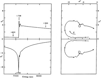
In the same timeframe, experiments were conducted at SSRL using lamprey hemoglobin as a test problem, and it was results from these experiments that were used to describe MAD phasing at the IUCr Congress in 1984 (Hendrickson, Reference Hendrickson1984). The lamprey hemoglobin analysis was first described at 5.5 Å resolution (Hendrickson, Reference Hendrickson1985) and then at 3.0 Å resolution (Hendrickson et al. Reference Hendrickson, Smith, Phizackerley and Merritt1988). This was a four-wavelength experiment that included the inflection (edge) and peak positions at the Fe K-edge as well as a remote low- and high-energy positions, respectively 245 and 1140 eV below and above the edge. Fluorescence measurements of x-ray absorption were scaled to fit theoretical f″ values outside the edge region (6.68–7.40 keV) and then used to derive f′ values by Kramers–Kronig transformation (Kronig & Kramers, Reference de Kronig and Kramers1928). The extended span of energies here was chosen, as illustrated in Fig. 2, to enhance the dispersive signals which depend on Δf′ = f′(λ i) − f′(λ j). Crystals were mounted in capillaries and maintained at ∼10°C, and diffraction data were measured with a multi-wire electronic area detector.
Experimental anomalous scattering factors for lamprey hemoglobin. (Left) Imaginary and real components, above and below respectively, of Fe scattering factors in type D2 lamprey hemoglobin, measured with E parallel b. Experimental fluorescence data were fitted into theoretical atomic scattering factor spectra, retaining experimental values in the near-edge region. Wavelengths of the diffraction measurements are indicated by arrows. (Right) Herzenberg–Lau scattering factor profiles (Herzenberg & Lau, Reference Herzenberg and Lau1967). Wavelengths of diffraction measurements are indicated by solid circles. Reproduced from Hendrickson et al. (Reference Hendrickson, Smith, Phizackerley and Merritt1988) with permission from Proteins, © 1988 Alan R. Liss, Inc.

Other early MAD experiments were also conducted at low resolution or on test systems (Harada et al. Reference Harada, Yasui, Murakawa, Kasai and Satow1986; Korzun, Reference Korzun1987), but the focus of attention soon moved to true applications. The first of these to be reported was that for cucumber basic blue protein by Guss et al. (Reference Guss, Merritt, Phizackerley, Hedman, Murata, Hodgson and Freeman1988), a structure that had eluded attempts by other methods. This study used the same experimental approach and instrumentation as that employed in the lamprey hemoglobin work, but in this case copper atoms produced the anomalous scattering. A four-wavelength experiment was conducted as for lamprey hemoglobin, here ranging from 949 eV below the edge to 1040 eV above the edge. The MAD data were measured to 2.5 Å spacings, but then used to compute electron-density maps at 3.0 Å resolution from which the structure was interpreted and subsequently refined at 1.8 Å resolution.
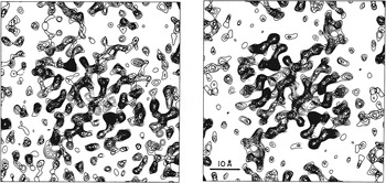
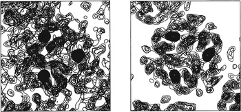
Our own first application to a novel structure was that to streptavidin, which we solved as a complex with selenobiotin (Hendrickson et al. Reference Hendrickson, Pähler, Smith, Satow, Merritt and Phizackerley1989). Experiments were conducted both at SSRL and at a diffractometer facility at Photon Factory beamline 14A. Whereas high-energy resolution at SSRL permitted a characterization of anisotropy in anomalous scattering from seleonbiotinyl streptavidin, resulting diffraction data measured there were of insufficient quality for an interpretable result. Despite poor energy resolution at PF 14A, a three-wavelength MAD experiment (inflection, peak and a remote point 1118 eV above the edge) gave a readily interpretable map that was further improved by averaging of non-crystallographic symmetry (Fig. 3). The excellence of this result based on a single Se atom from selenobiotin also inspired us to develop selenomethionyl proteins, which proved to provide great generality for MAD analyses (Hendrickson et al. Reference Hendrickson, Horton and LeMaster1990).
MAD-phased electron-density distributions for selenobiotinyl streptavidin. (Left) Map at 3.3 Å resolution based exclusively on MAD phasing (m = 0.78). (Right) Map at 3.3 Å resolution after twofold molecular averaging refinement of initial phases (m = 0.90). Reproduced from Hendrickson et al. (Reference Hendrickson, Pähler, Smith, Satow, Merritt and Phizackerley1989) with permission from the Proceedings of the National Academy of Sciences of the United States of America, © 1989 National Academy of Sciences.

After these initial successes, we undertook additional MAD phasing experiments using beamlines at various synchrotrons to solve other novel structures, sometimes in collaborations and often through the use of selenomethionine. The resulting structures included interleukin 1-α (Graves et al. Reference Graves, Hatada, Hendrickson, Miller, Madison and Satow1990), ribonuclease H (Yang et al. Reference Yang, Hendrickson, Crouch and Satow1990), mannose-binding C-type lectin (Weis et al. Reference Weis, Kahn, Fourme, Drickamer and Hendrickson1991), urechis hemoglobin (Kolatkar et al. Reference Kolatkar, Ernst, Hackert, Ogata, Hendrickson, Merritt and Phizackerley1992) and tenascin (Leahy et al. Reference Leahy, Hendrickson, Aukhil and Erickson1992). During this period, we also used MAD data measured from gold-anode bremsstrahlung for our structure of CD4 (Ryu et al. Reference Ryu, Kwong, Truneh, Porter, Arthos, Rosenberg, Dai, Xuong, Axel, Sweet and Hendrickson1990), and others reported a MAD-phased structure of cytochrome c553 (Nakagawa et al. Reference Nakagawa, Higuchi, Yasuoka, Katsube and Yagi1990). All of these early results were obtained before cryoprotection was introduced to reduce radiation damage. Subsequently, with additional advances in instrumentation and analytic procedures, MAD usage expanded rapidly as described below in Section 7.
5.2 Experimental procedures
Experimental procedures introduced in early applications of MAD phase evaluation had considerable influence on the practices that followed as MAD blossomed. On the other hand, technical developments in available instrumentation and procedures as well as advances in data processing and analytical procedures have led to substantial evolution in standard practices, in many ways simplifying the process. Nevertheless, MAD presents several experimental alternatives to consider.
A primary consideration concerns the choice of atomic element and electronic resonance for the MAD experiment. In an earlier review (Hendrickson & Ogata, Reference Hendrickson and Ogata1997), we tabulated all of the absorption edges within what we defined to be an accessible energy range of 3.5–35 keV (3.5–0.35 Å in wavelength) showing that all elements from atomic number 20 (Ca) to 92 (U) have K or LIII edges in this range, and sometimes both. Moreover, elements having edges within a more convenient central range (7–17 keV, 1.7–0.7 Å) include many transition elements and other metals (e.g. Fe and Mo) found in metalloproteins, elements such as Se and Br that can be introduced covalently into biological molecules, many of the lanthanides used to substitute for Mg2+ or Ca2+, and nearly all ‘heavy atoms’ conventionally used for MIR and SIR. Whereas MIR analyses had focused on conventional heavy atoms with Z ⩾ 73 (Ta), the earliest MAD experiments included successes with much lighter elements such as Fe, Cu and Se (Z = 26, 29 & 34, respectively). Later MAD and SAD experiments have covered a broad range of elements, but systematic incorporations of Se in selenomethionyl proteins and Br in brominated nucleic acids have dominated for these respective macromolecules.
Given an element and its resonance, the next questions for experimental design are about how many and which wavelengths to use. The typical answer for MAD has been three or four. Since f″ factors are proportional to atomic absorption, fluorescence spectra of atomic absorption are important for decisions on choice of wavelengths. To be optimal, one wavelength should be at the peak of f″ since by Eq. (9) this specifies the greatest Bijvoet differences. Similarly, by Eq. (10) for dispersive differences, one seeks to maximize the f′ difference between two wavelengths. One of the two is obviously at the minimum in the f′ profile, which is identified at the ascending inflection point in the f″ profile (Figs 1 a and 2), but there are multiple options for the second. For lanthanide LIII or uranium M edges (Fig. 1 b), the descending inflections of the white-line transitions mark advantageous local maxima; for K-edge experiments, the near-edge local maxima are less pronounced (Fig. 1) and other wavelengths can be chosen as low or high-energy remotes (Fig. 2). Since Bijvoet and dispersive differences are orthogonal in dependence on phase angles (Eqs. 6 & 8), having strong differences for both is desirable for definitive phase determination. That said, as described below, the increasing success of SAD shows that very effective phase evaluations can also be made at a single wavelength.
Since the anomalous diffraction signals in many early MAD applications were expected to be relatively small, careful strategies were adopted to measure these small differences as precisely as possible. In particular, concerns about the effects of absorption and radiation damage led to procedures by which all data pertaining to a given phase (Bijvoet mates at different wavelengths) would be measured close together in time and with similar experimental conditions. To control for systematic error in Bijvoet differences, crystals were often aligned for mirror-symmetric simultaneity in diffraction (Guss et al. Reference Guss, Merritt, Phizackerley, Hedman, Murata, Hodgson and Freeman1988; Hendrickson et al. Reference Hendrickson, Smith, Phizackerley and Merritt1988) or, more generally for when mirrors are absent, by inverse-beam geometry. The ‘inverse-beam’ method, which was introduced for streptavidin measurements at SSRL (Hendrickson et al. Reference Hendrickson, Pähler, Smith, Satow, Merritt and Phizackerley1989), follows each diffracted image with one made after rotating by 180° about an axis perpendicular to the x-ray beam. If Friedel's law holds and alignments are perfect, the two images will be as if related by inverted beams, simply related by a mirror perpendicular to the axis of 180° rotation; if anomalous scattering is present, the Friedel mates will show differences but many common systematic errors will cancel. To control for systematic errors at different wavelengths, such as from progressive radiation damage, data would be recorded wedge-by-wedge or block-by-block, iterating among wavelengths and through inverse beams.
Early MAD experiments were conducted at room temperature or with limited cooling (e.g. at 4°C); however, flash freezing to ∼100 K became the norm after cryoprotection procedures were perfected (Rodgers, Reference Rodgers1994). The greatly reduced radiation damage with cryoprotection was a special boon to MAD given its need for multiple data sets. The first MAD structure from a cryoprotected crystal was of human chorionic gonadotropin (Wu et al. Reference Wu, Lustbader, Liu, Canfield and Hendrickson1994), and subsequent MAD results came almost exclusively from flash-frozen crystals. Both crystal freezing and the typically larger signals from the multiple sites of selenomethionyl proteins provided access to more challenging systems, and these advances also relaxed the need for special care in data collection. As MAD proved to be convincingly robust, a wide range of data measurement procedures came into use. Although the rates of radiation damage are reduced ∼50-fold on going from 300 to 100 K (Warkentin & Thorne, Reference Warkentin and Thorne2010), nevertheless, crystals at 100 K are not immortal and care in measurement strategy remains advisable.
5.3 Synchrotron beamlines
At the time of the beginnings of MAD phasing experiments, synchrotron radiation was already being used in macromolecular crystallography (MX) with a premium on high flux. Many early MX beamlines (e.g. CHESS A1, SSRL 7.1 and DESY X11) used horizontally focusing bent single-crystal monochromators, which were usually operated at a fixed wavelength and these used photographic film as the detector. Such instruments were ill suited for the tuning needed by MAD and for the precision envisioned for data collection. Other beamlines equipped with double-crystal monochromators (e.g. SSRL 1.5, PF 14A and LURE D1.5) and electronic detectors did anticipate multiwavelength experiments on protein crystals. Matching count-rate limitations of the detectors, beam focusing on these latter beamlines was quite limited, however, and data collections took several days. Nevertheless, these beamlines proved effective in early MAD experiments, as described above.
Even the single-crystal monochromator systems could be adapted for MAD, and this was done after imaging-plate detectors were introduced (Amemiya et al. Reference Amemiya, Matsushita, Nakagawa, Satow, Miyahara and Chikawa1988) in early MAD structure determinations at PF 6A2 for cytochrome c553 (Nakagawa et al. Reference Nakagawa, Higuchi, Yasuoka, Katsube and Yagi1990) and CHESS F1 for tenascin (Leahy et al. Reference Leahy, Hendrickson, Aukhil and Erickson1992). Later, procedures were developed to achieve high-energy resolution from a bent, asymmetrically cut monochromator (Lidestri & Hendrickson, Reference Lidestri and Hendrickson2009), and the structure of a relatively large selenomethionyl protein complex was determined at horizontally focused NSLS X4C (Moore & Hendrickson, Reference Moore and Hendrickson2012). Many other horizontally focused, single-crystal monochromator systems are now advertised and used as SAD beamlines (http://biosync.sbkb.org/), but typically with limited energy resolution.
As successes mounted from MAD phasing experiments, often performed with special beamline adaptations or suboptimal characteristics, the need for beamlines optimized for MAD phasing became evident. Thus, we set out to develop such a beamline at Brookhaven National Laboratory as NSLS X4A (Staudenmann et al. Reference Staudenmann, Hendrickson and Abramowitz1989). X4A was designed to produce monochromatic x-rays, to be tuned conveniently over a wide energy range to accommodate the many absorption-edge opportunities for the method, to have high-energy resolution for optimizing experiments at white-line features (Fig. 1 b), and to be focused for maximizing fluxes and minimizing data collection times. The first published structures from X4A were of the bacterial redox protein DsbA (Martin et al. Reference Martin, Bardwell and Kuriyan1993) and of human chorionic gonadotropin (Wu et al. Reference Wu, Lustbader, Liu, Canfield and Hendrickson1994), and X4 has been highly productive ever since. MAD beamlines with characteristics similar to X4A were built at other synchrotrons, and among the first of these were ALS 5.0.2, APS 19ID and ESRF BM14. Many others have followed (http://biosync.sbkb.org/).
Advances in x-ray detectors have been critically important for the development of MAD. Multiwire proportional counters (MWPCs) were used for many of the first experiments at LURE D1 and SSRL 1-5, and a single-reflection scintillation-activated proportional counter was used initially at PF 14A. An MWPC detector was also used at LURE D23, notably for mannose-binding protein (Weis et al. Reference Weis, Kahn, Fourme, Drickamer and Hendrickson1991); however, count-rate limitations led to a push toward integrating area detectors for MAD phasing. It was with the introduction of imaging plates that MAD phasing really took off, first as read by off-line readers (Amemiya et al. Reference Amemiya, Matsushita, Nakagawa, Satow, Miyahara and Chikawa1988) and later as incorporated into commercial systems as in the Rigaku R-axis IV and the MAR345 detectors. Ever brighter beamlines led a push to fast detectors, first by way of charge-coupled detectors (CCDs, such as the ADSC Q315) as supplied by several vendors and more recently in the move to pixel array detectors (PADs, such as the Pilatus 6M).
5.4 Analytical and computational procedures
The analysis for MAD or SAD experiments begins with data reduction whereby the structure-dependent components, the |F(h)| amplitudes of structure factors, are extracted from the observed intensities, I(h). This is done, as in the modus operandi for crystallographic structure determinations generally, by determining and applying the various scaling and correction factors that relate intensities to structure factors: I(h) = K C 1 C 2 … C N |F(h)|2. That is, rather than maintaining the actual observations against which models can be tested, the factors related to diverse experimental effects, including ones due to diffraction geometry (Lorentz factors), polarization, absorption, and even radiation damage, are evaluated and used to isolate the structure-dependent quantities. Multiple observations of each unique reflection can be merged together into a unique data set for the Friedel pairs at each wavelength {| λF(h)|, | λF(−h)|}, and often this is done with standard procedures encoded by programs such as HKL2000 (Otwinowski & Minor, Reference Otwinowski and Minor1997), SCALA (Evans, Reference Evans2011) or XDS (Kabsch, Reference Kabsch2010), which do not see distinctions in the mode of measurement. Such blind mergings have the defect, however, that they will obscure the precision that can be facilitated by practices of inverse-beam and mirror-simultaneity discussed above. Using our MADSYS program suite (Hendrickson, Reference Hendrickson1991), we have included crystal numbers, orientation codes and symmetry codes to preserve individual identities through parameterized local scaling and into phase evaluation by a ‘phase first, merge later’ approach (Hendrickson, Reference Hendrickson1985). MAD phasing has proved to be robust, however, and many structures have been determined even despite blind mergings of the data. Improvements in accuracy can be expected, however, when attention is paid to the control of systematic errors in anomalous differences.
In addition to the diffraction data, MAD analyses also require knowledge of the anomalous scattering factors, f′ and f″, at each wavelength. These can be obtained from measurements of atomic absorption spectra and Kramers–Kronig conversion by programs such as KRAMIG (Hendrickson et al. Reference Hendrickson, Smith, Phizackerley and Merritt1988) or CHOOCH (Evans & Pettifer, Reference Evans and Pettifer2001). Alternatively, and commonly in current practice, these values can be refined in the course of phase evaluation (Weis et al. Reference Weis, Kahn, Fourme, Drickamer and Hendrickson1991) even from rather crude initial estimates. Anisotropy of anomalous diffraction is seen in atomic absorption for simple cases such as for single-site selenoethers (Hendrickson et al. Reference Hendrickson, Pähler, Smith, Satow, Merritt and Phizackerley1989, Reference Hendrickson, Horton and LeMaster1990; Templeton & Templeton, Reference Templeton and Templeton1988), and it will also be present even when multiple orientations scramble the macroscopic effects. The intrinsic anisotropy is represented by an atomic scattering tensor, f Δ, and the effective scattering factor, f Δ eff, depends on the orientation of that atom with respect to polarization directions of both the incident beam, ê, and the diffracted beam, ê′. Thus,
 $$f^{\rm \Delta} _{{\rm eff}} = {}^{\rm t} {\bf {\hat e}}\,{\bf f}^{\Delta} {\bf {\hat e}}\prime. $$
Effects of anisotropy can be taken into account by refining each scattering tensor (Fanchon & Hendrickson, Reference Fanchon and Hendrickson1990), which requires unmerged diffraction data and the preservation of crystal orientations at each diffracting event. Our simulations showed that uncorrected anisotropy for selenomethionyl proteins does not spoil MAD phase evaluation; indeed, using a modified version of SHARP, the inclusion of anisotropy was shown to enhance SAD phasing power (Schiltz & Bricogne, Reference Schiltz and Bricogne2008).
The process of structure determination by MAD or SAD requires first an initial determination of the positions of anomalous scatterers, just as MIR or SIR phasing requires that the heavy-atom positions be determined before phase evaluations can proceed. Once the substructure is known, the amplitudes and phases from its associated diffracted waves can be used as interference references to find phases for the diffraction from the complete structure.
The information in appropriately conducted MAD experiments provides for a definitive analysis of the phase problem, as is embodied in Eq. (4). We reduced this unified approach to practice in our initial application to lamprey hemoglobin (Hendrickson, Reference Hendrickson1985; Hendrickson et al. Reference Hendrickson, Smith, Phizackerley and Merritt1988) and then used it in our other early analyses. An instructive example is taken from the structure of the substrate-binding domain of selenomethionyl Hsp70 DnaK (Zhu et al. Reference Zhu, Zhao, Burkholder, Gragerov, Ogata, Gottesman and Hendrickson1996). Here, the diffraction data from a four-wavelength MAD experiment were measured on imaging plates in successive iterations of wavelengths by wedges with mirror simultaneity of Bijvoet differences; and the data were analyzed by MADSYS in a ‘phase first, merge later’ strategy. The structure was refined at 2.0 Å resolution after model building based on a 2.3 Å resolution electron-density map, which in turn derived from a substructure determined at 3.0 Å resolution.
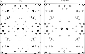
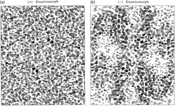
The multi-determination, ‘phase first’ approach for this DnaK structure gave MADLSQ statistics after mergers at 2.3 Å resolution of R (|°F T |) = 0.051, R (|°F A |) = 0.356, 〈Δφ〉 = 36.5° and 〈σ(Δφ)〉 = 17.2°, where Δφ = °ϕ T−°ϕ A. Before phase information given by the Δφ values can be used, the positions of anomalous scatterers, {r A}, are needed to derive the reference phases, °φ A. The accurately determined |°F A | coefficients from MADLSQ gave a Patterson map for the selenium positions (Fig. 4 a) that was readily interpreted by Patterson superposition program HASSP (Terwilliger & Berendzen, Reference Terwilliger and Berendzen1999) and validated by the corresponding |F calc| Patterson map from the deduced Se positions (Fig. 4 b). The substructure thus deduced is unavoidably ambiguous, however: if a set of positions {r A} satisfies the |°F A | coefficients, its enantiomoph {−r A} also does so equally well. This ambiguity must be resolved, for if {r A} gives phases °ϕ A, then {−r A} gives phases −°ϕ A; and only with the correct choice will the phase solutions, °ϕ T = Δφ + °ϕ A, be useful. A statistical basis for resolving the enantiomorph ambiguity has proved elusive, but electron-density maps derived from the alternatives are decisive when phase evaluations are accurate as they were here (〈σ(Δφ)〉 = 17.2°). When the hand is correct (Fig. 5 b), the density map shows clearcut molecular boundaries and structural features; whereas the map from the wrong hand (Fig. 5 a) is without recognizable features.
Patterson maps for Se positions of DnaK substrate-binding domain (SBD). (a) Map based on experimentally derived |°F A|2 coefficients. (b) Map based on the Se model derived from |F calc(6 Se)|2 coefficients. In each case, the Harker section at w = ½ is shown with density at 3.5 Å resolution.

Density distributions for DnaK SBD based on enantiomeric Se alternatives. (a) Map based on phases derived from the Se substructure as determined by Patterson superposition methods, the ( + ) enantiomorph. (b) Map based on phases derived from the alternative Se substructure having each z coordinate changed to −z, the (−) enantiomoph. Each distribution was produced at 2.3 Å resolution, and each image includes equivalent slabs of sections at +z and −z, respectively.

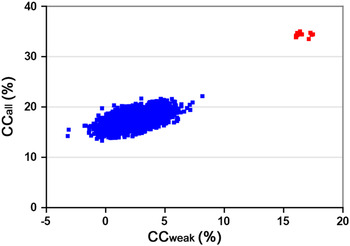
Our unified analysis of MAD data, whereby |°F A | coefficients are extracted as in the DnaK analysis (Fig. 4), can provide a rigorous solution of the substructure problem. Such rigor is not essential, however; even the Bijvoet differences at a single wavelength suffice in many cases, and this is crucial for SAD phasing. The problem of finding anomalous scatterer positions was first solved by Rossmann (Reference Rossmann1961), who showed that positions for the anomalous scatterers could be obtained from a Patterson map based on (|F(h)|−|F(−h)|)2 coefficients. This approximation can be appreciated from Eq. (6), which shows ΔF ±h to be directly proportional to |°F A | but reduced by sin(Δφ). Terwilliger (Reference Terwilliger1994) showed that |°F A | estimates can be improved by the use of prior expectations, going toward correction for the trigonometric factor. Nevertheless, the vast majority of MAD and SAD substructure determinations simply use the Rossmann approximation. An important development for substructure determination has come from the direct methods approach, first applied in the analysis of selenomethionyl S-adenosylhomocysteine hydrolase (Turner et al. Reference Turner, Yuan, Borchardt, Hershfield, Smith and Howell1998) where the Shake-and-Bake (SnB) algorithm as applied to Bijvoet differences (Smith et al. Reference Smith, Nagar, Rini, Hauptman and Blessing1998) found all 30 Se atoms. The SHELXD implementation (Schneider & Sheldrick, Reference Schneider and Sheldrick2002) of the SnB algorithm (Hauptman, Reference Hauptman1997) has been especially effective. In this approach, random starting structures are refined by iterations of tangent-formula refinement and real-space model adjustments against Bijvoet-difference estimates of |°F A |, using correlation-coefficient tests to find ‘solutions’ that stand out from the noise. Substructure determination from a native SAD application to intact DnaK–ATP (Liu et al. Reference Liu, Liu and Hendrickson2013) is shown in Fig. 6. Direct methods procedures were instrumental in extending the reach of MAD to large selenomethionyl proteins (Deacon & Ealick, Reference Deacon and Ealick1999).
Profile of correlation coefficients (CCs) from a substructure determination. The comparisons here are between observed Bijvoet differences from a TorT/TorS crystal and those calculated in SnB trials. The distribution of CCall and CCweak values is from 2000 SHELXD solution attempts. Successful solutions (14) are colored red and random solutions (1886) are colored blue. Reproduced from Fig. 2G of Liu et al. (Reference Liu, Dahmane, Zhang, Assur, Brasch, Shapiro, Mancia and Hendrickson2012) with permission from Acta Crystallographica D, © 2012 by the International Union of Crystallography.

Phase evaluation itself can proceed once the anomalous substructure is known. Two distinct approaches are taken. In one, the unified formalism of Eq. (4) or (3) more generally, is used. The structure of anomalous scatterers serves to specify the associated °ϕ A phases; and, subject to the enantiomorph ambiguity discussed above, an algebraic definition of the desired °ϕ T phase can be obtained. In practice, especially since data sets are often incomplete, a more comprehensive description of the phase information is given by a probabilistic treatment (Pähler et al. Reference Pähler, Smith and Hendrickson1990). Having determined the anomalous substructure, often from Bijvoet differences, |°F A| and °ϕ A can be calculated and |°F T|≈〈| λ i F(h)|2〉½ can be estimated; thereupon the joint probability distributions, P(|°F T|, °ϕ T), can be produced and integrated to yield the best Fourier coefficients.
Alternatively, MAD experiments can be analyzed as in situ MIR experiments (Phillips & Hodgson, Reference Phillips and Hodgson1980), based on differences from physics instead of from chemistry. In this approach, data from one of the wavelengths are chosen for the reference data set, and differences are taken relative to these data. The first structure to be analyzed in a MAD-as-MIR approach was that of histone H5 (Ramakrishnan et al. Reference Ramakrishnan, Finch, Graziano, Lee and Sweet1993), and this method of analysis quickly took hold (Ramakrishnan & Biou, Reference Ramakrishnan and Biou1997). Various computer programs are used in MAD-as-MIR analyses, including MLPHARE (Otwinowski, Reference Otwinowski, Wolf, Evans and Leslie1991), SOLVE (Terwilliger & Berendzen, Reference Terwilliger and Berendzen1999), SHARP (de la Fortelle & Bricogne, Reference de la Fortelle and Bricogne1997) and PHASES (Furey & Swaminathan, Reference Furey and Swaminathan1997). Although the unified and MAD-as-MIR approaches do often give similar solutions, they are distinguished, in principle, in that the structure factors at a particular wavelength, λF(h), correspond to a general density function (Hendrickson & Sheriff, Reference Hendrickson and Sheriff1987), which is complex due to anomalous scattering contributions, f Δ = f′ + i f″. The general density function may depart significantly from the true electron-density function, which is purely real as determined by the structure factors due to normal scattering factors, f°. While often just a nuance, the distinction is not ignorable when anomalous scattering is large fraction of the total (e.g. Rudenko et al. Reference Rudenko, Henry, Henderson, Ichtchenko, Brown, Goldstein and Deisenhofer2002; Weis et al. Reference Weis, Kahn, Fourme, Drickamer and Hendrickson1991).
6. Evolution of SAD
Compared to the course of development for MAD, SAD emerged slowly and then accelerated remarkably after a gestation nurtured by MAD. An appealing characteristic of MAD phasing is its prospect for unambiguously definitive phase evaluations. In practice, this appeal of MAD for giving decisive answers was realized right from the first applications, even when the anomalous scattering signals were relatively weak. SAD carries much the same potential as MAD for decisive phasing, but this comes with a trigonometric ambiguity intrinsic to the basic phasing relationship of Eq. (6). SAD is like SIR in this respect, where incorporation of the orthogonal information from anomalous scattering into SIRAS resolves the phase ambiguities. MAD is the obvious resolving counterpart for SAD, giving the complementary phase information of Eq. (8). When such orthogonality is not feasible or ineffective, as when measurements are remote from absorption resonances, the resolution of phase ambiguity becomes a critical issue.
SAD experiments are a subset of MAD experiments. Although wavelength changes are not involved, tuning to a resonance edge or to exceptionally low energy is often used for signal optimization. Thus, synchrotron radiation is important even if not essential for SAD. Nearly all aspects of data measurement and analysis described above for MAD also carry over to SAD. What differs most is the need to add information beyond anomalous scattering to resolve the phase ambiguity.
6.1 Crambin and phase ambiguity
Crambin was the first macromolecular structure to be determined de novo from the diffraction data of a single crystal and it was the first to be analyzed without incorporating exogenous heavy atoms (Hendrickson & Teeter, Reference Hendrickson and Teeter1981). Crambin is a very small protein (46 residues) and it diffracts exceptionally well (d min < 0.48 Å; Schmidt et al. Reference Schmidt, Teeter, Weckert and Lamzin2011); nevertheless, for its time it presented a substantial challenge. Sulfur SAD phasing was used to determine the structure, although the procedure was not identified then as SAD.
The diffraction data from a monoclinic crystal of crambin were measured at room temperature with CuKα radiation (sulfur f″ = 0.56e) by single-counter diffractometry, one reflection at a time. Bijvoet differences were measured to 1.5 Å spacings. Care was taken to reduce systematic errors by measuring data in blocks of 25 reflections at (φ, ψ, 2θ) followed by the corresponding Friedel mates at (φ, ψ, −2θ) and by applying a parameterized local scaling before differencing. Care was also taken to use counting times sufficient to assure adequate counting statistics. The error level for the data set, taking into account a term for instrumental instability, was rms (σ ΔF) = 1.6e as compared to rms (ΔF ±h ) = 2.3e, which was 2.1% of rms (|F|). Bijvoet-difference Patterson maps were used to solve for the sulfur positions, first at 3 Å resolution where disulfide-bonded atoms are not resolved and then at 1.5 Å resolution to deduce the six-atom sulfur structure. Only the subset of 38% of reflections with strongest Bijvoet differences, where sin(Δφ)≈1; so that |ΔF ±h | gives |°F A(h)| directly, were used to refine the sulfur substructure.
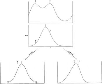
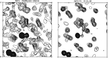
From the Bijvoet-difference relationship used for the crambin analysis, Eq. (6), the phase ambiguity of SAD is evident. Once the general enantiomorph ambiguity is resolved, there still exists for each acentric reflection the ambiguity that °ϕ T = °ϕ A±sin−1[2(f″A/f°A)/|°F A |]. In terms of phase probability (Hendrickson, Reference Hendrickson1979), this in general presents a bimodal probability distribution (Fig. 7) although the distribution may be unimodal if the alternative phases are close to one another. A figure-of-merit weighted map with centroid phases will give the least error (Blow & Crick, Reference Blow and Crick1959); such a map will still be inaccurate, however it can be improved greatly with appropriate resolution of the phase ambiguity. For the crambin analysis, partial-structure phase information coming from the sulfur atoms was used for ambiguity resolution in a scheme for making choices between alternatives when the discriminative probability is high and for using multiplicative phase combination otherwise (Hendrickson, Reference Hendrickson1971; Fig. 7 s). The sulfur partial structure here is relatively weak (〈|°F A |〉/〈|°F T |〉 = 2.9%), however, and the resulting density map (Fig. 8) was poor compared with those from later MAD experiments (Figs 3 and 5). This map did nevertheless prove to be interpretable into a well determined structure, thanks largely to the high resolution.
Scheme of options used for resolving phase ambiguity with crambin. (Above) Bimodal ‘SAD’ probability distribution based on the Bijvoet difference for a particular reflection (Hendrickson, Reference Hendrickson1979). (Middle) Partial structure probability distribution based on the sulfur substructure. (Below) Options of multiplicative phase combination of the top two profiles (‘COMBINE’) or choice of the symmetrized modal distribution (Hendrickson, Reference Hendrickson1971) corresponding to the ‘SAD’ alternative, φ 1, that has partial-structure probability significantly higher than for the lesser alternative, φ 2 (‘CHOOSE’).

Electron-density maps from the structure analysis of crambin. (Left) Experimental map with ‘SAD’ phases resolved by the partial-structure anomalous-choice procedure. (Right) Model-phased (2F obs – F calc) map from the final model refined at 1.5 Å resolution. The portion shown in these frames includes the disulfide-bonded sulfur atoms from Cys16–Cys26 at lower left, Sγ of Cys32 near the center and disulfide-bonded to Sγ of Cys4 (mostly out of the section), and the five-membered ring of Pro5 just above center. Reproduced from Fig. 2 of Hendrickson & Teeter (Reference Hendrickson and Teeter1981) with permission from Nature, © 1981 Macmillan Publishers Ltd.

The partial-structure resolved anomalous phasing method was used for a few other analyses (Conner et al. Reference Conner, Takano, Tanaka, Itakura and Dickerson1982; Sheriff et al. Reference Sheriff, Hendrickson and Smith1987; Smith et al. Reference Smith, Hendrickson and Addison1983), but such approaches were quickly overwhelmed by the growing successes of MAD phasing.
6.2 Ambiguity resolution from density modification
If only by comparison with the decisiveness of MAD, it became apparent that anomalous substructures alone are not generally adequate for effective resolution of phase ambiguity in single-wavelength anomalous phasing experiments. A striking example came with the application to a trimeric hemerythrin (Smith et al. Reference Smith, Hendrickson and Addison1983) where the di-iron sites of this metalloprotein were used in resolved anomalous phasing to obtain an initial map, which was inadequate for interpretation on its own but was improved dramatically by threefold molecular averaging and ‘solvent leveling’, as it was then described (Fig. 9). Similarly dramatic enhancements from symmetry averaging had been seen in the structure analysis of influenza virus hemagglutinin (Wilson et al. Reference Wilson, Skehel and Wiley1981). Non-crystallographic symmetry clearly provides a powerful means form ambiguity resolution, but it is not a general solution.
Electron-density maps from the structure analysis of trimeric hemerythrin. (Left) Experimental map with ‘SAD’ phases resolved by the iron partial structure. (Right) Experimental map after refinement by iterative threefold molecular averaging and solvent leveling.

A general and powerful solution came with the innovation of procedures for molecular envelope definition and solvent flattening (Wang, Reference Wang1985). As applied to anomalous scattering problems, this procedure was called the iterative single-wavelength anomalous scattering (ISAS) method, and as such its first application to an unknown was to a neurophysin–dipeptide complex using an iodinated derivative (Chen et al. Reference Chen, Rose, Breslow, Yang, Chang, Furey, Sax and Wang1991). A second application of this kind was made in the corrected analysis of Cd, Zn metallothionein (Robbins et al. Reference Robbins, McRee, Williamson, Collett, Xuong, Furey, Wang and Stout1991). A direct-methods approach to ambiguity resolution, called one-wavelength anomalous scattering (OAS), was also devised and tested (Fan & Gu, Reference Fan and Gu1985); and this procedure was used in an application to the copper protein rusticyanin (Harvey et al. Reference Harvey, Hao, Duke, Ingledew and Hasnain1998). Phases for rusticyanin from the OAS procedure were not sufficiently accurate to produce a readily interpretable map (Harvey et al. Reference Harvey, Hao, Duke, Ingledew and Hasnain1998); however, refinement with density modification as implemented by Cowtan & Main (Reference Cowtan and Main1993) did produce the structure. Direct methods by way of Sayre's equation had also been ineffective in the crambin study (Hendrickson & Teeter, Reference Hendrickson and Teeter1981).
Density modification continued to develop after Wang's introduction of solvent flattening (1985) with the incorporations of histogram matching (Zhang & Main, Reference Zhang and Main1990), the systematic inclusion of molecular averaging (Cowtan & Main, Reference Cowtan and Main1993), the innovation of solvent flipping (Abrahams & Leslie, Reference Abrahams and Leslie1996), the introduction of maximum-likelihood (Terwilliger, Reference Terwilliger2000), and with varied implementations as reviewed by Cowtan (Reference Cowtan2010). Another noteworthy addition to crystallographic practice with relevance to the interpretability of density maps was the introduction of automated chain tracing with the program ARP/wARP (Perraskis et al. Reference Perraskis, Morris and Lamzin1999) and successors such as RESOLVE (Terwilliger, Reference Terwilliger2003a, Reference Terwilligerb) and BUCCANEER (Cowtan, Reference Cowtan2006). With these advances in computational procedures, the trigonometric phase ambiguity of SAD could be resolved to extract the intrinsic phase definition of careful experiments.
6.3 SAD becoming the method of choice
As density-modification procedures were implemented and the resulting power for effective ambiguity resolution was recognized, new opportunities became apparent and additional single-wavelength anomalous analyses were performed (Biou et al. Reference Biou, Shu and Ramakrishnan1995; Turner et al. Reference Turner, Yuan, Borchardt, Hershfield, Smith and Howell1998). Then, using hen egg-white lysozyme as a test system, Dauter and co-workers showed that density-modification resolved phasing could be effective when based on atoms intrinsic to the structure (Dauter et al. Reference Dauter, Dauter, de La Fortelle, Bricogne and Sheldrick1999) or based on introduced bromide atoms (Dauter & Dauter, Reference Dauter and Dauter1999). The intrinsic-atom study (sulfur and chlorine) was performed at the wavelength of CuKα to emphasize that crambin-like analyses well away from absorption edges would now be straightforward, and this analysis used a combination of programs SHELXM (Sheldrick, Reference Sheldrick and Fortier1998), SHARP (de la Fortelle & Bricogne, Reference de la Fortelle and Bricogne1997) and SOLOMON (Abrahams & Leslie, Reference Abrahams and Leslie1996). The bromide ion studies were performed at or near K-edge resonance, and this analysis used a combination of SHELXM (Sheldrick, Reference Sheldrick and Fortier1998), DM (Cowtan, Reference Cowtan1994) and MLPHARE (Otwinowski, Reference Otwinowski, Wolf, Evans and Leslie1991). A key validation of the potential for sulfur SAD phasing came in the structure determination of obelin (Liu et al. Reference Liu, Vysotski, Chen, Rose, Lee and Wang2000), which was performed at a wavelength of 1.74 Å and used a combination of SOLVE (Terwilliger & Berendzen, Reference Terwilliger and Berendzen1999) and PHASES (Furey & Swaminathan, Reference Furey and Swaminathan1997) to find the sulfur sites and the ISAS solvent flattening (Wang, Reference Wang1985) for phase evaluation.
Even earlier, the PDB deposition for a green fluorescent protein (GFP) structure (Ormö et al. Reference Ormö, Cubitt, Kallio, Gross, Tsien and Remington1996) provided, to my knowledge, the first recorded use of the SAD acronym in citing ‘MIR/SAD’ as the method of determination to describe an analysis of selenomethionyl GFP. ‘SAD’ was also used in the Dauter papers on using sulfur and bromine as anomalous scatterers, but this was done off-handedly as if the term were already commonplace. It was used again in reporting the structure of psoriasin (Brodersen et al. Reference Brodersen, de La Fortelle, Vonrhein, Bricogne, Nyborg and Kjeldgaard2000) and in a re-evaluation of seven structural analyses of selenomethionyl proteins (Rice et al. Reference Rice, Earnest and Brunger2000). In the latter study, two structures were SAD-phasing rescues for MAD-phasing failures, spoiled by radiation damage; for the other five cases, the maps from density-modified SAD phases were nearly as good as those from MAD phases. With this background, Dauter et al. (Reference Dauter, Dauter and Dodson2002) then presented a defining mandate for SAD that reviewed the method and described fifteen tests and novel applications.
The growing successes of SAD spurred a renewed interest in home-source experiments (Nagem et al. Reference Nagem, Ambrosio, Rojas, Navarro, Golubev, Garratt and Polikarpov2005; Yang & Pflugrath, Reference Yang and Pflugrath2001), notably employing x-rays generated from a chromium anode to better exploit sulfur anomalous scattering (Kitago et al. Reference Kitago, Watanabe and Tanaka2005; Yang et al. Reference Yang, Pflugrath, Courville, Stence and Ferrara2003) or to take advantage of the anomalous scattering from iodine as its LI edge is approached (Evans & Bricogne, Reference Evans and Bricogne2003). Nevertheless, synchrotron radiation provides compelling advantages; fine tuning of x-ray energy makes it possible to optimize the strength of f″ at the Se K-edge and other resonance peaks, and access to lower x-ray energies permits the enhancement of anomalous signals from low-Z elements such as sulfur since f″ values increase as these K-edges are approached (Weiss et al. Reference Weiss, Sicker, Djinovic-Carugo and Hilgenfeld2001). The synchrotron advantage for selenium is responsible for most of the surge in selenomethionyl SAD structures documented below and the low-energy advantage is beginning to have an impact for sulfur SAD structures as multi-crystal experiments are developed.
6.4 Multi-crystal enhancement of signal-to-noise ratios
Although SAD has become the method of choice for de novo phase evaluation in crystallographic structure determination, it has remained relatively ineffective for challenges where diffraction is poor or signals are too weak. A recent analysis of SAD-phased structures in the Protein Data Bank (PDB) found only a small fraction to be at low resolution or to be based on native, low-Z elements (Liu et al. Reference Liu, Liu and Hendrickson2013). Among the 5286 identified SAD entries as of April 2012, only 32 structures were at low resolution (d min ⩾ 3.5 Å) and only 58 structures were based only on light atoms (Z ⩽ 20). Moreover, the only-light-atom (sulfur SAD) structures were at relatively high resolution: 74% at higher than 2 Å resolution; all at higher than 2.3 Å resolution. While the limited output of structures from low-resolution and only-light-atom SAD experiments might be due to a scarcity of such applications, it seemed more likely to have reflected complications from feeble anomalous signals embedded in noisy diffraction data.
We hypothesized that success with challenging SAD experiments could be improved by increasing the multiplicity of measurements; thereby, the enhancement in signal-to-noise over that from a single measurement is expected to be √M, where M is the multiplicity. Such improvements had been demonstrated for phosphorous SAD from a relatively large crystal of a DNA oligomer (Dauter & Adamiak, Reference Dauter and Adamiak2001); however, more typical macromolecular crystals cannot sustain multiple cycles of measurement without unacceptable radiation damage. Averaging from multiple crystals is an obvious solution; however, with cryoprotection, macromolecular crystallography had devolved into the search for one good crystal. Usually, one frozen crystal sufficed, and this was seen as preferable to multi-crystal averaging because crystal variation was expected due to stochastic lattice changes with flash freezing. For multi-crystal SAD experiments, it was thus important to assure that only crystals with statistically equivalent diffraction would be included. Clustering tests for such assurance were devised based on lattice dimensions, overall intensity patterns and anomalous diffraction profiles (Liu et al. Reference Liu, Dahmane, Zhang, Assur, Brasch, Shapiro, Mancia and Hendrickson2012). Figure 10 exemplifies such clustering.
Variations among crystals from a multi-crystal data set. (Left) Pairwise cluster analysis of unit cell variations. (Center) Pairwise cluster analysis of overall intensity variations. (Right) Relative anomalous correlation coefficient comparing Bijvoet differences from each crystal to those from the average of all together. Crystal 8 was eliminated as an outlier from the distribution, but the others were judged to be statistically equivalent and included for structure determination. Adapted from Fig. 1 of Liu et al. (Reference Liu, Dahmane, Zhang, Assur, Brasch, Shapiro, Mancia and Hendrickson2012) with permission from Science, © 2012 American Association for the Advancement of Science.

The idea of multi-crystal SAD phasing was tested first with selenomethionyl protein crystals at low resolution. We used the large extracellular domain of a histidine kinase receptor, which formed crystals that diffracted only to 3.5 Å Bragg spacings. With two copies in the asymmetric unit, this structure proved to be challenging in size as well as resolution; there proved to be 1456 ordered residues and 20 Se sites. Both the success in Se-substructure determination and the accuracy of resulting phase evaluations improved with the increasing multiplicity in diffraction from multiple crystals (Liu et al. Reference Liu, Zhang and Hendrickson2011). A particularly common instance of low-resolution selenomethionyl problems is found with crystals of detergent-solubilized membrane proteins, and the multi-crystal approach has proved instrumental in such low-resolution analyses for a dicarboxylate transporter (Mancusso et al. Reference Mancusso, Gregorio, Liu and Wang2012) and for a polyisoprenyl-phosphate glycosyltransferase (submitted for publication).
The challenge of only-light-atom native SAD analyses provided the second motivation for multi-crystal SAD experiments, and the methodology for such applications has also been described recently (Liu et al. Reference Liu, Dahmane, Zhang, Assur, Brasch, Shapiro, Mancia and Hendrickson2012, Reference Liu, Liu and Hendrickson2013). Five structures were determined in these tests, which used 5–13 crystals, included 4–52 anomalous scatterers, comprised 127–1200 ordered protein residues per asymmetric unit, and ranged in resolution from 2.3 to 2.8 Å.
Procedures were devised to make multi-crystal native SAD phasing robust and routine. First, it was in these applications that clustering procedures were devised to assure statistical equivalence of crystals admitted into averaging, employing tests on unit-cell deviations, diffraction dissimilarity and relative anomalous correlation coefficient (CC) (Fig. 10). As addressed above and advocated previously (Weiss et al. Reference Weiss, Sicker, Djinovic-Carugo and Hilgenfeld2001; Yang et al. Reference Yang, Pflugrath, Courville, Stence and Ferrara2003), enhanced f″ signals are expected at lower x-ray energy. We used the moderately low energy of 7 keV for our initial studies (Liu et al. Reference Liu, Liu and Hendrickson2013) since all of those crystals were relatively large; nevertheless, the use of a helium cone proved to be critical for the most challenging case (histidine kinase TorT/TorSS with 1148 residues and diffraction limited to 2.8 Å spacings). Standard data-reduction and scaling procedures were adopted, but with care to avoid including radiation-damaged frames. The enhancement in signal-to-noise was especially evident in the improvement of anomalous CC (from randomly split ΔF ±h data) for data after merging compared to those from each individual crystal (Fig. 11). Substructures were determined using the SnB procedure of SHELXD (Hauptman, Reference Hauptman1997; Schneider & Sheldrick, Reference Schneider and Sheldrick2002). Initial phases were evaluated by Phaser (Read & McCoy, Reference Read and McCoy2011), density modification was performed with DM (Cowtan & Zhang, Reference Cowtan and Zhang1999), and initial atomic models were built automatically with ARP/wARP (Langer et al. Reference Langer, Cohen, Lamzin and Perrakis2008).
Enhancement of anomalous signal-to-noise by multi-crystal averaging. Anomalous correlation coefficient (Anomalous CC) profiles as a function of Bragg spacings, comparing Bijvoet differences from five individual data sets with the data set compiled by averaging from all five. For individual DnaK-ATP data sets, the signal is essentially undetectable beyond 4.5 Å spacings and is at the 20% level down to ∼5 Å spacings; for the averaged data set, the signal is retained at the 20% level out to 3.5 Å spacings. Reproduced from Fig. 4 a of Liu et al. (Reference Liu, Liu and Hendrickson2013) with permission from Acta Crystallographica D, © 2013 by the International Union of Crystallography.

Four of the five structures analyzed in our initial multi-crystal native SAD experiments were novel. Two of these novel structures are now published (Brasch et al. Reference Brasch, Harrison, Ahlsen, Liu and Shapiro2011; Qi et al. Reference Qi, Sarbeng, Liu, Le, Xu, Xu, Yang, Wong, Vorvis, Hendrickson, Zhou and Liu2013) and papers are in preparation on the other two. Meanwhile, we and others have solved other structures by multi-crystal native SAD procedures. One on a flavivirus NS1 protein is recently published (Akey et al. Reference Akey, Brown, Dutta, Konwerski, Jose, Jurkiw, DelProposto, Ogata, Skiniotis, Kuhn and Smith2014) and another on a calcium-leak channel has been submitted for publication.
We anticipate that multi-crystal SAD procedures will have broad application to native macromolecules without recourse to heavy-atom incorporation (Liu et al. Reference Liu, Liu and Hendrickson2013). The initial set of applications included structures as large as 1200 amino-acid residues and at resolutions as limited as 2.8 Å. These are properties shared by 90% of current PDB holdings. Anticipated advances in synchrotron instrumentation and automation should facilitate making such experiments routine.
7. Applications and changing practice
At the outset, when MAD was instigated in the mid-1980s, such experiments were considered rather exotic and even heroic; moreover, the need for a new approach to de novo structure determination was then questionable in light of historic success with MIR and SIRAS. Ensuing applications showed convincingly that MAD was practical and that it could be the approach of choice for challenging structures. MAD was energized by technical innovations, notably cryopreservation and selenomethionyl proteins, and it flourished at beamlines designed expressly for MAD. MAD soon displaced MIR as the predominant de novo method; then, as density-modification procedures were perfected, SAD surpassed MAD. This section takes stock of current applications of anomalous diffraction in biological crystallography and changing practice in de novo structure determination.
7.1 Realms of application
The domain of MAD and SAD is nearly as broad as the periodic table itself. Each element has its distinctive resonant energies; and, as noted above in Section 5.2, all elements from Ca (Z = 20) to U (Z = 92) have K or LIII resonances in the energy range from 3.5 to 35 keV (3.5 to 0.35 Å in wavelength). Indeed, with specialized beamlines, the range can be extended down to 2.1 keV (5.8 Å) to include the K resonances from phosphorous and sulfur (Stuhrmann et al. Reference Stuhrmann, Bartels, Braunwarth, Doose, Dauvergne, Gabriel, Knöchel, Marmotti, Stuhrmann, Trame and Lehmann1997). Moreover, off-resonance f″ strength often suffices for SAD based on elements with resonances outside of accessible x-ray energies, which in practice may be restricted (e.g. 6 to 17 keV/2.1 to 0.7 Å). This opens significant opportunities for SAD with elements in the range 15 ⩽ Z ⩽ 24, where K-edge strength can be approached, and 40 ⩽ Z ⩽ 59 where L-edge strength can be approached. Success with sulfur SAD is a case in point. Indeed, even the anomalous scattering from oxygen can be used for structural characterization (Hope & de la Camp, Reference Hope and de la Camp1972).
With the sensitivity of anomalous diffraction and the wide-open options for useful elements, versatility abounds. All of the conventional heavy-atom derivatives, such as those with U, Hg, Au, Pt and Os are also ideal for MAD and/or SAD; intrinsic metal centers, including many first-series transition elements such as Fe, Cu and Zn as well as Mo and W from higher series, make almost all metalloproteins natural candidates; many lighter ions have ready and potent replacements, e.g. PO4 2+ by WO4 2+, SO4 2+ by SeO4 2+, and Ca2+ or Mg2+ by a lanthanide such as Yb3+; and there are several robust means for systematic incorporation. The most notable systematic approach is with selenomethionyl proteins (Doublié, Reference Doublié2007; Hendrickson et al. Reference Hendrickson, Horton and LeMaster1990); other possibilities include the synthesis of brominated or selenated nucleic acids (Sheng & Huang, Reference Sheng and Huang2010), the quick-soaked adsorption of solvent ions such as the halides Br− and I− (Dauter & Dauter, Reference Dauter and Dauter2001) or cations Cs+ or Gd3+ (Nagem et al. Reference Nagem, Dauter and Polikarpov2001), or the pressurized binding of noble gases Kr and Xe into hydrophobic cavities (Schiltz et al. Reference Schiltz, Fourme and Prangé2003).
Endowed with this rich armoury of phasing elements, biological crystallographers have expeditiously solved thousands of de novo macromolecular structures. These applications are from the complete range of biochemical systems, having in common only the need for de novo structure determination. Because of this bias toward novelty, the resulting MAD and SAD structures have often broken new ground for biological discoveries and structural precedents. Instances of application include metabolic enzymes [e.g. NO synthase (Raman et al. Reference Raman, Li, Martásek, Král, Masters and Poulos1998); HMG-CoA reductase (Istvan et al. Reference Istvan, Palnitkar, Buchanan and Deisenhofer2000)], DNA replication and repair systems [e.g. clamp-loader complex (Jeruzalmi et al. Reference Jeruzalmi, O'Donnell and Kuriyan2001); RecA:DNA recombination complex (Chen et al. Reference Chen, Yang and Pavletich2008); DNA polymerase η : DNA (Biertümpfel et al. Reference Biertümpfel, Zhao, Kondo, Ramón-Maiques, Gregory, Lee, Masutani, Lehmann, Hanaoka and Yang2010)], transcription factor complexes [e.g. TBP:TFIIA:DNA complex (Geiger et al. Reference Geiger, Hahn, Lee and Sigler1996); NFAT:Fos/Jun:DNA (Chen et al. Reference Chen, Glover, Hogan, Rao and Harrison1998); nuclear receptor PPARγ–RXRα:DNA complex (Chandra et al. Reference Chandra, Huang, Hamuro, Raghuram, Wang, Burris and Rastinejad2008)], RNA molecules [e.g. P4–P6 self-splicing intron (Cate et al. Reference Cate, Gooding, Podell, Zhou, Golden, Kundrot, Cech and Doudna1996), RNase P ribozyme:tRNA complex (Reiter et al. Reference Reiter, Osterman, Torres-Larios, Swinger, Pan and Mondragón2010)], signaling proteins [e.g. insulin receptor kinase (Hubbard et al. Reference Hubbard, Wei, Ellis and Hendrickson1994); EGF receptor ectodomain (Cho & Leahy, Reference Cho and Leahy2002)], cytoskeletal proteins [Arp 2/3 complex (Robinson et al. Reference Robinson, Turbedsky, Kaiser, Marchand, Higgs, Choe and Pollard2001); centriolar hub protein SAS-6 (Kitagawa et al. Reference Kitagawa, Vakonakis, Olieric, Hilbert, Keller, Olieric, Bortfeld, Erat, Flückiger, Gönczy and Steinmetz2011)], viral proteins [e.g. HIV integrase (Dyda et al. Reference Dyda, Hickman, Jenkins, Engelman, Craigie and Davies1994); papilloma virus E2 protein (Harris & Botchan, Reference Harris and Botchan1999)], vesicle transport proteins [SNARE complex (Sutton et al. Reference Sutton, Fasshauer, Jahn and Brunger1998); coatamer cage complex (Lee & Goldberg, Reference Lee and Goldberg2010)], molecular chaperones [e.g. trigger factor (Martinez-Hackert & Hendrickson, Reference Martinez-Hackert and Hendrickson2009; Hsp70 DnaK (Qi et al. Reference Qi, Sarbeng, Liu, Le, Xu, Xu, Yang, Wong, Vorvis, Hendrickson, Zhou and Liu2013)], membrane transporters [neurotransmitter transporter homolog LeuT (Yamashita et al. Reference Yamashita, Singh, Kawate, Jin and Gouaux2005); P-glycoprotein (Jin et al. Reference Jin, Oldham, Zhang and Chen2012)], and ion channels [stomatal anion channel (Chen et al. Reference Chen, Hu, Punta, Bruni, Hillerich, Kloss, Rost, Love, Siegelbaum and Hendrickson2010); voltage-gated sodium channel (Payandeh et al. Reference Payandeh, Scheuer, Zheng and Catterall2011)]. There are many more instances for these and other categories of application. Notable among them are high-significance challenges such as the first crystal structures of ribosomes [70S (Cate et al. Reference Cate, Yusupov, Yusupova, Earnest and Noller1999); 30S (Wimberly et al. Reference Wimberly, Brodersen, Clemons, Morgan-Warren, Carter, Vonrhein, Hartsch and Ramakrishnan2000)], transcriptional RNA polymerase (Cramer et al. Reference Cramer, Bushnell and Kornberg2001), and the G-protein-coupled receptor rhodopsin (Palczewski et al. Reference Palczewski, Kumasaka, Hori, Behnke, Motoshima, Fox, Le Trong, Teller, Okada, Stenkamp, Yamamoto and Miyano2000). From these precedents, other structures have followed by molecular replacement.
In addition to addressing the broad spectrum of structural biology associated with the projects of individual investigators, MAD and SAD also became instrumental in the development of the higher throughput approaches of structural genomics. The then newly realized efficacy of selenomethionyl MAD analysis of protein structure was a founding rationale for the structural genomics approach whereby structural representatives are sought for each sequence family in the protein universe (Shapiro & Lima, Reference Shapiro and Lima1998). De novo structure determination is essential here since the focus is on sequences without known structures, and selenomethionyl MAD crystallography seemed most expeditious. Indeed, selenomethionyl proteins became a mainstay for the protein production pipelines of all four large-scale centers of the NIH Protein Structure Initiative (PSI): JCSG (van den Bedem et al. Reference van den Bedem, Wolf, Xu and Deacon2011), MCSG (Kim et al. Reference Kim, Babnigg, Jedrzejczak, Eschenfeldt, Li, Maltseva, Hatzos-Skintges, Gu, Makowska-Grzyska, Wu, An, Chhor and Joachimiak2011), NESG (Xiao et al. Reference Xiao, Anderson, Aramini, Belote, Buchwald, Ciccosanti, Conover, Everett, Hamilton, Huang, Janjua, Jiang, Kornhaber, Lee, Locke, Ma, Maglaqui, Mao, Mitra, Patel, Rossi, Sahdev, Sharma, Shastry, Swapna, Tong, Wang, Wang, Zhao, Montelione and Acton2010) and NYSGXRC (Bonanno et al. Reference Bonanno, Almo, Bresnick, Chance, Fiser, Swaminathan, Jiang, Studier, Shapiro, Lima, Gaasterland, Sali, Bain, Feil, Gao, Lorimer, Ramos, Sauder, Wasserman, Emtage, D'Amico and Burley2005); however, as for the world more generally, SAD came to be preferred over MAD. Over the 10-year period of the PSI protein-universe effort, PSI-1 and PSI-2, 5097 atomic structures were deposited into the PDB, of which 4598 (90%) were crystal structures. These crystal structures included 1353 (29%) done by MAD and 2168 (47%) done by SAD.
In addition to the direct impact of anomalous diffraction in de novo structure determination, as exemplified by applications described above, ancillary benefits often accrue as well. First, the sites of anomalous scatterers can provide precise landmarks to assist in chain tracing at resolutions too low for clear residue identification for sequence alignment. This is particularly true for selenium sites marking the positions of methionine residues. There are many notable examples of such utility (e.g. Feng et al. Reference Feng, Campbell, Hsiung and MacKinnon2010; Jin et al. Reference Jin, Oldham, Zhang and Chen2012; Pomeranz Krummel et al. Reference Pomeranz Krummel, Oubridge, Leung, Li and Nagai2009; Sawaya et al. Reference Sawaya, Wojtowicz, Andre, Qian, Wu, Baker, Eisenberg and Zipursky2008; Wu et al. Reference Wu, Kwong and Hendrickson1997), including cases where methionine sites are introduced strategically by mutation (Leahy et al. Reference Leahy, Erickson, Aukhil, Joshi and Hendrickson1994). Second, information from anomalous diffraction measurements can be coupled usefully with molecular replacement. In favorable situations, the sites of anomalous scatterers can be used to specify the translational positioning, or even the orientation, of a known structure into the subject crystal [e.g. Bes et al. (Reference Bes, Parisini, Inda, Saraiva, Peleato and Sheldrick1999)]. More typically, when at least some part of a structure can be approximated by a replacement model, SAD phasing may be incorporated to remove phase bias and to define unmodeled portions of the structure. Indeed, in cases where the anomalous substructure is not readily solved, a molecular replacement solution may produce a readily interpretable Bijvoet-difference Fourier depiction of anomalous-scatterer positions. Combinations of molecular replacement with SAD, often called MR-SAD (Panjikar et al. Reference Panjikar, Parthasarathy, Lamzin, Weiss and Tucker2009; Read & McCoy, Reference Read and McCoy2011; Schuermann & Tanner, Reference Schuermann and Tanner2003), have become increasingly common; since 2009, 88 SAD structures (3%) included an MR component. Third, the element specificity of anomalous scattering provides a basis for unambiguous identification of ion sites. Classically, this has been done by taking measurements at diagnostic energies above and/or below that for an element in question. When the element in question has no resonance within the accessible energy range, ionic replacements have sometimes been used, such as Rb+ or Tl+ for K+ (Zhou & MacKinnon, Reference Zhou and MacKinnon2003) or Os(III) hexamine for Mg2+ hydrates (Kazantsev et al. Reference Kazantsev, Krivenko and Pace2009). Alternatively, we have shown that robust identifications can also be made through the refinement of f″ values against Bijvoet mates (Liu et al. Reference Liu, Liu and Hendrickson2013), especially for data measured at a low x-ray energy. Fourth, the definitive character of MAD phasing can lead to experimental phases with exceptional accuracy, and this can be useful in providing model-free pictures of solvation, motion and conformational heterogeneity (Burling et al. Reference Burling, Weis, Flaherty and Brunger1996). Accurate experimental phases from MAD phasing are particularly useful for analyses at low resolution (Bass et al. Reference Bass, Strop, Barclay and Rees2002; Rudenko et al. Reference Rudenko, Henry, Henderson, Ichtchenko, Brown, Goldstein and Deisenhofer2002).
7.2 Changing practice in de novo phase evaluation
The early history of macromolecular crystallography related almost entirely to de novo structure determination done by MIR. All structures presented at a watershed Cold Spring Harbor Meeting in 1971 (Watson, Reference Watson1972) either came directly from MIR (some reinforced with anomalous scattering, i.e. MIRAS or SIRAS) or were from difference-Fourier analyses of isomorphous ligand complexes. The first textbook on protein crystallography (Blundell & Johnson, Reference Blundell and Johnson1976) treated MIR extensively; however, while it gave excellent discussions of anomalous scattering and molecular replacement, there was almost nothing to report in practice. The emphasis for molecular replacement, as in the monograph by Rossmann (Reference Rossmann1972) by this very name, was on solving for phases from symmetry transformations. Molecular replacement as we know it now, for repositioning a known structure into the crystal of a relative, was mentioned only in citing a test at 5 Å resolution on seal myoglobin (Tollin, Reference Tollin1969). As recounted above, it was not until 1981 that anomalous scattering was shown to suffice on its own for biological structure determination (Hendrickson & Teeter, Reference Hendrickson and Teeter1981), introducing what we now call SAD. MAD followed in 1985 (Hendrickson, Reference Hendrickson1985; Kahn et al. Reference Kahn, Fourme, Bosshard, Chiadmi, Risler, Dideberg and Wery1985), but it took time for it to develop (Hendrickson, Reference Hendrickson1991).
Meanwhile, structure determination practices were changing rapidly. By the time that MAD was emerging, structures by de novo methods were already the minority fraction. We know this from statistics in our Macromolecular Structures (MS) series (Hendrickson & Wüthrich, Reference Hendrickson and Wüthrich2000). Starting in 1990 and on for a decade, through 1999, we compiled annual MS books of abstracts for structures meeting criteria of: (1) having an atomic model, (2) being experimentally derived, (3) being novel and (4) being macromolecular. MS 1991 (Hendrickson & Wüthrich, Reference Hendrickson and Wüthrich1991), reporting structures published in 1990, described 135 structures meeting the MS criteria as compared to 236 PDB depositions in total (57%); the remainder were from follow-up studies that had failed the novelty test, mainly as being ligand complexes or mutant variants of previously deposited structures. Already by 1990, the majority of MS-qualified x-ray structures (57/111) were determined by molecular replacement; among the 51 de novo structures, there were 78% by MIR (40), 12% by SIR (6), 8% by MAD (4) and one virus by ab initio molecular averaging. By 1999 (MS 2000), the number of MS-rated structures had risen to 929 but as a fraction of all PDB entries it had fallen to 36%. Among MS-rated x-ray structures, again a clear majority were determined by molecular replacement (58%) but the breakdown of de novo strutures was evolving to an increasing fraction done by MAD (Fig. 12).
Distribution of macromolecular structures of 1999 by determination method. (Left) Pie chart showing distribution among MS-rated (novel) and follow-up structures. (Right) Pie chart of MS-rated x-ray structures as divided among molecular replacement structures (MR) and de novo structures as determined by various methods.

To chronicle the evolution of MAD phasing applications, I undertook to produce a record of all published MAD structures meeting the MS criteria. An account of the progression through 1998 showed a slow start (1–4 entries per year during 1988–1993) followed by an exponential rise to 58 in 1998 (Hendrickson, Reference Hendrickson1999). This compilation was continued through 2001 (Fig. 13; Supplemental Table 1), at which point the growing flood of MAD structures became overwhelming (260 recorded for 2001); indeed, some might have been missed. Moreover, SAD structures were becoming numerous (21 for 2001); and a separate chronicle was developed for SAD, retrospectively including earlier off-resonance anomalous diffraction structures (Supplemental Table 2). In compiling structural results from the publications, rather than PDB entries, it was possible to glean experimental details on the x-ray source and phasing element. The breakdown on x-ray beamlines (Supplemental Table 3; Hendrickson, Reference Hendrickson1999, Reference Hendrickson2000) showed that by 2001 novel MAD and SAD structures had been determined at 44 different beamlines from 13 synchrotrons and also from CuKα sources. The breakdown on phasing elements shows coverage across the periodic table (Fig. 14; Supplemental Table 4; Hendrickson, Reference Hendrickson1999). These MAD and SAD experiments reflect all of the categories of application described above in section 7.1; however, not surprisingly, the distribution is far from uniform. Most notably, Se predominates (66% overall); however, the conventional heavy atoms (Hg, Pt, Au, Os), the transition metals of metalloproteins (Fe, Cu, Zn), and bromide ions and brominated nucleic acids (Br) also showed appreciable fractions at 13, 10 and 5%, respectively. Besides the phasing elements used in MAD and SAD structures through 2001 (Supplemental Tables 1 & 2), a few others that have been used subsequently (identified in Supplemental Table 5) are also included in the periodic chart (Fig. 14) but not in the bar graph.
Early growth in the production of anomalous diffraction structures. The number of structures based on MAD or SAD phase evaluation, published in a given calendar year, and meeting the criteria for inclusion in Macromolecular Structures (MS-rated; Hendrickson & Wüthrich, Reference Hendrickson and Wüthrich1991) is plotted year by year. Structures included here are identified in Supplemental Tables 1 & 2 and the statistics are summarized in Supplemental Tables 3 & 4. MAD structures are in solid black and the SAD structures are in open boxes. Updated from Fig. 1 of Hendrickson (Reference Hendrickson1999) with permission from the Journal of Synchrotron Radiation, © 1999 International Union of Crystallography.

Distribution of phasing elements used in anomalous diffraction analyses. The numbers of MS-rated (Hendrickson & Wüthrich, Reference Hendrickson and Wüthrich1991) MAD or SAD structures published through 2001 (Supplemental Tables 1 & 2) are plotted as a function of the atomic numbers of elements used in those phase evaluations (Supplemental Table 4). If an analysis used more than one anomalous element, all are included. A logarithmic scale (log2) is used because of the great disparity between numbers for Se and other elements (Se:Hg≈8; Se:Fe≈10). Atomic numbers having N = 1 are distinguished from those with N = 0 (log N indefinite) by small bars. The periodic table shown as an inset identifies elements that have been used for novel structure determinations by MAD or SAD phasing. Elements are colored green if any reported analysis included measurements made at resonance, whether by MAD or SAD; elements are colored yellow if only off-resonance measurements were used in the reported analyses. Elements first used in studies published after 2001 (Cl, Ca, Mn, Sr, Pd, Ba, Nd and Pr) are identified in Supplemental Table 5.

An alternative approach to the tracking of trends in structure determination became available when, starting in 1996, the PDB began to include details of the kind that were being abstracted into MS entries. To retrieve information of interest from PDB header records, we developed a parser for extracting and categorizing the depositor declarations on ‘method used to determine the structure.’ We sorted those entries from de novo determinations into MIR, SIR, MAD, SAD and ab initio categories, including variant descriptors such as MIRAS, SIRAS, SE-MET MAD PHASING, SAS or DIRECT METHODS, respectively, into these groupings. The progression of changing practice in de novo structure determination is illustrated in Fig. 15. Three things are notable. First, over this period of record, the total number of de novo structures grew dramatically from an annual average of ∼300 in the span from 1997 to 2000 to nearly 1400 annually ten years later in the span from 2007 to 2010. The drop to ∼1100 de novo structures per year in the last two full years can be ascribed to the ending of the high-throughput phase of PSI; whereas annual PSI output of SAD plus MAD structures averaged 597 during 2007–2009, this dropped to 521 in 2010 (transition year between PSI-2 and PSI:Biology) and then to 230 on average during PSI:Biology years 2011–2012. Second, promoting the growth in total de novo structures, there was a dramatic shift in market share from analyses by isomorphous replacement (MIR and SIR, reddish bars) to analyses by anomalous diffraction (MAD and SAD, greenish bars) analyses. At the start of the period, 80% of de novo structures were done by MIR or SIR; whereas a decade later, nearly 90% were done by MAD or SAD. Already by 2000, more structures were done by MAD than by MIR and SIR combined. Third, SAD now predominates altogether. SAD overtook MAD in 2006, and now nearly 70% of all de novo structures are SAD structures.
Changing practice in de novo structure determination. Depositor declarations for the method of structure determination were parsed from PDB entries beginning in 1997, the first full year for such recordings. Declarations judged to be synonymous were reduced to five de novo options; thus, for example, MIR includes MIRAS determinations, SIR includes SIRAS, and ab initio includes ‘direct methods’. Numbers were normalized into percentages of total de novo determinations in each year, and plotted in histograms identified by color coding. Multiple declarations (e.g. SIR and MAD) were counted for each method, but there were few such instances. The total number of de novo structures is plotted year by year as identified; 2013 is excluded because of incompleteness in releases. Results here are from the PDB holdings of 10 December 2013. Updated and elaborated from Fig. 3 of Hendrickson (Reference Hendrickson2013) with permission from Acta Crystallographica A, © 2013 International Union of Crystallography.

I estimate that, over all of biological crystallography through 2012, 77% of the x-ray crystal structures determined by de novo methods were done by MAD or SAD. For the period of 1960–1996 (from atomic-level myoglobin until PDB deposits came to include methods records), I estimate that 430 MS-rated structures were done by MIR and SIR. This number is deduced by starting from our estimate of 2346 total x-ray structures through 1996 (Hendrickson & Wüthrich, Reference Hendrickson and Wüthrich2000), assuming a de novo fraction (21.6%) as found for 1990 (MS 1991), subtracting the 67 MAD and 7 SAD structures recorded from publications (Supplemental Tables 1 & 2), and neglecting ab initio structures. For the period of 1997–2012, based on PDB records, the integrated totals for MAD and SAD (11 395 for 79.6%) are much larger than those for MIR and SIR (2604 for 18%). By summing over the two periods, I arrive at the 77% estimate for MAD and SAD overall. A small but steady residual fraction (∼3% overall) of de novo structures have come from ab initio methods. It should be noted that another small fraction of de novo determinations (<1%) have made use of multiple de novo methods (mainly MAD + MIR). Of course, nearly all current de novo structure determinations take advantage of density modification, and some also include molecular replacement information. That said, generally speaking, MAD and SAD are self-sufficient and reliably effective methods. Indeed, that effectiveness was clearly such as to motivate the community to adopt MAD and then SAD as methods of choice. Associated with this shift in behaviour, the increases from MAD and SAD after 2000 correlate with a concomitant growth in total de novo structure determinations (Fig. 15), which is consistent with efficiency of the anomalous diffraction approach.
7.3 Future prospects
Anomalous diffraction has moved from being ancillary to predominating for de novo structure determination, and this dominance seems likely to continue for some years. Indeed, it is difficult to imagine what might overtake SAD. An advance in ab initio methods could happen, but there is no evidence in the historical record (Fig. 15) for incipient ascendency; moreover, theoretical and practical limitations on size and resolution complicate broad applicability. Molecular replacement will doubtless continue to advance as more ‘knowns’ become available to serve as templates and improved methods permit the detection of ever smaller portions of unknown structures. Still, truly novel structures will demand de novo phase evaluation, and many of these structures are likely to present crystallographic challenges.
The frontier for MAD and SAD technology lies in efficaciously tackling small crystals of large, radiation-sensitive molecular systems that diffract no better than to moderate resolution. Progress with such challenges will likely need one or another improvement: sound analytical procedures to address extremes of both very weak and extraordinarily large signals, enhancement of anomalous signals such as from low-energy x-rays, possibly a new generation of phasing vehicles, enhancement of signal-to-noise ratios as from multiple crystals, improved computational procedures for handling data from multiple crystals, appropriate instrumentation for advanced x-ray sources and the presentation of small crystals, and appropriate applications to test the limits. Many applications will benefit from a coordinated implementation of multiple methodological improvements.
One challenging area where advanced methods might contribute concerns structure determination at low resolution, where atomic models are ill-specified. Solvent flattening approaches lose effectiveness at lower resolution, which makes accurate ambiguity resolution for low-resolution SAD structures problematic (although molecular averaging remains highly effective). On the other hand, properly performed MAD experiments can yield highly accurate phases (Burling et al. Reference Burling, Weis, Flaherty and Brunger1996) whenever the anomalous sites can be determined accurately. Situations are becoming commonplace where even best crystals diffract poorly (dmin ∼4 Å); examples include membrane proteins (Bass et al. Reference Bass, Strop, Barclay and Rees2002; Nyblom et al. Reference Nyblom, Poulsen, Gourdon, Reinhard, Andersson, Lindahl, Fedosova and Nissen2013), receptors (Rudenko et al. Reference Rudenko, Henry, Henderson, Ichtchenko, Brown, Goldstein and Deisenhofer2002), flexible multi-domain proteins (DeLaBarre & Brünger, Reference DeLaBarre and Brünger2003; Leonard et al. Reference Leonard, Różycki, Saidi, Hummer and Hurley2011) and multi-component complexes (Ataide et al. Reference Ataide, Schmitz, Shen, Ke, Shan, Doudna and Ban2011). Accurate structures at much lower resolution (∼6 Å) have proved to be highly informative, as was true for the globins (Kendrew et al. Reference Kendrew, Bodo, Dintzis, Parrish, Wyckoff and Phillips1958; Perutz et al. Reference Perutz, Rossmann, Cullis, Muirhead, Will and North1960) and hemerythrins (Hendrickson et al. Reference Hendrickson, Klippenstein and Ward1975; Smith et al. Reference Smith, Hendrickson and Addison1983; Ward et al. Reference Ward, Hendrickson and Klippenstein1975), and similar studies are likely to become important once again where intrinsic resolution is very limited.
Many low-resolution structures are from rather large systems, which in turn require strong anomalous scatterers for accurate phasing. An effective approach to strong anomalous signals has come through heavy-metal cluster compounds (Knäblein et al. Reference Knäblein, Neuefeind, Schneider, Bergner, Messerschmidt, Löwe, Steipe and Huber1997; Thygesen et al. Reference Thygesen, Weinstein, Franceschi and Yonath1996), which scatter as super-atoms when viewed at low-enough resolution (dmin > 4 Å). This can be a great boon to structure determination; e.g. we estimate that the complex of a Au102–gold cluster compound (Jadzinsky et al. Reference Jadzinsky, Calero, Ackerson, Bushnell and Kornberg2007) attached 4:1 to a 2.3 MDa tetramer of 5000-residue protein chains will produce Bijvoet-diffraction ratios (Eq. 9) of 110%. Signals of such strength will overpower many conventional phasing programs; indeed, complications were already noted from a tungsten-cluster complex with the LDL receptor (Rudenko et al. Reference Rudenko, Henry, Vonrhein, Bricogne and Deisenhofer2003). On the other hand, the exact MAD treatment (Eqs. 4–7) can handle such colossal MAD signals readily, as was demonstrated for the very large (∼27%) Ho LIII signals from the mannose-binding protein (Weis et al. Reference Weis, Kahn, Fourme, Drickamer and Hendrickson1991). Colossal cluster compounds can also be used at resolutions beyond the super-atom level; however, the cluster must then be resolved into its constituent atoms, and procedures have been described for doing so (Dahms et al. Reference Dahms, Kuester, Streb, Roth, Sträter and Than2013). Moreover, the low-resolution phases can be used in Bijvoet-difference analyses to find the potential sites of anomalous scattering in a very large structure, as for selenomethionyl proteins, halide soaks or some heavy-atom derivatives.
Heavy-atom cluster compounds are important as new phasing vehicles, as noted above, but other directions are in progress as well. Selenated compounds alternative to the predominating selenomethionine have also been introduced by biological synthesis into proteins, using selenatryptophan analogs of tryptophan (Bae et al. Reference Bae, Alefelder, Kaiser, Friedrich, Moroder, Huber and Budisa2001; Boles et al. Reference Boles, Henderson, Hatch and Silks2002) or selenocysteine to generate cystine-like diselenides (Strub et al. Reference Strub, Hoh, Sanchez, Strub, Böck, Aumelas and Dumas2003), and by chemical synthesis into nucleic acids (Sheng & Huang, Reference Sheng and Huang2010). Chelating frameworks for incorporating lanthanide ions (Girard et al. Reference Girard, Stelter, Vicat and Kahn2003; Purdy et al. Reference Purdy, Ge, Chen, Selvin and Wiener2002) provide potentially effective means for introducing these potent anomalous centers. Uranyl compounds can provide spectacular anomalous signals (Fig. 1 b; Liu et al. Reference Liu, Ogata and Hendrickson2001) and chelated delivery for such phasing vehicles might also be made possible. No doubt, other possibilities will emerge.
Another challenging category of application concerns native structures that are composed only from light atoms. Here the multi-crystal native SAD approach described above in Section 6.4 becomes important. The anomalous signals from the intrinsic sulfur and phosphorous atoms in biological macromolecules can be enhanced remarkably by using low-energy x-rays (Liu et al. Reference Liu, Liu and Hendrickson2013). This enhancement comes about as the K (1 s) resonances for S and P atoms at 2.472 keV (5.016 Å) and 2.1455 keV (5.779 Å), respectively, are approached. Thus, f″ signals increase with lower energy; however, so too does x-ray absorption and background scattering. Indeed, x-ray penetration depth decreases with energy such that the transmitted signals actually diminish for larger crystals (Fig. 16). By Bragg's law, scattering angles within diffraction patterns also increase. These factors cause complications, but ones that can be addressed by appropriate instrumentation and experimental design (Liu et al. Reference Liu, Liu and Hendrickson2013). Notably, the use of small crystals becomes imperative below 4 keV. An additional complication at lower energy comes from the contaminating anomalous noise from other organic elements (C, N and O), which is negligible at higher energy but increases at lower energy. Taking as an example the structure of the TehA homolog of anion channel SLAC1 (Chen et al. Reference Chen, Hu, Punta, Bruni, Hillerich, Kloss, Rost, Love, Siegelbaum and Hendrickson2010; PDB: 3M71), for which the ordered protein and water has the composition C1701 N350 O401 S9, we find that the intrinsic signal-to-noise ratio [rms(f″S)/rms(f″C,N,O)] drops from 1.98 at 7 keV to 1.49 at 3 keV. Such CNO noise should not become a problem, however, unless the sulfur/phosphorous content is low.
Dependence of transmitted anomalous signals on x-ray energy. To understand the effects of x-ray absorption on the anomalous signal to be expected from sulfur (f′ in electrons) in crystals of varying size, the x-ray transmission through various thicknesses of water was calculated as a function of x-ray energy. Water is used as having x-ray absorptivity similar to that of a protein crystal. Transmitted signals are plotted for various thicknesses; symbols identify the Se K-edge energy and selected relevant low-energy values. Reproduced from Fig. 2 of Liu et al. (Reference Liu, Liu and Hendrickson2013) with permission from Acta Crystallographica D, © 2013 by the International Union of Crystallography.

As discussed in Section 5.4 above, there are many existing computational options for analyzing MAD and SAD data. We can also expect continuing developments of direct and indirect relevance, notably from the PHENIX and CCP4 consortia. Surely there is room for improvements, for example in phase evaluation from very large anomalous signals and in the treatment of probability. The more open questions, however, concern procedures for the optimal assembly of complete data sets from the partial observations recorded from many crystals or multiple regions within crystals. One active area of study in this regard concerns the problem of crystal clustering and outlier identification, with new contributions appearing shortly after we reported our first results (Foadi et al. Reference Foadi, Aller, Alguel, Cameron, Axford, Owen, Armour, Waterman, Iwata and Evans2013; Giordano et al. Reference Giordano, Leal, Bourenkov, McSweeney and Popov2012; Liu et al. Reference Liu, Zhang and Hendrickson2011, Reference Liu, Dahmane, Zhang, Assur, Brasch, Shapiro, Mancia and Hendrickson2012) and programs to treat the single-shot data from serial femtosecond crystallography (White et al. Reference White, Barty, Stellato, Holton, Kirian, Zatsepin and Chapman2013). Another area of importance relates to the control and adjustment for systematic errors, for example by preserving the identity of inverse-beam pairings for local scaling (Hendrickson & Teeter, Reference Hendrickson and Teeter1981; Matthews & Czerwinski, Reference Matthews and Czerwinski1975) prior to globally collective scaling. Perhaps most importantly, there is an opportunity to improve resolution and data quality through improved monitoring and selection based on understanding of mechanisms of radiation damage (Hendrickson, Reference Hendrickson1976; Warkentin & Thorne, Reference Warkentin and Thorne2010).
On the instrumentation side, exciting developments are in store from new x-ray sources as well as at beamlines discussed above in Section 5.3. Most recently, entirely new approaches to biological structure analysis are emerging from serial femtosecond crystallography (Chapman et al. Reference Chapman, Fromme, Barty, White, Kirian, Aquila, Hunter, Schulz, DePonte, Weierstall, Doak, Maia, Martin, Schlichting, Lomb, Coppola, Shoeman, Epp, Hartmann, Rolles, Rudenko, Foucar, Kimmel, Weidenspointner, Holl, Liang, Barthelmess, Caleman, Boutet, Bogan, Krzywinski, Bostedt, Bajt, Gumprecht, Rudek, Erk, Schmidt, Hömke, Reich, Pietschner, Strüder, Hauser, Gorke, Ullrich, Herrmann, Schaller, Schopper, Soltau, Kühnel, Messerschmidt, Bozek, Hau-Riege, Frank, Hampton, Sierra, Starodub, Williams, Hajdu, Timneanu, Seibert, Andreasson, Rocker, Jönsson, Svenda, Stern, Nass, Andritschke, Schröter, Krasniqi, Bott, Schmidt, Wang, Grotjohann, Holton, Barends, Neutze, Marchesini, Fromme, Schorb, Rupp, Adolph, Gorkhover, Andersson, Hirsemann, Potdevin, Graafsma, Nilsson and Spence2011) at x-ray free electron lasers (FELs). This was first put into practice at Stanford's Linac Coherent Light Source (LCLS) and other sources are being developed worldwide. Radiation damage can be eliminated by using single-shot, diffraction-before-destruction procedures with nanocrystals, but challenges are faced in achieving the kind of accuracy required to measure anomalous diffraction signals. Nevertheless, results are beginning to emerge; tests with lysozyme show that SAD phasing of FEL data should become feasible (Barends et al. Reference Barends, Foucar, Botha, Doak, Shoeman, Nass, Koglin, Williams, Boutet, Messerschmidt and Schlichting2013, Reference Barends, Foucar, Shoeman, Bari, Epp, Hartmann, Hauser, Huth, Kieser, Lomb, Motomura, Nagaya, Schmidt, Strecker, Anielski, Boll, Erk, Fukuzawa, Hartmann, Hatsui, Holl, Inubushi, Ishikawa, Kassemeyer, Kaiser, Koeck, Kunishima, Kurka, Rolles, Rudek, Rudenko, Sato, Schroeter, Soltau, Strueder, Tanaka, Togashi, Tono, Ullrich, Yase, Wada, Yao, Yabashi, Ueda and Schlichting2014). In addition, MAD-like methods are being tested based on FEL-induced stripping of electrons from heavy atoms (Son et al. Reference Son, Chapman and Santra2011). New synchrotron sources are also under development. Most imminent are the National Synchrotron Light Source – II (NSLS-II) at Brookhaven, which is diffraction limited in the vertical, and MAX IV in Lund, which employs a novel multibend-achromat accelerator lattice to produce diffraction-limited emission horizontally as well as vertically. Upgrade implementations of such ultimate-storage-ring lattices are in planning for several existing machines.
The new synchrotron sources can readily produce very bright, low-divergence, micron-sized x-ray beams to match emerging needs generally. These qualities are especially important for the challenges of anomalous diffraction. For the optimization of MAD or SAD at resonance (Fig. 1), having high-energy resolution is critical. As shown in Fig. 17, poor energy resolution can spoil intrinsically sharp white-line features, such as at the K-edge resonance of selenomethionyl proteins. Signal strength is then reduced accordingly. We are developing microdiffraction beamline NYX at NSLS-II with a novel monochromator design that preserves intrinsic resonant signals. For the optimization of native SAD analyses, low-energy experiments are needed (see Section 6.4); here, when at the preferred lower reaches of energy, microcrystals and thereby microbeams are essential for optimization (Fig. 16). A new long-wavelength (low-energy) beamline (I23) is being built at Diamond, and a low-energy anomalous x-ray diffraction beamline (LAX) is approved for building at NSLS-II. For synchrotron beamlines as for FEL instruments, the appropriate delivery of small crystals into microbeams is a critical focus of instrument development. Detectors are another.
Dependence of apparent resonance strength on energy resolution. (Left) Anomalous scattering spectra measured from an E. coli selenomethionyl thioredoxin crystal at SSRL beamline 1–5, without any focusing elements (Hendrickson et al. Reference Hendrickson, Horton and LeMaster1990). (Center) Spectra measured from CHO-produced selenomethionyl human chorionic gonadotropin at NSLS beamline X4A, with focusing (Wu et al. Reference Wu, Lustbader, Liu, Canfield and Hendrickson1994). (Right) Spectra measured from selenobiotinyl streptavidin at horizontally focused PF beamline 14A, and analyzed subsequently relative to a comparable sample measured as above at SSRL 1–5 (Fanchon & Hendrickson, Reference Fanchon and Hendrickson1990). In each case, x-ray absorption spectra were measured from the selenoproteins by fluorescence, and then transformed into theoretical anomalous scattering for atomic selenium to yield experimental edge data on an absolute scale. The monochromator was of Si111 in all cases, and exactly the same analytical procedures and program were used in all cases (Hendrickson et al. Reference Hendrickson, Smith, Phizackerley and Merritt1988). Signal reductions are due to compromised energy resolution from beam divergences.

8. Supplementary material
Supplemental tables 1–5 can be found at http://dx.doi.org/10.1017/S0033583514000018.
9. Acknowledgements
I thank the many associates whose work over the past decades has contributed to our developments of MAD and SAD phase evaluation; most notably, I thank Janet Smith (our initial MAD phasing tests on lamprey hemoglobin), Arno Pähler (our first MAD application to an unknown, streptavidin), Craig Ogata (X4A synchrotron beamline) and Qun Liu (native SAD analyses). I also thank Arno Pähler for developing the PDB parser for analyzing the progress of de novo structure determinations, Jie Qin for help with figures, and Maggie Gabanyi and Helen Berman for PDB statistics on PSI structures. Finally, I am grateful to Qun Liu for his critical review and helpful comments. This work was supported in part by NIH grants GM034102 and GM095315, by NSF instrumentation grant DBI-0960034 (NYX beamline) and by the Howard Hughes Medical Institute.